User Manual
Page 13
... a Processor 3 Installing DDR4 memory 5 Connecting the Front Panel Header 6 Installing the Motherboard 7 Connecting the Power Connectors 8 Installing SATA Drives 9 Installing a Graphics Card 10 Connecting Peripheral Devices 11 Power On...12 Specifications...16 JCORSAIR1 Connector Specification 23 Package contents 23 Block Diagram ...24 Rear I/O Panel ...25 LAN Port LED Status Table 25 Audio Ports Configuration 25 Realtek Audio Console 26 Installing Antennas 28 Overview of Components 29 Processor Socket 31 DIMM Slots...32 PCI_E1~5: PCIe Expansion Slots 33 M2_1~3: M.2 Slots (Key...
... a Processor 3 Installing DDR4 memory 5 Connecting the Front Panel Header 6 Installing the Motherboard 7 Connecting the Power Connectors 8 Installing SATA Drives 9 Installing a Graphics Card 10 Connecting Peripheral Devices 11 Power On...12 Specifications...16 JCORSAIR1 Connector Specification 23 Package contents 23 Block Diagram ...24 Rear I/O Panel ...25 LAN Port LED Status Table 25 Audio Ports Configuration 25 Realtek Audio Console 26 Installing Antennas 28 Overview of Components 29 Processor Socket 31 DIMM Slots...32 PCI_E1~5: PCIe Expansion Slots 33 M2_1~3: M.2 Slots (Key...
User Manual
Page 14
... BIOS) Jumper 46 POWER1, RESET1: Power Button, Reset Button 46 JRGB1: RGB LED connector 47 JRAINBOW1~2: Addressable RGB LED connectors 48 JCORSAIR1: CORSAIR Connector 49 Onboard LEDs ...50 EZ Debug LED...50 JPWRLED1: LED power input 50 Debug Code LED 50 Hexadecimal Character Table 51 Boot Phases...51 Debug Code LED Table 51 ACPI States Codes 55 Installing OS, Drivers & Utilities 56 Installing Windows® 10 56 Installing Drivers 56 Installing Utilities 56 BIOS Setup ...57 Entering BIOS Setup 57 Resetting BIOS...58 Updating BIOS...58 EZ Mode ...60 Advanced Mode ...62 SETTINGS...
... BIOS) Jumper 46 POWER1, RESET1: Power Button, Reset Button 46 JRGB1: RGB LED connector 47 JRAINBOW1~2: Addressable RGB LED connectors 48 JCORSAIR1: CORSAIR Connector 49 Onboard LEDs ...50 EZ Debug LED...50 JPWRLED1: LED power input 50 Debug Code LED 50 Hexadecimal Character Table 51 Boot Phases...51 Debug Code LED Table 51 ACPI States Codes 55 Installing OS, Drivers & Utilities 56 Installing Windows® 10 56 Installing Drivers 56 Installing Utilities 56 BIOS Setup ...57 Entering BIOS Setup 57 Resetting BIOS...58 Updating BIOS...58 EZ Mode ...60 Advanced Mode ...62 SETTINGS...

User Manual
Page 16
... unavailable when installing the PCIe card in PCI_E4 slot. ***The speeds may vary for 2nd and 3rd Gen AMD Ryzen™ processors. ** The PCIe x1 slots can not be used simultaneously. Specifications CPU Chipset Memory Expansion Slots Multi-GPU LAN Supports 2nd and 3rd Gen AMD Ryzen™ / Ryzen™ with Radeon™ Vega Graphics and 2nd Gen AMD Ryzen™ with Radeon™ Graphics Desktop Processors for Socket AM4 AMD® X570 Chipset y 4x DDR4 memory slots, support up...
... unavailable when installing the PCIe card in PCI_E4 slot. ***The speeds may vary for 2nd and 3rd Gen AMD Ryzen™ processors. ** The PCIe x1 slots can not be used simultaneously. Specifications CPU Chipset Memory Expansion Slots Multi-GPU LAN Supports 2nd and 3rd Gen AMD Ryzen™ / Ryzen™ with Radeon™ Vega Graphics and 2nd Gen AMD Ryzen™ with Radeon™ Graphics Desktop Processors for Socket AM4 AMD® X570 Chipset y 4x DDR4 memory slots, support up...

User Manual
Page 48
... voltages, and connecting the 5V LED strip to the JRGB connector will result in damage to the LED strip. y Please use MSI's software to control the extended LED strip. 48 Overview of LED strips. In the case of 20% brightness, the connector supports up to 75 LEDs WS2812B Individually Addressable RGB LED strips (5V/Data/Ground) with the maximum power rating of 3A (5V). y Always turn off the power supply...
... voltages, and connecting the 5V LED strip to the JRGB connector will result in damage to the LED strip. y Please use MSI's software to control the extended LED strip. 48 Overview of LED strips. In the case of 20% brightness, the connector supports up to 75 LEDs WS2812B Individually Addressable RGB LED strips (5V/Data/Ground) with the maximum power rating of 3A (5V). y Always turn off the power supply...

User Manual
Page 52
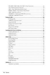
... specific) 78 ACPI module initialization 79 CSM initialization 7A - 7F Reserved for future AMI DXE codes 90 Boot Device Selection (BDS) phase is started 91 Driver connecting is started 92 PCI Bus initialization is started 52 Onboard LEDs Programming memory timing information 2E Memory initialization. Cache initialization 34 CPU post-memory initialization. Configuring memory 2F Memory initialization (other) 31 Memory Installed 32 CPU post-memory initialization is started 33 CPU post-memory initialization. Boot Strap Processor (BSP) selection 36 CPU post-memory initialization. Memory...
... specific) 78 ACPI module initialization 79 CSM initialization 7A - 7F Reserved for future AMI DXE codes 90 Boot Device Selection (BDS) phase is started 91 Driver connecting is started 92 PCI Bus initialization is started 52 Onboard LEDs Programming memory timing information 2E Memory initialization. Cache initialization 34 CPU post-memory initialization. Configuring memory 2F Memory initialization (other) 31 Memory Installed 32 CPU post-memory initialization is started 33 CPU post-memory initialization. Boot Strap Processor (BSP) selection 36 CPU post-memory initialization. Memory...
User Manual
Page 53
... Enable A8 Setup Verifying Password A9 Start of Setup AB Setup Input Wait AD Ready To Boot event AE Legacy Boot event AF Exit Boot Services event B0 Runtime Set Virtual Address MAP Begin B1 Runtime Set Virtual Address MAP End B2 Legacy Option ROM Initialization B3 System Reset B4 USB hot plug B5 PCI bus hot plug B6 Clean-up of NVRAM B7 Configuration Reset (reset of NVRAM settings) B8 - 93 PCI Bus Hot Plug Controller Initialization 94 PCI Bus Enumeration 32 95 PCI Bus...
... Enable A8 Setup Verifying Password A9 Start of Setup AB Setup Input Wait AD Ready To Boot event AE Legacy Boot event AF Exit Boot Services event B0 Runtime Set Virtual Address MAP Begin B1 Runtime Set Virtual Address MAP End B2 Legacy Option ROM Initialization B3 System Reset B4 USB hot plug B5 PCI bus hot plug B6 Clean-up of NVRAM B7 Configuration Reset (reset of NVRAM settings) B8 - 93 PCI Bus Hot Plug Controller Initialization 94 PCI Bus Enumeration 32 95 PCI Bus...

User Manual
Page 56
... the Drivers/Software tab. 5. Click the Select to open the installer. Installing OS, Drivers & Utilities Please download and update the latest utilities and drivers at www.msi.com Installing Windows® 10 1. Press the Restart button on the screen to get into your optical drive. 3. Press any key when screen shows Press any key to finish. 8. Select the utilities you must complete drivers installation. 1. Restart your computer. Press F11 key during the computer POST (Power...
... the Drivers/Software tab. 5. Click the Select to open the installer. Installing OS, Drivers & Utilities Please download and update the latest utilities and drivers at www.msi.com Installing Windows® 10 1. Press the Restart button on the screen to get into your optical drive. 3. Press any key when screen shows Press any key to finish. 8. Select the utilities you must complete drivers installation. 1. Restart your computer. Press F11 key during the computer POST (Power...
User Manual
Page 58
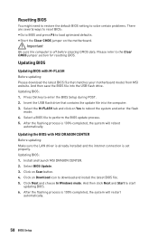
... Clear CMOS jumper section for resetting BIOS. Click Next and choose In Windows mode. And then click Next and Start to perform the BIOS update process. 5. yyShort the Clear CMOS jumper on Scan button. 4. Install and launch MSI DRAGON CENTER. 2. Click on the motherboard. Insert the USB flash drive that matches your motherboard model from MSI website. Select the M-FLASH tab and click on Download icon to download and install the latest BIOS file. 5. Click on Yes to load optimized defaults...
... Clear CMOS jumper section for resetting BIOS. Click Next and choose In Windows mode. And then click Next and Start to perform the BIOS update process. 5. yyShort the Clear CMOS jumper on Scan button. 4. Install and launch MSI DRAGON CENTER. 2. Click on the motherboard. Insert the USB flash drive that matches your motherboard model from MSI website. Select the M-FLASH tab and click on Download icon to download and install the latest BIOS file. 5. Click on Yes to load optimized defaults...
User Manual
Page 60
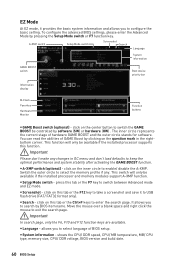
... basic setting. Switch the outer circle to select the memory profile if any changes in the rightbottom corner. yySearch - shows the CPU/ DDR speed, CPU/ MB temperature, MB/ CPU type, memory size, CPU/ DDR voltage, BIOS version and build date. 60 BIOS Setup A-XMP switch Setup Mode switch Screenshot Search Language System information GAME BOOST switch Boot device priority bar Information display M-Flash Favorites Hardware Monitor Function buttons yyGAME Boost switch (optional) - click on the question mark in OC menu and don't load defaults...
... basic setting. Switch the outer circle to select the memory profile if any changes in the rightbottom corner. yySearch - shows the CPU/ DDR speed, CPU/ MB temperature, MB/ CPU type, memory size, CPU/ DDR voltage, BIOS version and build date. 60 BIOS Setup A-XMP switch Setup Mode switch Screenshot Search Language System information GAME BOOST switch Boot device priority bar Information display M-Flash Favorites Hardware Monitor Function buttons yyGAME Boost switch (optional) - click on the question mark in OC menu and don't load defaults...

User Manual
Page 61
... disable the LAN Option ROM, ErP Ready, AHCI/ RAID, Indication LED Control, BIOS UEFI/CSM Mode and RGB Light Control by percentage. allows you to change the boot priority. you can move the device icons to select a BIOS menu (e.g. click on the CPU, Memory, Storage, Fan Info and Help buttons on favorite page (Favorite 1~5) 2. yyM-Flash - SETTINGS, OC...,etc) as the BIOS home page. ƒƒFavorite1~5 - allows you to add the frequently-used BIOS setting items. ƒƒDefault...
... disable the LAN Option ROM, ErP Ready, AHCI/ RAID, Indication LED Control, BIOS UEFI/CSM Mode and RGB Light Control by percentage. allows you to change the boot priority. you can move the device icons to select a BIOS menu (e.g. click on the CPU, Memory, Storage, Fan Info and Help buttons on favorite page (Favorite 1~5) 2. yyM-Flash - SETTINGS, OC...,etc) as the BIOS home page. ƒƒFavorite1~5 - allows you to add the frequently-used BIOS setting items. ƒƒDefault...

User Manual
Page 64
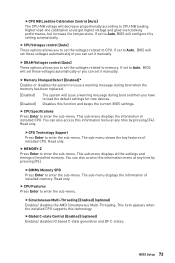
... Enabled. [Enabled] Enables UEFI network stack. [Disabled] Disables UEFI network stack. ffCPU Over Temperature Alert [Auto] Enables or disables the CPU overheating alert sound and message when CPU temperature is for MSI M.2 Xpander / MSI M.2 Xpander-Z / Other M.2 PCIe storage card. ffIntegrated Peripherals Sets integrated peripherals' parameters, such as LAN, HDD, USB and audio. ffOnboard LAN Controller [Enabled] Enables or disables the onboard LAN controller. The options in above 4G address space. ffLAN Option ROM [Disabled] Enables or disables the legacy network Boot Option...
... Enabled. [Enabled] Enables UEFI network stack. [Disabled] Disables UEFI network stack. ffCPU Over Temperature Alert [Auto] Enables or disables the CPU overheating alert sound and message when CPU temperature is for MSI M.2 Xpander / MSI M.2 Xpander-Z / Other M.2 PCIe storage card. ffIntegrated Peripherals Sets integrated peripherals' parameters, such as LAN, HDD, USB and audio. ffOnboard LAN Controller [Enabled] Enables or disables the onboard LAN controller. The options in above 4G address space. ffLAN Option ROM [Disabled] Enables or disables the legacy network Boot Option...

User Manual
Page 65
..., the system UEFI network stack will appear when Network Stack is connected and enable the legacy USB support. [Enabled] Enable the USB support under legacy mode. ffUSB Configuration Sets the onboard USB controller and device function. Press Enter to enable or disable the SATA hot plug support. [Enabled] Enables hot plug support for the SATA ports. [Disabled] Disables hot plug support for SATA storage devices. It will be unavailable under legacy mode. [Disabled] The USB devices will not support S4 & S5 wake up by USB, PCI and PCIe devices. [Disabled] Disables this function...
..., the system UEFI network stack will appear when Network Stack is connected and enable the legacy USB support. [Enabled] Enable the USB support under legacy mode. ffUSB Configuration Sets the onboard USB controller and device function. Press Enter to enable or disable the SATA hot plug support. [Enabled] Enables hot plug support for the SATA ports. [Disabled] Disables hot plug support for SATA storage devices. It will be unavailable under legacy mode. [Disabled] The USB devices will not support S4 & S5 wake up by USB, PCI and PCIe devices. [Disabled] Disables this function...

User Manual
Page 66
.../minute/ second in power off ) before AC power loss. ffSecure Boot Sets the Windows secure boot to enter the sub-menu. Press Enter to prevent the unauthorized accessing. Press Enter to select the date & time settings). 66 BIOS Setup ffResume By RTC Alarm [Disabled] Disables or enables the system wake up by OS. ffWindows OS Configuration Sets Windows detailed configuration and behaviors. ffBIOS UEFI/CSM Mode [CSM] Select CSM (Compatibility Support Module) or UEFI mode to meet the...
.../minute/ second in power off ) before AC power loss. ffSecure Boot Sets the Windows secure boot to enter the sub-menu. Press Enter to prevent the unauthorized accessing. Press Enter to select the date & time settings). 66 BIOS Setup ffResume By RTC Alarm [Disabled] Disables or enables the system wake up by OS. ffWindows OS Configuration Sets Windows detailed configuration and behaviors. ffBIOS UEFI/CSM Mode [CSM] Select CSM (Compatibility Support Module) or UEFI mode to meet the...

User Manual
Page 67
... all data from a SSD. Boot Sets the sequence of PS/2 mouse is detected. [Disabled] Disables this function. ffResume By PCI-E Device [Disabled] Enables or disables the wake up function of installed PCI-E expansion cards, integrated LAN controllers or USB devices which are supported by third party integrated chips. [Enabled] Enables the system to be awakened from the power saving modes when activity or input signal of PCIe device is detected. [Disabled] Disables this function. ffResume From S3...
... all data from a SSD. Boot Sets the sequence of PS/2 mouse is detected. [Disabled] Disables this function. ffResume By PCI-E Device [Disabled] Enables or disables the wake up function of installed PCI-E expansion cards, integrated LAN controllers or USB devices which are supported by third party integrated chips. [Enabled] Enables the system to be awakened from the power saving modes when activity or input signal of PCIe device is detected. [Disabled] Disables this function. ffResume From S3...
User Manual
Page 73
... sub-menu. BIOS Setup 73 This sub-menu displays the information of installed memory. The sub-menu shows the key features of installed memory. This sub-menu displays all the settings and timings of installed CPU. ffDIMMx Memory SPD Press Enter to enter the sub-menu. Read only. ffSimultaneous Multi-Threading [Enabled] (optional) Enables/ disables the AMD Simultaneous Multi-Threading. ffCPU Voltages control [Auto] These options allows you to set to memory. If set the voltages related to Auto, BIOS will issue a warning message during boot...
... sub-menu. BIOS Setup 73 This sub-menu displays the information of installed memory. The sub-menu shows the key features of installed memory. This sub-menu displays all the settings and timings of installed CPU. ffDIMMx Memory SPD Press Enter to enter the sub-menu. Read only. ffSimultaneous Multi-Threading [Enabled] (optional) Enables/ disables the AMD Simultaneous Multi-Threading. ffCPU Voltages control [Auto] These options allows you to set to memory. If set the voltages related to Auto, BIOS will issue a warning message during boot...
User Manual
Page 74
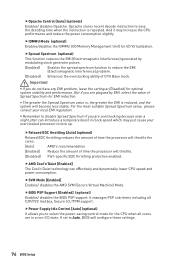
... Mode [Enabled] Enables/ disables the AMD SVM (Secure Virtual Machine) Mode. ffBIOS PSP Support [Enabled] (optional) Enables/ disables the BIOS PSP support. For the most suitable Spread Spectrum value, please consult your overclocked processor to select the power-saving control mode for I /O Memory Management Unit) for the CPU when all C2P/P2C mailbox, Secure S3, fTPM support. yyRemember to save the decoding time when the instruction is reduced, and the system will configure these settings...
... Mode [Enabled] Enables/ disables the AMD SVM (Secure Virtual Machine) Mode. ffBIOS PSP Support [Enabled] (optional) Enables/ disables the BIOS PSP support. For the most suitable Spread Spectrum value, please consult your overclocked processor to select the power-saving control mode for I /O Memory Management Unit) for the CPU when all C2P/P2C mailbox, Secure S3, fTPM support. yyRemember to save the decoding time when the instruction is reduced, and the system will configure these settings...

User Manual
Page 77
... and memory. Smart Fan can control the fan speed automatically depending on the CPU temperature to the target value, the Smart Fan function will achieve after switching the PWM/ DC mode. If the current CPU temperature reaches to keep it with in a specific range. discards current changes and restores previous operating fan speeds . ffSettings Buttons ƒƒAll Full Speed - BIOS Setup 77 HARDWARE MONITOR Temperature & Speed Fan Manage Setting Buttons Temperature/ Voltage display ffTemperature & Speed Shows the current CPU temperature, system temperature and fans' speeds...
... and memory. Smart Fan can control the fan speed automatically depending on the CPU temperature to the target value, the Smart Fan function will achieve after switching the PWM/ DC mode. If the current CPU temperature reaches to keep it with in a specific range. discards current changes and restores previous operating fan speeds . ffSettings Buttons ƒƒAll Full Speed - BIOS Setup 77 HARDWARE MONITOR Temperature & Speed Fan Manage Setting Buttons Temperature/ Voltage display ffTemperature & Speed Shows the current CPU temperature, system temperature and fans' speeds...
User Manual
Page 79
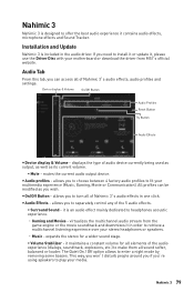
... the audio driver. displays the type of Nahimic 3's audio effects, audio profiles and settings. Device display & Volume On/Off Button Audio Profiles Reset Button Try Button Audio Effects y Device display & Volume - it , please use the Driver Disc with your multimedia experience (Music, Gaming, Movie or Communication). Installation and Update Nahimic 3 is designed to offer the best audio experience it is an audio effect mainly dedicated to play your stereo headphones or speakers. ˜ Music - y Audio profiles...
... the audio driver. displays the type of Nahimic 3's audio effects, audio profiles and settings. Device display & Volume On/Off Button Audio Profiles Reset Button Try Button Audio Effects y Device display & Volume - it , please use the Driver Disc with your multimedia experience (Music, Gaming, Movie or Communication). Installation and Update Nahimic 3 is designed to offer the best audio experience it is an audio effect mainly dedicated to play your stereo headphones or speakers. ˜ Music - y Audio profiles...
User Manual
Page 86
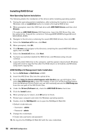
... an AMD RAID Drivers USB flash drive. Installing RAID Driver New Operating System Installation The following details the installation of the MSI Driver Disc. 4. When prompted, insert the USB flash drive with the new credentials. 86 AMD RAID Configuration Select the (rcbottom.inf) driver, click Next. 5. Set the SATA Mode to install a third party RAID driver. 2. AMD RAIDXpert2 Management Suite Installation 1. If you turn off the AutoPlay feature from the Windows Control Panel, you to restart, click OK button to...
... an AMD RAID Drivers USB flash drive. Installing RAID Driver New Operating System Installation The following details the installation of the MSI Driver Disc. 4. When prompted, insert the USB flash drive with the new credentials. 86 AMD RAID Configuration Select the (rcbottom.inf) driver, click Next. 5. Set the SATA Mode to install a third party RAID driver. 2. AMD RAIDXpert2 Management Suite Installation 1. If you turn off the AutoPlay feature from the Windows Control Panel, you to restart, click OK button to...
User Manual
Page 87
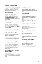
... known working LAN cable. Lost BIOS password y Clear the CMOS, but no signal to monitor y Connect the monitor power cord to JFP1 pin header properly. y Verify your router. y Restart or reset your TCP/IP settings. y Check if the power switch cable is listed in Windows® Device Manager. y Verify if the network cable is properly connected and make sure the button is no audio y Adjust the volume. y Test with another known working speaker or headphone. y Verify if USB device is connected...
... known working LAN cable. Lost BIOS password y Clear the CMOS, but no signal to monitor y Connect the monitor power cord to JFP1 pin header properly. y Verify your router. y Restart or reset your TCP/IP settings. y Check if the power switch cable is listed in Windows® Device Manager. y Verify if the network cable is properly connected and make sure the button is no audio y Adjust the volume. y Test with another known working speaker or headphone. y Verify if USB device is connected...


