User Manual
Page 13
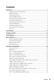
...Quick Start...1 Preparing Tools and Components 1 Safety Information 2 Installing a Processor 3 Installing DDR4 memory 5 Connecting the Front Panel Header 6 Installing the Motherboard 7 Connecting the Power Connectors 8 Installing SATA Drives 9 Installing a Graphics Card 10 Connecting Peripheral Devices 11 Power On...12 Specifications...15 Package contents 22 Block Diagram ...23 Rear I/O Panel...24 LAN Port LED Status Table 24 Audio Ports Configuration 24 Realtek Audio Console 25 Installing Antennas 27 Overview of Components 28 Processor Socket 30 DIMM Slots...31 PCI_E1~4: PCIe...
...Quick Start...1 Preparing Tools and Components 1 Safety Information 2 Installing a Processor 3 Installing DDR4 memory 5 Connecting the Front Panel Header 6 Installing the Motherboard 7 Connecting the Power Connectors 8 Installing SATA Drives 9 Installing a Graphics Card 10 Connecting Peripheral Devices 11 Power On...12 Specifications...15 Package contents 22 Block Diagram ...23 Rear I/O Panel...24 LAN Port LED Status Table 24 Audio Ports Configuration 24 Realtek Audio Console 25 Installing Antennas 27 Overview of Components 28 Processor Socket 30 DIMM Slots...31 PCI_E1~4: PCIe...
User Manual
Page 14
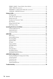
...RGB LED connectors 47 JCORSAIR1: CORSAIR Connector 48 Onboard LEDs...49 EZ Debug LED...49 LED_SW1: EZ LED Control 49 Debug Code LED...49 Hexadecimal Character Table 50 Boot Phases...50 Debug Code LED Table 50 ACPI States Codes 54 Installing OS, Drivers & Utilities 55 Installing Windows® 10 55 Installing Drivers 55 Installing Utilities 55 UEFI BIOS...56 BIOS Setup...57 Entering BIOS Setup 57 Resetting BIOS...58 Updating BIOS...58 EZ Mode...60 Advanced Mode ...63 SETTINGS Menu...64 OC Menu...66 M-FLASH Menu...69 OC PROFILE Menu 70 HARDWARE MONITOR Menu 71 AMD RAID Configuration...
...RGB LED connectors 47 JCORSAIR1: CORSAIR Connector 48 Onboard LEDs...49 EZ Debug LED...49 LED_SW1: EZ LED Control 49 Debug Code LED...49 Hexadecimal Character Table 50 Boot Phases...50 Debug Code LED Table 50 ACPI States Codes 54 Installing OS, Drivers & Utilities 55 Installing Windows® 10 55 Installing Drivers 55 Installing Utilities 55 UEFI BIOS...56 BIOS Setup...57 Entering BIOS Setup 57 Resetting BIOS...58 Updating BIOS...58 EZ Mode...60 Advanced Mode ...63 SETTINGS Menu...64 OC Menu...66 M-FLASH Menu...69 OC PROFILE Menu 70 HARDWARE MONITOR Menu 71 AMD RAID Configuration...

User Manual
Page 15
... Series processors (not compatible with AMD RyzenTM 5 3400G & RyzenTM 3 3200G) ▫▫1DPC 1R max speed 5100 MHz (QVL), Max. 5300 MHz ▫▫1DPC 2R max speed 4266 MHz (QVL) ∙∙Dual channel memory architecture ∙∙Supports non-ECC UDIMM memory ∙∙Supports ECC UDIMM memory (non-ECC mode) ∙∙Supports un-buffered memory * Please refer www.msi.com for more information on compatible memory. ∙∙1 x HDMI 2.1 port, supporting...
... Series processors (not compatible with AMD RyzenTM 5 3400G & RyzenTM 3 3200G) ▫▫1DPC 1R max speed 5100 MHz (QVL), Max. 5300 MHz ▫▫1DPC 2R max speed 4266 MHz (QVL) ∙∙Dual channel memory architecture ∙∙Supports non-ECC UDIMM memory ∙∙Supports ECC UDIMM memory (non-ECC mode) ∙∙Supports un-buffered memory * Please refer www.msi.com for more information on compatible memory. ∙∙1 x HDMI 2.1 port, supporting...

User Manual
Page 17
... Slot USB LAN Wireless LAN & Bluetooth® Audio Continued from previous page AMD Processor ∙∙1x PCIe 4.0/ 3.0 x16 slot (PCI_E1)* ▪▪Supports x16 or x8 mode** AMD B550 Chipset ∙∙1x PCIe 3.0 x16 slot , support x4 mode (PCI_E4)*** ∙∙2x PCIe 3.0 x1 slots (PCI_E2 & PCI_E3)**** * PCIe specifications may vary depending on next page Specifications 17 AMD Processor ▪▪4x USB 3.2 Gen 2 10Gbps ports(3 Type-A ports and 1 Type-C port) on the back panel AMD B550 chipset ▪▪1x USB 3.2 Gen 2 10Gbps Type-C internal connector...
... Slot USB LAN Wireless LAN & Bluetooth® Audio Continued from previous page AMD Processor ∙∙1x PCIe 4.0/ 3.0 x16 slot (PCI_E1)* ▪▪Supports x16 or x8 mode** AMD B550 Chipset ∙∙1x PCIe 3.0 x16 slot , support x4 mode (PCI_E4)*** ∙∙2x PCIe 3.0 x1 slots (PCI_E2 & PCI_E3)**** * PCIe specifications may vary depending on next page Specifications 17 AMD Processor ▪▪4x USB 3.2 Gen 2 10Gbps ports(3 Type-A ports and 1 Type-C port) on the back panel AMD B550 chipset ▪▪1x USB 3.2 Gen 2 10Gbps Type-C internal connector...

User Manual
Page 29
...PCI_E1~4 POWER1, RESET1 Processor Socket SATA1~6 Port Type Page Fan Connectors 43 Power Connectors 40 DIMM Slots 31 Front Audio Connector 39 Clear CMOS Jumper 45 Chassis Intrusion Connector 44 CORSAIR Connector 48 Front Panel Connectors 39 Addressable RGB LED connectors 47 RGB LED connector 46 TPM Module Connector 42 USB 3.2 Gen 2 10Gbps Type-C Connector 41 USB 3.2 Gen 1 5Gbps Connector 42 USB 2.0 Connectors 41 EZ LED Control 49 M.2 Slots (Key M) 36 PCIe Expansion Slots 32 Power Button, Reset Button 45 Socket AM4 30 SATA 6Gb/s Connectors 38 Overview of...
...PCI_E1~4 POWER1, RESET1 Processor Socket SATA1~6 Port Type Page Fan Connectors 43 Power Connectors 40 DIMM Slots 31 Front Audio Connector 39 Clear CMOS Jumper 45 Chassis Intrusion Connector 44 CORSAIR Connector 48 Front Panel Connectors 39 Addressable RGB LED connectors 47 RGB LED connector 46 TPM Module Connector 42 USB 3.2 Gen 2 10Gbps Type-C Connector 41 USB 3.2 Gen 1 5Gbps Connector 42 USB 2.0 Connectors 41 EZ LED Control 49 M.2 Slots (Key M) 36 PCIe Expansion Slots 32 Power Button, Reset Button 45 Socket AM4 30 SATA 6Gb/s Connectors 38 Overview of...

User Manual
Page 47
... LED Strip Connection 1 +5V D JRAINBOW connector Rainbow RGB LED extension cable Addressable RGB LED Fan Connection JRAINBOW connector 1 WS2812B Individually Addressable RGB LED strips 5V 1 System Fan connector Addressable RGB LED Fan ⚠⚠Important ∙∙The JRAINBOW connector supports up to 200 LEDs. ∙∙Always turn off the power supply and unplug the power cord from the power outlet before installing or removing the RGB LED strip. ∙∙Please use MSI's software to 75 LEDs...
... LED Strip Connection 1 +5V D JRAINBOW connector Rainbow RGB LED extension cable Addressable RGB LED Fan Connection JRAINBOW connector 1 WS2812B Individually Addressable RGB LED strips 5V 1 System Fan connector Addressable RGB LED Fan ⚠⚠Important ∙∙The JRAINBOW connector supports up to 200 LEDs. ∙∙Always turn off the power supply and unplug the power cord from the power outlet before installing or removing the RGB LED strip. ∙∙Please use MSI's software to 75 LEDs...

User Manual
Page 51
... - 77 PCH DXE Initialization (PCH module specific) 78 ACPI module initialization 79 CSM initialization 7A - 7F Reserved for future AMI DXE codes 90 Boot Device Selection (BDS) phase is started 91 Driver connecting is started 92 PCI Bus initialization is started 93 PCI Bus Hot Plug Controller Initialization 94 PCI Bus Enumeration 32 95 PCI Bus Request Resources Onboard LEDs 51 Configuring memory 2F Memory initialization (other) 31 Memory Installed 32 CPU post-memory initialization is started 33 CPU post-memory initialization. 2E Memory initialization.
... - 77 PCH DXE Initialization (PCH module specific) 78 ACPI module initialization 79 CSM initialization 7A - 7F Reserved for future AMI DXE codes 90 Boot Device Selection (BDS) phase is started 91 Driver connecting is started 92 PCI Bus initialization is started 93 PCI Bus Hot Plug Controller Initialization 94 PCI Bus Enumeration 32 95 PCI Bus Request Resources Onboard LEDs 51 Configuring memory 2F Memory initialization (other) 31 Memory Installed 32 CPU post-memory initialization is started 33 CPU post-memory initialization. 2E Memory initialization.
User Manual
Page 52
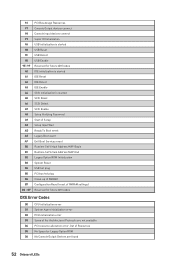
... A7 SCSI Enable A8 Setup Verifying Password A9 Start of Setup AB Setup Input Wait AD Ready To Boot event AE Legacy Boot event AF Exit Boot Services event B0 Runtime Set Virtual Address MAP Begin B1 Runtime Set Virtual Address MAP End B2 Legacy Option ROM Initialization B3 System Reset B4 USB hot plug B5 PCI bus hot plug B6 Clean-up of NVRAM B7 Configuration Reset (reset of the Architectural Protocols are found 52 Onboard LEDs BF...
... A7 SCSI Enable A8 Setup Verifying Password A9 Start of Setup AB Setup Input Wait AD Ready To Boot event AE Legacy Boot event AF Exit Boot Services event B0 Runtime Set Virtual Address MAP Begin B1 Runtime Set Virtual Address MAP End B2 Legacy Option ROM Initialization B3 System Reset B4 USB hot plug B5 PCI bus hot plug B6 Clean-up of NVRAM B7 Configuration Reset (reset of the Architectural Protocols are found 52 Onboard LEDs BF...
User Manual
Page 55
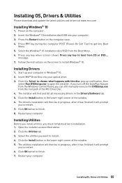
... the Windows® 10 installation disc/USB from the Windows Control Panel, you to finish. 8. message. 7. Follow the instructions on the computer case. 4. Click the Select to get into your optical drive. 3. The drivers installation will then be in progress, after it has finished it will find and list all necessary drivers in the Drivers/Software tab. 5. Select the utilities you must complete drivers installation. 1. Click OK button to boot...
... the Windows® 10 installation disc/USB from the Windows Control Panel, you to finish. 8. message. 7. Follow the instructions on the computer case. 4. Click the Select to get into your optical drive. 3. The drivers installation will then be in progress, after it has finished it will find and list all necessary drivers in the Drivers/Software tab. 5. Select the utilities you must complete drivers installation. 1. Click OK button to boot...
User Manual
Page 58
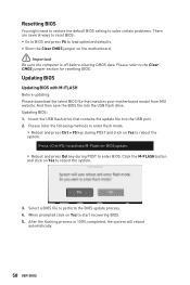
Updating BIOS Updating BIOS with M-FLASH Before updating: Please download the latest BIOS file that contains the update file into the USB flash drive. Insert the USB flash drive that matches your motherboard model from MSI website. Click the M-FLASH button and click on the motherboard. ⚠⚠Important Be sure the computer is 100% completed, the system will reboot automatically. 58 UEFI BIOS Resetting BIOS You might need to restore the default BIOS setting to solve certain problems. There are several...
Updating BIOS Updating BIOS with M-FLASH Before updating: Please download the latest BIOS file that contains the update file into the USB flash drive. Insert the USB flash drive that matches your motherboard model from MSI website. Click the M-FLASH button and click on the motherboard. ⚠⚠Important Be sure the computer is 100% completed, the system will reboot automatically. 58 UEFI BIOS Resetting BIOS You might need to restore the default BIOS setting to solve certain problems. There are several...
User Manual
Page 59
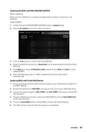
.... Updating the BIOS with Flash BIOS Button 1. Click Next and choose In Windows mode. Please download the latest BIOS file that contains the MSI.ROM file into the Flash BIOS Port on Download icon to download and install the latest BIOS file. 5. Click on Advance button. 3. Updating BIOS with MSI DRAGON CENTER Before updating: Make sure the LAN driver is already installed and the internet connection is set properly. Press the Flash BIOS Button to the root of your motherboard model from the MSI® website. 2. UEFI BIOS 59...
.... Updating the BIOS with Flash BIOS Button 1. Click Next and choose In Windows mode. Please download the latest BIOS file that contains the MSI.ROM file into the Flash BIOS Port on Download icon to download and install the latest BIOS file. 5. Click on Advance button. 3. Updating BIOS with MSI DRAGON CENTER Before updating: Make sure the LAN driver is already installed and the internet connection is set properly. Press the Flash BIOS Button to the root of your motherboard model from the MSI® website. 2. UEFI BIOS 59...
User Manual
Page 61
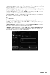
... temperature, MB/ CPU type, memory size, CPU/ DDR voltage, BIOS version and build date. ∙∙ Boot device priority bar - click on this button or press the F3 key to manually control the fan speed by clicking on this button to enter the Hardware Monitor menu that provides the way to show the Favorites window. click on these buttons. click on this button to create personal BIOS menu where you can save and access favorite/ frequently-used BIOS setting items. UEFI BIOS...
... temperature, MB/ CPU type, memory size, CPU/ DDR voltage, BIOS version and build date. ∙∙ Boot device priority bar - click on this button or press the F3 key to manually control the fan speed by clicking on this button to enter the Hardware Monitor menu that provides the way to show the Favorites window. click on these buttons. click on this button to create personal BIOS menu where you can save and access favorite/ frequently-used BIOS setting items. UEFI BIOS...
User Manual
Page 63
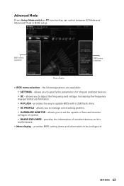
...;M-FLASH - allows you to be configured. provides the information of system. ▪▪BOARD EXPLORER - allows you to manage overclocking profiles. ▪▪HARDWARE MONITOR - the following options are available: ▪▪SETTINGS - Advanced Mode Press Setup Mode switch or F7 function key can switch between EZ Mode and Advanced Mode in BIOS setup. provides BIOS setting items and information to set the speeds of fans and monitor voltages of installed devices on this motherboard. ∙∙ Menu display...
...;M-FLASH - allows you to be configured. provides the information of system. ▪▪BOARD EXPLORER - allows you to manage overclocking profiles. ▪▪HARDWARE MONITOR - the following options are available: ▪▪SETTINGS - Advanced Mode Press Setup Mode switch or F7 function key can switch between EZ Mode and Advanced Mode in BIOS setup. provides BIOS setting items and information to set the speeds of fans and monitor voltages of installed devices on this motherboard. ∙∙ Menu display...
User Manual
Page 64
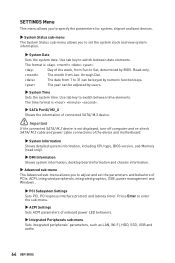
through Dec. Use tab key to switch between time elements. The format is not displayed, turn off computer and re-check SATA/ M.2 cable and power cable connections of the device and motherboard. ▶▶System Information Shows detailed system information, including CPU type, BIOS version, and Memory (read only). ▶▶DMI Information Shows system information, desktop board information and chassis information. ▶▶Advanced sub-menu The Advanced sub-menu allows you...
through Dec. Use tab key to switch between time elements. The format is not displayed, turn off computer and re-check SATA/ M.2 cable and power cable connections of the device and motherboard. ▶▶System Information Shows detailed system information, including CPU type, BIOS version, and Memory (read only). ▶▶DMI Information Shows system information, desktop board information and chassis information. ▶▶Advanced sub-menu The Advanced sub-menu allows you...
User Manual
Page 65
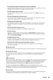
... system power consumption in this menu to load the BIOS default values or factory default settings into the BIOS and exit the BIOS setup utility with IGP. ▶▶USB Configuration sub-menu Sets the onboard USB controller and device function. Type the password then press Enter. This sub-menu is functioning properly. A message will replace any previous set the administrator password and the user password for system security. Secure Erase+ is being disabled. You will appear on the screen...
... system power consumption in this menu to load the BIOS default values or factory default settings into the BIOS and exit the BIOS setup utility with IGP. ▶▶USB Configuration sub-menu Sets the onboard USB controller and device function. Type the password then press Enter. This sub-menu is functioning properly. A message will replace any previous set the administrator password and the user password for system security. Secure Erase+ is being disabled. You will appear on the screen...
User Manual
Page 66
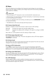
... UEFI BIOS This item appears when a CPU that is installed. ▶▶A-XMP [Disabled] Please enable A-XMP or select a profile of memory module for overclocking the memory. This item only appears when a CPU that supports Turbo Boost is installed. ▶▶CPU Ratio [Auto] Sets the CPU ratio that support this function. ▶▶Advanced CPU Configuration Press Enter to enter the sub-menu. You may become unstable or unbootable after changing the...
... UEFI BIOS This item appears when a CPU that is installed. ▶▶A-XMP [Disabled] Please enable A-XMP or select a profile of memory module for overclocking the memory. This item only appears when a CPU that supports Turbo Boost is installed. ▶▶CPU Ratio [Auto] Sets the CPU ratio that support this function. ▶▶Advanced CPU Configuration Press Enter to enter the sub-menu. You may become unstable or unbootable after changing the...
User Manual
Page 67
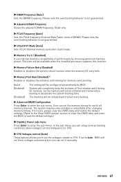
... DRAM). User can improve memory compatibility or performance by BIOS. If set to Auto, BIOS will set it occurs, please clear the CMOS data and restore the default settings. (Refer to the Clear CMOS jumper section to clear the CMOS data, and enter the BIOS to load the default settings.) ▶▶DigitALL Power sub-menu Press Enter to enter the sub-menu. ▶▶DRAM Frequency [Auto] Sets the DRAM frequency. Please note the overclocking behavior is not guaranteed. ▶▶UCLK DIV1 Mode [Auto] Sets UCLK (Internal memory controller clock) mode...
... DRAM). User can improve memory compatibility or performance by BIOS. If set to Auto, BIOS will set it occurs, please clear the CMOS data and restore the default settings. (Refer to the Clear CMOS jumper section to clear the CMOS data, and enter the BIOS to load the default settings.) ▶▶DigitALL Power sub-menu Press Enter to enter the sub-menu. ▶▶DRAM Frequency [Auto] Sets the DRAM frequency. Please note the overclocking behavior is not guaranteed. ▶▶UCLK DIV1 Mode [Auto] Sets UCLK (Internal memory controller clock) mode...
User Manual
Page 69
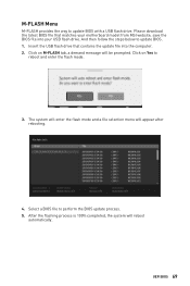
Please download the latest BIOS file that contains the update file into your motherboard model from MSI website, save the BIOS file into the computer. 2. Click on M-FLASH tab, a demand message will be prompted. The system will enter the flash mode and a file selection menu will reboot automatically. Select a BIOS file to update BIOS with a USB flash drive. UEFI BIOS 69 After the flashing process is 100% completed, the system will appear after rebooting. 4. Click on Yes...
Please download the latest BIOS file that contains the update file into your motherboard model from MSI website, save the BIOS file into the computer. 2. Click on M-FLASH tab, a demand message will be prompted. The system will enter the flash mode and a file selection menu will reboot automatically. Select a BIOS file to update BIOS with a USB flash drive. UEFI BIOS 69 After the flashing process is 100% completed, the system will appear after rebooting. 4. Click on Yes...
User Manual
Page 77
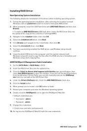
...) driver, click Next. 5. Leave the disk/ USB drive in \\Storage\AMD\ 3. exe from the Windows Control Panel, you to restart, click OK button to copy the files after selecting the location to install Windows click on Load driver button to RAID Mode in BIOS 2. Double-click the RAIDXpert2 icon to the rcbottom folder, then click OK. 4. Copy all the contents in the computer until the system reboots itself. Insert the MSI Driver...
...) driver, click Next. 5. Leave the disk/ USB drive in \\Storage\AMD\ 3. exe from the Windows Control Panel, you to restart, click OK button to copy the files after selecting the location to install Windows click on Load driver button to RAID Mode in BIOS 2. Double-click the RAIDXpert2 icon to the rcbottom folder, then click OK. 4. Copy all the contents in the computer until the system reboots itself. Insert the MSI Driver...

User Manual
Page 78
... pin header properly. ∙∙Verify the Clear CMOS jumper JBAT1 is set to the motherboard? ∙∙Some power supply units have a power button on the rear side, make sure the LAN port LEDs are connected from the power supply to Keep DATA. ∙∙Test with another known working speaker or headphone. The USB device is listed in the BIOS. The power is turned on the motherboard rear IO panel. The computer does not boot after updating...
... pin header properly. ∙∙Verify the Clear CMOS jumper JBAT1 is set to the motherboard? ∙∙Some power supply units have a power button on the rear side, make sure the LAN port LEDs are connected from the power supply to Keep DATA. ∙∙Test with another known working speaker or headphone. The USB device is listed in the BIOS. The power is turned on the motherboard rear IO panel. The computer does not boot after updating...


