
User Guide
Page 4
... FCC Rules. However, there is no guarantee that may cause harmful interference to radio communications. VOIR LANOTICE D'INSTALLATIONAVANT DE RACCORDER AU RESEAU. Micro-Star International MS-7411 This device complies with the instructions, may cause undesired operation. Reorient or relocate the receiving antenna. Notice 1 The changes or modifications not expressly approved by...
... FCC Rules. However, there is no guarantee that may cause harmful interference to radio communications. VOIR LANOTICE D'INSTALLATIONAVANT DE RACCORDER AU RESEAU. Micro-Star International MS-7411 This device complies with the instructions, may cause undesired operation. Reorient or relocate the receiving antenna. Notice 1 The changes or modifications not expressly approved by...

User Guide
Page 9
Designed to fit the advanced AMD® PhenomTM, AthlonTM 64/ 64 FX/ 64 X2 and SempronTM processors in the socket AM2/ AM2+ package, the Media Live DIVA delivers a high performance and professional desktop platform solution. 1-1 The Media Live DIVA is based on AMD® RS780M & SB700 chipsets for choosing the Media Live DIVA (MS-7411 V1.X) Micro-ATX mainboard. Getting Started Chapter 1 Getting Started Thank you for optimal system efficiency.
Designed to fit the advanced AMD® PhenomTM, AthlonTM 64/ 64 FX/ 64 X2 and SempronTM processors in the socket AM2/ AM2+ package, the Media Live DIVA delivers a high performance and professional desktop platform solution. 1-1 The Media Live DIVA is based on AMD® RS780M & SB700 chipsets for choosing the Media Live DIVA (MS-7411 V1.X) Micro-ATX mainboard. Getting Started Chapter 1 Getting Started Thank you for optimal system efficiency.
User Guide
Page 10
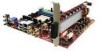
... integrated by AMD® SB700 - t w / i ndex . Supports storage and data transfers up to 3 Gb/s RAID - t w / i nde x . Supports 4 SATA devices - MS-7411 Mainboard Mainboard Specifications Processor - c om. South Bridge: AMD® SB700 chipset Mem or y - c om. DDR2 400/ 533/ 667/ 800 SDRAM (240-Pin/ 1.8 V) - 4 DDR2 DIMM slots (...
... integrated by AMD® SB700 - t w / i ndex . Supports storage and data transfers up to 3 Gb/s RAID - t w / i nde x . Supports 4 SATA devices - MS-7411 Mainboard Mainboard Specifications Processor - c om. South Bridge: AMD® SB700 chipset Mem or y - c om. DDR2 400/ 533/ 667/ 800 SDRAM (240-Pin/ 1.8 V) - 4 DDR2 DIMM slots (...

User Guide
Page 12
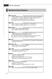
MS-7411 Mainboard Mainboard Layout JRCA1 CP U _ FAN 1 T: VGA1 B: SPDIFOUT SP D IF IN CIR1 JCOM HDMI1 T: I1394 B: USB T: LAN B: USB JRCA2 SUBOUT JPW1 JRCA3 S YS _ FA N1 PCIE1_X1 PCIE16_X1 PCIE1_X2 PCIE1_X3 JAUD1 CD_IN AMD RS780M DIMM1 DIMM2 DIMM3 DIMM4 SATA2 SATA3 SATA1 SATA4 AMD SB700 D AE3 -SO LT B AT T + J1394_2 JUSB0 JUSB3 CLR_CMOS2 JFP1 JUSB2 JUSB1 PWR_ FAN1 IDE 1 AT X 1 Media Live DIVA (MS-7411 V1.X) Micro-ATX Mainboard 1-4
MS-7411 Mainboard Mainboard Layout JRCA1 CP U _ FAN 1 T: VGA1 B: SPDIFOUT SP D IF IN CIR1 JCOM HDMI1 T: I1394 B: USB T: LAN B: USB JRCA2 SUBOUT JPW1 JRCA3 S YS _ FA N1 PCIE1_X1 PCIE16_X1 PCIE1_X2 PCIE1_X3 JAUD1 CD_IN AMD RS780M DIMM1 DIMM2 DIMM3 DIMM4 SATA2 SATA3 SATA1 SATA4 AMD SB700 D AE3 -SO LT B AT T + J1394_2 JUSB0 JUSB3 CLR_CMOS2 JFP1 JUSB2 JUSB1 PWR_ FAN1 IDE 1 AT X 1 Media Live DIVA (MS-7411 V1.X) Micro-ATX Mainboard 1-4
User Guide
Page 18
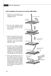
.... If the CPU is being closed, always close the lever. Gold arrow Press down firmly into the socket and can only fit in the picture. MS-7411 Mainboard CPU Installation Procedures for the gold arrow on top of the correct installation procedures may cause permanent damage to make sure the CPU is...
.... If the CPU is being closed, always close the lever. Gold arrow Press down firmly into the socket and can only fit in the picture. MS-7411 Mainboard CPU Installation Procedures for the gold arrow on top of the correct installation procedures may cause permanent damage to make sure the CPU is...

User Guide
Page 20
... performance. Enabling Dual-Channel mode can transmit and receive data with two data bus lines simultaneously. Please refer to the following illustrations for memory modules. MS-7411 Mainboard Memory These DIMM slots are intended for population rules under Dual-Channel mode. For more information on compatible components, please visit http://global...
... performance. Enabling Dual-Channel mode can transmit and receive data with two data bus lines simultaneously. Please refer to the following illustrations for memory modules. MS-7411 Mainboard Memory These DIMM slots are intended for population rules under Dual-Channel mode. For more information on compatible components, please visit http://global...

User Guide
Page 22
... power to avoid wrong installation. Power supply of 350 watts (and above) is also a foolproof design on pin 11, 12, 23 & 24 to the CPU. MS-7411 Mainboard Power Supply ATX 24-Pin Power Connector: ATX1 This connector allows you to ensure stable operation of the mainboard. 2. ATX1 Pin Definition 12 24...
... power to avoid wrong installation. Power supply of 350 watts (and above) is also a foolproof design on pin 11, 12, 23 & 24 to the CPU. MS-7411 Mainboard Power Supply ATX 24-Pin Power Connector: ATX1 This connector allows you to ensure stable operation of the mainboard. 2. ATX1 Pin Definition 12 24...

User Guide
Page 24
IDE1 Important If you install two IDE devices on the same cable, you must configure the drives separately to IDE device's documentation supplied by setting jumpers. MS-7411 Mainboard Connector IDE Connector: IDE1 This connector supports IDE hard disk drives, optical disk drives and other IDE devices. Refer to master/ slave mode by the vendors for jumper setting instructions. 2-10
IDE1 Important If you install two IDE devices on the same cable, you must configure the drives separately to IDE device's documentation supplied by setting jumpers. MS-7411 Mainboard Connector IDE Connector: IDE1 This connector supports IDE hard disk drives, optical disk drives and other IDE devices. Refer to master/ slave mode by the vendors for jumper setting instructions. 2-10

User Guide
Page 26
... with 3 or 4 pins are both available for proper CPU cooling fan. 2. CONTROL SE NS OR +1 2V GND CPU_FAN1 PWR_FAN1 GND +12V SENSOR Control SYS_FAN1 Important 1. MS-7411 Mainboard Serial Port Connector: JCOM This connector is a 16550A high speed communications port that the red wire is Ground and should be connected to GND...
... with 3 or 4 pins are both available for proper CPU cooling fan. 2. CONTROL SE NS OR +1 2V GND CPU_FAN1 PWR_FAN1 GND +12V SENSOR Control SYS_FAN1 Important 1. MS-7411 Mainboard Serial Port Connector: JCOM This connector is a 16550A high speed communications port that the red wire is Ground and should be connected to GND...

User Guide
Page 28
MS-7411 Mainboard Front USB Connector: JUSB0, JUSB1, JUSB2, JUSB3 This connector, compliant with Intel® I/O Connectivity Design Guide, is ideal for connecting high-speed USB interface ...
MS-7411 Mainboard Front USB Connector: JUSB0, JUSB1, JUSB2, JUSB3 This connector, compliant with Intel® I/O Connectivity Design Guide, is ideal for connecting high-speed USB interface ...

User Guide
Page 30
If you want to clear the system configuration, set the jumper to clear data. 1 1 3 CLR_CMOS2 Keep Data 1 3 Clear Data Important You can automatically boot OS every time it will damage the mainboard. 2-16 Avoid clearing the CMOS while the system is turned on ; Then return to keep the dasta of system configuration. MS-7411 Mainboard Jumper Clear CMOS Jumper: CLR_CMOS2 There is off. W ith the CMOS RAM, the system can clear CMOS by shorting 2-3 pin while the system is a CMOS RAM onboard that has a power supply from an external battery to 1-2 pin position. it is on .
If you want to clear the system configuration, set the jumper to clear data. 1 1 3 CLR_CMOS2 Keep Data 1 3 Clear Data Important You can automatically boot OS every time it will damage the mainboard. 2-16 Avoid clearing the CMOS while the system is turned on ; Then return to keep the dasta of system configuration. MS-7411 Mainboard Jumper Clear CMOS Jumper: CLR_CMOS2 There is off. W ith the CMOS RAM, the system can clear CMOS by shorting 2-3 pin while the system is a CMOS RAM onboard that has a power supply from an external battery to 1-2 pin position. it is on .

User Guide
Page 34
... Test) process. V1.0 refers to the BIOS version. 071508 refers to enter Setup, restart the system by simultaneously pressing , and keys. MS-7411 Mainboard Entering Setup Power on the screen, press key to enter Setup. You may be slightly different from the latest BIOS and should be held.... 6th digit refers to the chipset as I = INTEL, A = AMD, N = NVIDIA and V = VIA. 7th - 8th digit refers to the customer as MS = all standard customers. The items under continuous update for reference only. 2. Important 1. Therefore, the description may also restart the system by turning it OFF and...
... Test) process. V1.0 refers to the BIOS version. 071508 refers to enter Setup, restart the system by simultaneously pressing , and keys. MS-7411 Mainboard Entering Setup Power on the screen, press key to enter Setup. You may be slightly different from the latest BIOS and should be held.... 6th digit refers to the chipset as I = INTEL, A = AMD, N = NVIDIA and V = VIA. 7th - 8th digit refers to the customer as MS = all standard customers. The items under continuous update for reference only. 2. Important 1. Therefore, the description may also restart the system by turning it OFF and...

User Guide
Page 36
Power Use this menu to specify the priority of special enhanced features available on your system's performance. MS-7411 Mainboard The Menu Bar Main Use this menu for power management. Chipset Use this menu to specify your settings for basic system configurations, such as ...
Power Use this menu to specify the priority of special enhanced features available on your system's performance. MS-7411 Mainboard The Menu Bar Main Use this menu for power management. Chipset Use this menu to specify your settings for basic system configurations, such as ...

User Guide
Page 38
MS-7411 Mainboard Advanced WARNING: Setting wrong values in below sections may cause system to malfunction. CPU Configuration Press and the following sub-menu appears: 3-6
MS-7411 Mainboard Advanced WARNING: Setting wrong values in below sections may cause system to malfunction. CPU Configuration Press and the following sub-menu appears: 3-6
User Guide
Page 40
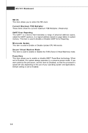
... a device that the processor's speed will vary depending on page tables in a conserve power mode. PowerNow This item allows you to select the NB clock. MS-7411 Mainboard NB Clk This item allows you to enable or disable AMD® PowerNow technology. W hen set this item to Disabled, so that translates a range...
... a device that the processor's speed will vary depending on page tables in a conserve power mode. PowerNow This item allows you to select the NB clock. MS-7411 Mainboard NB Clk This item allows you to enable or disable AMD® PowerNow technology. W hen set this item to Disabled, so that translates a range...

User Guide
Page 42
... [Enabled] only if your disk status to predict hard disk failure. In Auto mode, the system automatically determines the best mode for the hard disks. MS-7411 Mainboard LBA/ Large Mode This item allows you to enable or disable the DMA (Direct Memory Access) mode. Block (Multi-Sector Transfer) W hen the setting...
... [Enabled] only if your disk status to predict hard disk failure. In Auto mode, the system automatically determines the best mode for the hard disks. MS-7411 Mainboard LBA/ Large Mode This item allows you to enable or disable the DMA (Direct Memory Access) mode. Block (Multi-Sector Transfer) W hen the setting...

User Guide
Page 44
..., VCC, +12.0V, CPU Core These items display the current status of all of the monitored hardware devices and components such as CPU voltages. 3-12 MS-7411 Mainboard Hardware Health Configuration Press and the following sub-menu appears: H/W Health Function This setting enables Hardware Health Monitoring Device. CPU/ System/ Power FAN Mode...
..., VCC, +12.0V, CPU Core These items display the current status of all of the monitored hardware devices and components such as CPU voltages. 3-12 MS-7411 Mainboard Hardware Health Configuration Press and the following sub-menu appears: H/W Health Function This setting enables Hardware Health Monitoring Device. CPU/ System/ Power FAN Mode...

User Guide
Page 46
... headless mode, both BIOS and operating system must support headless operation. W hen enabled, the BIOS will update the FACP to indicate support for headless operation. MS-7411 Mainboard ACPI Version Features This item is used to Enable or Disable support ACPI APIC.
... headless mode, both BIOS and operating system must support headless operation. W hen enabled, the BIOS will update the FACP to indicate support for headless operation. MS-7411 Mainboard ACPI Version Features This item is used to Enable or Disable support ACPI APIC.

User Guide
Page 48
... to use any USB 2.0 device in the operating system that does not support or have any USB 1.1/ 2.0 driver installed, such as DOS and SCO Unix. MS-7411 Mainboard USB Configuration Press and the following sub-menu appears: 3-16
... to use any USB 2.0 device in the operating system that does not support or have any USB 1.1/ 2.0 driver installed, such as DOS and SCO Unix. MS-7411 Mainboard USB Configuration Press and the following sub-menu appears: 3-16

User Guide
Page 50
MS-7411 Mainboard Boot Boot Settings Configuration Press and the following sub-menu appears: Quick Boot Setting the item to [Enabled] allows the system to boot within 5 seconds since it will skip some check items. Quiet Boot If set to [enabled] the OS boots straight to the GUI without showing the POST screen, if set to [disabled] it boots to the POST first. 3-18
MS-7411 Mainboard Boot Boot Settings Configuration Press and the following sub-menu appears: Quick Boot Setting the item to [Enabled] allows the system to boot within 5 seconds since it will skip some check items. Quiet Boot If set to [enabled] the OS boots straight to the GUI without showing the POST screen, if set to [disabled] it boots to the POST first. 3-18


