
User Guide
Page 2
...2000/NT/XP are the properties of AMD Corporation. AMI® is a registered trademark of M ICRO-STAR INTERNATIONAL. Visit the MSI website at http://ocss.msi.com.tw. Copyright Notice The material in this document, but no solution can be obtained from the user's manual, please contact ... of Phoenix Technologies Ltd. We take every care in the United States and/or other information. Contact our technical staff at http://global.msi.com.tw/index.php? Netware® is a registered trademark of purchase or local distributor. Revision History Revision V1.1 Revision History First ...
...2000/NT/XP are the properties of AMD Corporation. AMI® is a registered trademark of M ICRO-STAR INTERNATIONAL. Visit the MSI website at http://ocss.msi.com.tw. Copyright Notice The material in this document, but no solution can be obtained from the user's manual, please contact ... of Phoenix Technologies Ltd. We take every care in the United States and/or other information. Contact our technical staff at http://global.msi.com.tw/index.php? Netware® is a registered trademark of purchase or local distributor. Revision History Revision V1.1 Revision History First ...

User Guide
Page 3
Make sure the voltage of the following situations arises, get it work well or you can not step on card or module. 9. Place the power cord such a way that could damage or cause electrical s h oc k . 11. Always Unplug the Power Cord before setting it . DO NOT LEAVETHIS EQUIPMENT INANENVIRONMENT UNCONDITIONED, STORAGE TEMPERATURE ABOVE 600 C (1400F), IT MAYDAMAGE THE EQUIPMENT. Do not place anything over the power cord. 8. All cautions and warnings on the equipment should be - Never pour any of the power source and adjust properly 110/220V be noted. 10. CAUTION: Danger of...
Make sure the voltage of the following situations arises, get it work well or you can not step on card or module. 9. Place the power cord such a way that could damage or cause electrical s h oc k . 11. Always Unplug the Power Cord before setting it . DO NOT LEAVETHIS EQUIPMENT INANENVIRONMENT UNCONDITIONED, STORAGE TEMPERATURE ABOVE 600 C (1400F), IT MAYDAMAGE THE EQUIPMENT. Do not place anything over the power cord. 8. All cautions and warnings on the equipment should be - Never pour any of the power source and adjust properly 110/220V be noted. 10. CAUTION: Danger of...

User Guide
Page 4
However, there is no guarantee that may cause undesired operation. Consult the dealer or an experienced radio/television technician for compliance could void the user's authority to provide reasonable protection against harmful interference in accordance with Part 15 of the FCC Rules. Micro-Star International MS-7411 This device complies with the instructions, may not cause harmful interference, and (2) this equipment does cause harmful interference to radio or television reception, which the receiver is connected. This equipment generates, uses and can be used in a ...
However, there is no guarantee that may cause undesired operation. Consult the dealer or an experienced radio/television technician for compliance could void the user's authority to provide reasonable protection against harmful interference in accordance with Part 15 of the FCC Rules. Micro-Star International MS-7411 This device complies with the instructions, may not cause harmful interference, and (2) this equipment does cause harmful interference to radio or television reception, which the receiver is connected. This equipment generates, uses and can be used in a ...

User Guide
Page 5
WEEE (Waste Electrical and Electronic Equipment) Statement v
WEEE (Waste Electrical and Electronic Equipment) Statement v

User Guide
Page 8
CONTENTS Copyright Notice...ii Trademarks...ii Revision History...ii Technical Support ii Safety Instructions iii FCC-B Radio Frequency Interference Statement iv WEEE (Waste Electrical and Electronic Equipment) Statement v Chapter 1 Getting Started 1-1 Mainboard Specifications 1-2 Mainboard Layout 1-4 Packing Checklist 1-5 Chapter 2 Hardware Setup 2-1 Quick Components Guide 2-2 CPU (Central Processing Unit 2-3 Memory...2-6 Power Supply 2-8 Back Panel...2-9 Connector...2-10 Jumper...2-16 Slot...2-17 Chapter 3 BIOS Setup 3-1 Entering Setup 3-2 The Menu Bar 3-4 Main...3-5 Advanced...
CONTENTS Copyright Notice...ii Trademarks...ii Revision History...ii Technical Support ii Safety Instructions iii FCC-B Radio Frequency Interference Statement iv WEEE (Waste Electrical and Electronic Equipment) Statement v Chapter 1 Getting Started 1-1 Mainboard Specifications 1-2 Mainboard Layout 1-4 Packing Checklist 1-5 Chapter 2 Hardware Setup 2-1 Quick Components Guide 2-2 CPU (Central Processing Unit 2-3 Memory...2-6 Power Supply 2-8 Back Panel...2-9 Connector...2-10 Jumper...2-16 Slot...2-17 Chapter 3 BIOS Setup 3-1 Entering Setup 3-2 The Menu Bar 3-4 Main...3-5 Advanced...

User Guide
Page 9
The Media Live DIVA is based on AMD® RS780M & SB700 chipsets for choosing the Media Live DIVA (MS-7411 V1.X) Micro-ATX mainboard. Designed to fit the advanced AMD® PhenomTM, AthlonTM 64/ 64 FX/ 64 X2 and SempronTM processors in the socket AM2/ AM2+ package, the Media Live DIVA delivers a high performance and professional desktop platform solution. 1-1 Getting Started Chapter 1 Getting Started Thank you for optimal system efficiency.
The Media Live DIVA is based on AMD® RS780M & SB700 chipsets for choosing the Media Live DIVA (MS-7411 V1.X) Micro-ATX mainboard. Designed to fit the advanced AMD® PhenomTM, AthlonTM 64/ 64 FX/ 64 X2 and SempronTM processors in the socket AM2/ AM2+ package, the Media Live DIVA delivers a high performance and professional desktop platform solution. 1-1 Getting Started Chapter 1 Getting Started Thank you for optimal system efficiency.
User Guide
Page 10
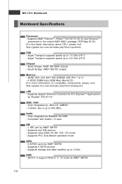
c om. North Bridge: AMD® RS780M chipset - ms i. SATA1~4 support RAID 0/ 1/ 10 m ode by Realtek® RTL8111C IEEE 1394 - Supports AMD® PhenomTM, AthlonTM 64/ 64 FX/ 64 X2 and SempronTM processors in the socket AM2/ AM2+ package (TDP Max 95 W ) (For the latest information about CPU, please visit ht t p: / / g loba l. php?f unc = c puf orm) FSB - Hyper Transport supports speed up to 2.6 GHz (HT3) Chipset - c om. Supports Gigabit Ethernet Controller for PCI ExpressTM Applications by AMD® SB700 1-2 Supports 4 SATA devices - DDR2 400/ 533/ 667/ 800 SDRAM (240-Pin...
c om. North Bridge: AMD® RS780M chipset - ms i. SATA1~4 support RAID 0/ 1/ 10 m ode by Realtek® RTL8111C IEEE 1394 - Supports AMD® PhenomTM, AthlonTM 64/ 64 FX/ 64 X2 and SempronTM processors in the socket AM2/ AM2+ package (TDP Max 95 W ) (For the latest information about CPU, please visit ht t p: / / g loba l. php?f unc = c puf orm) FSB - Hyper Transport supports speed up to 2.6 GHz (HT3) Chipset - c om. Supports Gigabit Ethernet Controller for PCI ExpressTM Applications by AMD® SB700 1-2 Supports 4 SATA devices - DDR2 400/ 533/ 667/ 800 SDRAM (240-Pin...

User Guide
Page 11
Micro-ATX (24.4 cm X 24.4 cm) Mounting - 8 mounting holes 1-3 Getting Started Connector Back Panel - 1 VGA port - 4 USB ports - 1 HDMI port - 1 IEEE 1394 port - 1 LAN jack - 5 audio RCA-in/ out jacks - 3 com ponent video-out jacks - 2 coaxial S/PDIF-in/ out jacks On-Board Pinheader/ Connector - 1 CD-in connector - 1 serial port connector - 4 USB pinheaders - 1 IEEE 1394 pinheader - 1 front panel audio pinheader - 1 CIR connector Slot - 1 PCI express x16 slot (For VGA card use only) - 1 PCI express x4 slot (For amplifier card use only) - 3 PCI express x1 slots Form Factor -
Micro-ATX (24.4 cm X 24.4 cm) Mounting - 8 mounting holes 1-3 Getting Started Connector Back Panel - 1 VGA port - 4 USB ports - 1 HDMI port - 1 IEEE 1394 port - 1 LAN jack - 5 audio RCA-in/ out jacks - 3 com ponent video-out jacks - 2 coaxial S/PDIF-in/ out jacks On-Board Pinheader/ Connector - 1 CD-in connector - 1 serial port connector - 4 USB pinheaders - 1 IEEE 1394 pinheader - 1 front panel audio pinheader - 1 CIR connector Slot - 1 PCI express x16 slot (For VGA card use only) - 1 PCI express x4 slot (For amplifier card use only) - 3 PCI express x1 slots Form Factor -

User Guide
Page 12
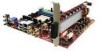
MS-7411 Mainboard Mainboard Layout JRCA1 CP U _ FAN 1 T: VGA1 B: SPDIFOUT SP D IF IN CIR1 JCOM HDMI1 T: I1394 B: USB T: LAN B: USB JRCA2 SUBOUT JPW1 JRCA3 S YS _ FA N1 PCIE1_X1 PCIE16_X1 PCIE1_X2 PCIE1_X3 JAUD1 CD_IN AMD RS780M DIMM1 DIMM2 DIMM3 DIMM4 SATA2 SATA3 SATA1 SATA4 AMD SB700 D AE3 -SO LT B AT T + J1394_2 JUSB0 JUSB3 CLR_CMOS2 JFP1 JUSB2 JUSB1 PWR_ FAN1 IDE 1 AT X 1 Media Live DIVA (MS-7411 V1.X) Micro-ATX Mainboard 1-4
MS-7411 Mainboard Mainboard Layout JRCA1 CP U _ FAN 1 T: VGA1 B: SPDIFOUT SP D IF IN CIR1 JCOM HDMI1 T: I1394 B: USB T: LAN B: USB JRCA2 SUBOUT JPW1 JRCA3 S YS _ FA N1 PCIE1_X1 PCIE16_X1 PCIE1_X2 PCIE1_X3 JAUD1 CD_IN AMD RS780M DIMM1 DIMM2 DIMM3 DIMM4 SATA2 SATA3 SATA1 SATA4 AMD SB700 D AE3 -SO LT B AT T + J1394_2 JUSB0 JUSB3 CLR_CMOS2 JFP1 JUSB2 JUSB1 PWR_ FAN1 IDE 1 AT X 1 Media Live DIVA (MS-7411 V1.X) Micro-ATX Mainboard 1-4

User Guide
Page 13
Packing Checklist Getting Started MSI Mainboard MSI Driver/ Utility CD User's Guide Back I/O Shield Power Cable SATA Cable Standard Cable for IDE Devices Amplifier Card Speaker Connector * The pictures are for reference only and your packing contents may vary depending on the model you purchased. 1-5
Packing Checklist Getting Started MSI Mainboard MSI Driver/ Utility CD User's Guide Back I/O Shield Power Cable SATA Cable Standard Cable for IDE Devices Amplifier Card Speaker Connector * The pictures are for reference only and your packing contents may vary depending on the model you purchased. 1-5

User Guide
Page 15
Use a grounded wrist strap before handling computer components. Static electricity may damage the components. 2-1 While doing the installation, be careful in the wrong orientation, the components will not work properly. Hardware Setup Chapter 2 Hardware Setup This chapter provides you install in holding the components and follow the installation procedures. For some components, if you with the information about hardware setup procedures.
Use a grounded wrist strap before handling computer components. Static electricity may damage the components. 2-1 While doing the installation, be careful in the wrong orientation, the components will not work properly. Hardware Setup Chapter 2 Hardware Setup This chapter provides you install in holding the components and follow the installation procedures. For some components, if you with the information about hardware setup procedures.

User Guide
Page 17
... recommended. However, please make sure the cooling fan can work properly to enhance heat dissipation. For the latest information about CPU, please visit http://global.msi.com.tw/index. Hardware Setup CPU (Central Processing Unit) The mainboard supports AMD® PhenomTM, AthlonTM 64/ 64 FX/ 64 X2 and SempronTM processors in...
... recommended. However, please make sure the cooling fan can work properly to enhance heat dissipation. For the latest information about CPU, please visit http://global.msi.com.tw/index. Hardware Setup CPU (Central Processing Unit) The mainboard supports AMD® PhenomTM, AthlonTM 64/ 64 FX/ 64 X2 and SempronTM processors in...
User Guide
Page 18
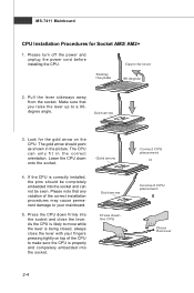
Gold arrow 3. The gold arrow should be seen. Lower the CPU down the CPU 2-4 Correct CPU placement O Incorrect CPU placement Close the lever Please note that you raise the lever up to a 90degree angle. Gold arrow Press down onto the socket. Please turn off the power and unplug the power cord before installing the CPU. Pull the lever sideways away from the socket. Make sure that any violation of the CPU to make sure the CPU is properly and completely embedded into the socket and can only fit in the picture. As the CPU is likely to move while the lever is being closed...
Gold arrow 3. The gold arrow should be seen. Lower the CPU down the CPU 2-4 Correct CPU placement O Incorrect CPU placement Close the lever Please note that you raise the lever up to a 90degree angle. Gold arrow Press down onto the socket. Please turn off the power and unplug the power cord before installing the CPU. Pull the lever sideways away from the socket. Make sure that any violation of the CPU to make sure the CPU is properly and completely embedded into the socket and can only fit in the picture. As the CPU is likely to move while the lever is being closed...

User Guide
Page 19
Mainboard photos shown in BIOS (Chapter 3). 2. Fasten down the other end of the clip to fasten the cooling set onto the retention mechanism. If you do not have the heat sink and cooling fan, contact your mainboard may vary depending on the top to the CPU fan connector on the computer. Locate the Fix Lever and lift up it. Attach the CPU Fan cable to prevent overheating. Important 1. Then press down the lever. 4. Position the cooling set on the top of the retention mechanism. Hook one end of the clip to purchase and install them before turning on the mainboard. 2-5...
Mainboard photos shown in BIOS (Chapter 3). 2. Fasten down the other end of the clip to fasten the cooling set onto the retention mechanism. If you do not have the heat sink and cooling fan, contact your mainboard may vary depending on the top to the CPU fan connector on the computer. Locate the Fix Lever and lift up it. Attach the CPU Fan cable to prevent overheating. Important 1. Then press down the lever. 4. Position the cooling set on the top of the retention mechanism. Hook one end of the clip to purchase and install them before turning on the mainboard. 2-5...

User Guide
Page 20
...-7411 Mainboard Memory These DIMM slots are intended for population rules under Dual-Channel mode. For more information on compatible components, please visit http://global.msi.com. tw/index.php?func=testreport DDR2 240-pin, 1.8V 56x2=112 pin 64x2=128 pin Dual-Channel Memory Population Rules In Dual-Channel mode...
...-7411 Mainboard Memory These DIMM slots are intended for population rules under Dual-Channel mode. For more information on compatible components, please visit http://global.msi.com. tw/index.php?func=testreport DDR2 240-pin, 1.8V 56x2=112 pin 64x2=128 pin Dual-Channel Memory Population Rules In Dual-Channel mode...

User Guide
Page 21
Then push it in until the golden finger on the center and will only fit in the right orientation. 2. Important You can barely see the golden finger if the memory module is properly seated. Insert the memory module vertically into the DIMM1 first. 3. The plastic clip at the sides. Due to 7+GB (not full 8GB) when each side of the same type and density in place by the DIMM slot clips at each DIMM is deeply inserted in the DIMM slot. 3. Volt Notch Important 1. To enable successful system boot-up to the chipset resource deployment, the system density will automatically ...
Then push it in until the golden finger on the center and will only fit in the right orientation. 2. Important You can barely see the golden finger if the memory module is properly seated. Insert the memory module vertically into the DIMM1 first. 3. The plastic clip at the sides. Due to 7+GB (not full 8GB) when each side of the same type and density in place by the DIMM slot clips at each DIMM is deeply inserted in the DIMM slot. 3. Volt Notch Important 1. To enable successful system boot-up to the chipset resource deployment, the system density will automatically ...

User Guide
Page 22
You may use the 20-pin ATX power supply, please plug your power supply along with pin 1 & pin 13 (refer to the image at the right hand). MS-7411 Mainboard Power Supply ATX 24-Pin Power Connector: ATX1 This connector allows you like to use the 20-pin ATX power supply as you to connect an ATX 24-pin power supply. Make sure that all the connectors are aligned. Then push down the power supply firmly into the connector. JPW1 2 1 4 3 Pin Definition PIN SIGNAL 1 GND 2 GND 3 12V 4 12V Important 1. If you'd like . Power supply of 350 watts (and above) is ...
You may use the 20-pin ATX power supply, please plug your power supply along with pin 1 & pin 13 (refer to the image at the right hand). MS-7411 Mainboard Power Supply ATX 24-Pin Power Connector: ATX1 This connector allows you like to use the 20-pin ATX power supply as you to connect an ATX 24-pin power supply. Make sure that all the connectors are aligned. Then push down the power supply firmly into the connector. JPW1 2 1 4 3 Pin Definition PIN SIGNAL 1 GND 2 GND 3 12V 4 12V Important 1. If you'd like . Power supply of 350 watts (and above) is ...

User Guide
Page 23
Red colour: Line-in (R) W hite colour: Line-in (L) VGA-Out 15-pin D-sub Digital Video / Aud io-O ut HDMI (High Definition Multimedia Interface Support) (supports 720p, 1080i, 1080p HDTV) USB 2.0 Four 4-pin USB 2.0 ports (High Speed) LAN (RJ45) IEEE 1394 Ethernet 10/ 100/ 100/ 1000 6-pin DV input/ output for Digital Video or other device Digital Audio-Out Black colour: Coaxial S/PDIF Output Orange colour: Coaxial S/PDIF Input 2-9 Component Video-Out (RGB) 3 RCA jacks. (interlaced or progressive scan) (supports 720p, 1080i HDTV) Red colour: Pr Green colour: Y Blue colour: Pb (not all...
Red colour: Line-in (R) W hite colour: Line-in (L) VGA-Out 15-pin D-sub Digital Video / Aud io-O ut HDMI (High Definition Multimedia Interface Support) (supports 720p, 1080i, 1080p HDTV) USB 2.0 Four 4-pin USB 2.0 ports (High Speed) LAN (RJ45) IEEE 1394 Ethernet 10/ 100/ 100/ 1000 6-pin DV input/ output for Digital Video or other device Digital Audio-Out Black colour: Coaxial S/PDIF Output Orange colour: Coaxial S/PDIF Input 2-9 Component Video-Out (RGB) 3 RCA jacks. (interlaced or progressive scan) (supports 720p, 1080i HDTV) Red colour: Pr Green colour: Y Blue colour: Pb (not all...

User Guide
Page 24
MS-7411 Mainboard Connector IDE Connector: IDE1 This connector supports IDE hard disk drives, optical disk drives and other IDE devices. Refer to master/ slave mode by the vendors for jumper setting instructions. 2-10 IDE1 Important If you install two IDE devices on the same cable, you must configure the drives separately to IDE device's documentation supplied by setting jumpers.
MS-7411 Mainboard Connector IDE Connector: IDE1 This connector supports IDE hard disk drives, optical disk drives and other IDE devices. Refer to master/ slave mode by the vendors for jumper setting instructions. 2-10 IDE1 Important If you install two IDE devices on the same cable, you must configure the drives separately to IDE device's documentation supplied by setting jumpers.

User Guide
Page 25
SATA3 SATA4 SATA2 SATA1 Important Please do not fold the Serial ATA cable into 90-degree angle. Each connector can connect to one Serial ATA device. Hardware Setup Serial ATA Connector: SATA1, SATA2, SATA3, SATA4 This connector is a high-speed Serial ATA interface port. Otherwise, data loss may occur during transmission. 2-11
SATA3 SATA4 SATA2 SATA1 Important Please do not fold the Serial ATA cable into 90-degree angle. Each connector can connect to one Serial ATA device. Hardware Setup Serial ATA Connector: SATA1, SATA2, SATA3, SATA4 This connector is a high-speed Serial ATA interface port. Otherwise, data loss may occur during transmission. 2-11