
User Guide
Page 3
...- fore connecting the equipment to moisture. Safety Instructions 1. ment from humidity. 4. Never pour any of the power source and adjust properly 110/220V be noted. 10. Liquid has penetrated into the opening that people can not get the equipment checked by the manufacturer. Replace only with the same or equivalent type...
...- fore connecting the equipment to moisture. Safety Instructions 1. ment from humidity. 4. Never pour any of the power source and adjust properly 110/220V be noted. 10. Liquid has penetrated into the opening that people can not get the equipment checked by the manufacturer. Replace only with the same or equivalent type...

User Guide
Page 8
... v Chapter 1 Getting Started 1-1 Mainboard Specifications 1-2 Mainboard Layout 1-4 Packing Checklist 1-5 Chapter 2 Hardware Setup 2-1 Quick Components Guide 2-2 CPU (Central Processing Unit 2-3 Memory...2-6 Power Supply 2-8 Back Panel...2-9 Connector...2-10 Jumper...2-16 Slot...2-17 Chapter 3 BIOS Setup 3-1 Entering Setup 3-2 The Menu Bar 3-4 Main...3-5 Advanced...3-6 Boot...3-18 Security...3-21 Chipset...3-22 Power...3-26 Exit...3-28 Appendix...
... v Chapter 1 Getting Started 1-1 Mainboard Specifications 1-2 Mainboard Layout 1-4 Packing Checklist 1-5 Chapter 2 Hardware Setup 2-1 Quick Components Guide 2-2 CPU (Central Processing Unit 2-3 Memory...2-6 Power Supply 2-8 Back Panel...2-9 Connector...2-10 Jumper...2-16 Slot...2-17 Chapter 3 BIOS Setup 3-1 Entering Setup 3-2 The Menu Bar 3-4 Main...3-5 Advanced...3-6 Boot...3-18 Security...3-21 Chipset...3-22 Power...3-26 Exit...3-28 Appendix...
User Guide
Page 10
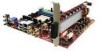
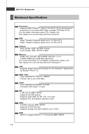
t w / i nde x . Supports Ultra DMA 33/ 66/ 100/ 133 mode - SATA1~4 support RAID 0/ 1/ 10 m ode by AMD® SB700 - Supports AMD® PhenomTM, AthlonTM 64/ 64 FX/ 64 X2 and SempronTM processors in the socket AM2/ AM2+ package (TDP ...
t w / i nde x . Supports Ultra DMA 33/ 66/ 100/ 133 mode - SATA1~4 support RAID 0/ 1/ 10 m ode by AMD® SB700 - Supports AMD® PhenomTM, AthlonTM 64/ 64 FX/ 64 X2 and SempronTM processors in the socket AM2/ AM2+ package (TDP ...

User Guide
Page 22
... 14 -12V 3 GND 15 GND 4 +5V 16 PS-ON# 5 GND 17 GND 6 +5V 18 GND 7 GND 19 GND 8 PW R OK 20 Res 9 5VSB 21 +5V 10 +12V 22 +5V 11 +12V 23 +5V 12 +3.3V 24 GND pin 13 pin 12 ATX 12V Power Connector: JPW1 This power connector is also...
... 14 -12V 3 GND 15 GND 4 +5V 16 PS-ON# 5 GND 17 GND 6 +5V 18 GND 7 GND 19 GND 8 PW R OK 20 Res 9 5VSB 21 +5V 10 +12V 22 +5V 11 +12V 23 +5V 12 +3.3V 24 GND pin 13 pin 12 ATX 12V Power Connector: JPW1 This power connector is also...

User Guide
Page 23
... io-O ut HDMI (High Definition Multimedia Interface Support) (supports 720p, 1080i, 1080p HDTV) USB 2.0 Four 4-pin USB 2.0 ports (High Speed) LAN (RJ45) IEEE 1394 Ethernet 10/ 100/ 100/ 1000 6-pin DV input/ output for Digital Video or other device Digital Audio-Out Black colour: Coaxial S/PDIF Output Orange colour: Coaxial S/PDIF...
... io-O ut HDMI (High Definition Multimedia Interface Support) (supports 720p, 1080i, 1080p HDTV) USB 2.0 Four 4-pin USB 2.0 ports (High Speed) LAN (RJ45) IEEE 1394 Ethernet 10/ 100/ 100/ 1000 6-pin DV input/ output for Digital Video or other device Digital Audio-Out Black colour: Coaxial S/PDIF Output Orange colour: Coaxial S/PDIF...

User Guide
Page 24
Refer to master/ slave mode by the vendors for jumper setting instructions. 2-10 MS-7411 Mainboard Connector IDE Connector: IDE1 This connector supports IDE hard disk drives, optical disk drives and other IDE devices. IDE1 Important If you install two IDE devices on the same cable, you must configure the drives separately to IDE device's documentation supplied by setting jumpers.
Refer to master/ slave mode by the vendors for jumper setting instructions. 2-10 MS-7411 Mainboard Connector IDE Connector: IDE1 This connector supports IDE hard disk drives, optical disk drives and other IDE devices. IDE1 Important If you install two IDE devices on the same cable, you must configure the drives separately to IDE device's documentation supplied by setting jumpers.

User Guide
Page 27
... microphone JACK1 Jack detection sense line from front panel JACK2 2-13 PIN SIGNAL 1 MIC_L 2 GND 3 MIC_R 4 PRESENCE# 5 LINE out_R 6 MIC_JD 7 Front_JD 8 NC 9 LINE out_L 10 LINEout_JD 2 10 1 9 JAUD1 Pin Definition DESCRIPTION Microphone - Left channel Jack detection return from the High Definition Audio CODEC jack detection resistor network No control Analog Port - Hardware...
... microphone JACK1 Jack detection sense line from front panel JACK2 2-13 PIN SIGNAL 1 MIC_L 2 GND 3 MIC_R 4 PRESENCE# 5 LINE out_R 6 MIC_JD 7 Front_JD 8 NC 9 LINE out_L 10 LINEout_JD 2 10 1 9 JAUD1 Pin Definition DESCRIPTION Microphone - Left channel Jack detection return from the High Definition Audio CODEC jack detection resistor network No control Analog Port - Hardware...

User Guide
Page 28
... USB interface peripherals such as USB HDD, digital cameras, MP3 players, printers, modems and the like. 2 10 1 9 JUSB0/ 1/ 2/ 3 Pin Definition PIN SIGNAL PIN SIGNAL 1 VCC 2 VCC 3 USB0- 4 USB1- 5 USB0+ 6 USB1+ 7 GND 8 GND 9 Key (no pin) 10 USB 2.0 Bracket (Optional) Important Note that the pins of VCC and GND must be connected correctly...
... USB interface peripherals such as USB HDD, digital cameras, MP3 players, printers, modems and the like. 2 10 1 9 JUSB0/ 1/ 2/ 3 Pin Definition PIN SIGNAL PIN SIGNAL 1 VCC 2 VCC 3 USB0- 4 USB1- 5 USB0+ 6 USB1+ 7 GND 8 GND 9 Key (no pin) 10 USB 2.0 Bracket (Optional) Important Note that the pins of VCC and GND must be connected correctly...

User Guide
Page 29
...PIN SIGNAL 1 TPA+ 2 TPA- 3 Ground 4 Ground 5 TPB+ 6 TPB- 7 Cable power 8 Cable power 9 Key (no pin) 10 Ground IEEE1394 Bracket (Optional) 2-15 Do not use. Hardware Setup Front Panel Connector: JFP1 This connector is compliant with Intel® Front Panel ...I/O Connectivity Design Guide. PIN Power Power LED Switch +- 1 2 JFP1 2 1 3 10 9 4 +HDD -+ Reset 5 6 LED Switch 7 8 9 SIGNAL HD_LED + FP PW R/SLP HD_LED FP PW R/SLP RST_SW PW R_SW + RST_SW + PW R_SW RSVD_DNU...
...PIN SIGNAL 1 TPA+ 2 TPA- 3 Ground 4 Ground 5 TPB+ 6 TPB- 7 Cable power 8 Cable power 9 Key (no pin) 10 Ground IEEE1394 Bracket (Optional) 2-15 Do not use. Hardware Setup Front Panel Connector: JFP1 This connector is compliant with Intel® Front Panel ...I/O Connectivity Design Guide. PIN Power Power LED Switch +- 1 2 JFP1 2 1 3 10 9 4 +HDD -+ Reset 5 6 LED Switch 7 8 9 SIGNAL HD_LED + FP PW R/SLP HD_LED FP PW R/SLP RST_SW PW R_SW + RST_SW + PW R_SW RSVD_DNU...

User Guide
Page 42
... hard disk failure. Block (Multi-Sector Transfer) W hen the setting is a utility that monitors your IDE hard drives can also support 32-bit transfer mode. 3-10 The settings are: [Auto], [Mode 0], [Mode 1], [Mode 2], [Mode 3], [Mode 4]. DMA Mode This item allows you to activate the S.M.A.R.T. (Self-Monitoring Analysis & Reporting Technology) capability for...
... hard disk failure. Block (Multi-Sector Transfer) W hen the setting is a utility that monitors your IDE hard drives can also support 32-bit transfer mode. 3-10 The settings are: [Auto], [Mode 0], [Mode 1], [Mode 2], [Mode 3], [Mode 4]. DMA Mode This item allows you to activate the S.M.A.R.T. (Self-Monitoring Analysis & Reporting Technology) capability for...

User Guide
Page 61
Appendix A Realtek ALC888 Audio The Realtek ALC888 provides 10-channel DAC that simultaneously supports 7.1 sound playback and 2 channels of independent stereo sound output (multiple streaming) through the Front-Out-Left and Front-OutRight channels.
Appendix A Realtek ALC888 Audio The Realtek ALC888 provides 10-channel DAC that simultaneously supports 7.1 sound playback and 2 channels of independent stereo sound output (multiple streaming) through the Front-Out-Left and Front-OutRight channels.

User Guide
Page 66
... from previous steps. Delete To delete the pre-saved settings which are saved permanently for future use Reset 10 bands of equalizer, ranging from 100Hz to use preload settings, simply click this tool. 10 bands of equalizer would go back to the default setting Enable / Disable To disable, you can temporarily stop...
... from previous steps. Delete To delete the pre-saved settings which are saved permanently for future use Reset 10 bands of equalizer, ranging from 100Hz to use preload settings, simply click this tool. 10 bands of equalizer would go back to the default setting Enable / Disable To disable, you can temporarily stop...

User Guide
Page 70
... to mute single or multiple volume controls or to let you can have music (stream 2 from back panel) in play. Realtek HD Audio Rear Output - A-10 Tool - MS-7411 Mainboard 3. Enable playback multi-streaming W ith this is to completely mute sound output.
... to mute single or multiple volume controls or to let you can have music (stream 2 from back panel) in play. Realtek HD Audio Rear Output - A-10 Tool - MS-7411 Mainboard 3. Enable playback multi-streaming W ith this is to completely mute sound output.

User Guide
Page 82
... screen, use the space key to choose a RAID mode (RAID 0/ 1/ 0+1) and use the arrow key to move to allow the greatest flexibility, manually. 1. RAID 1 or 10 only. B-4 MS-7411 Mainboard Define LD (Creating RAID) The selection of the RAID configuration should be created either automatically, or to the Drives Assignments window...
... screen, use the space key to choose a RAID mode (RAID 0/ 1/ 0+1) and use the arrow key to move to allow the greatest flexibility, manually. 1. RAID 1 or 10 only. B-4 MS-7411 Mainboard Define LD (Creating RAID) The selection of the RAID configuration should be created either automatically, or to the Drives Assignments window...

User Guide
Page 83
... configuration or press [Ctrl-Y] to choose the hard drives which you can create second LD with remaining capacity of the selected hard drives. 2. RAID 0 or 10 only. • Gigabyte Boundary, allows use the arrow key to allocate the RAID capacity manually.
... configuration or press [Ctrl-Y] to choose the hard drives which you can create second LD with remaining capacity of the selected hard drives. 2. RAID 0 or 10 only. • Gigabyte Boundary, allows use the arrow key to allocate the RAID capacity manually.

User Guide
Page 86
...Driver" button to install Vista click on the Setup screen. 3. W hen prompted, insert the floppy disk or media (Floppy, CD/DVD Or USB) and press Enter. 6. Leave the disk in the : for Windows XP ...installation, after the RAID volume is formatted, and W indows setup starts copying files. You should continue. 10. The next screen should confirm that contains the RAID driver,Press the "S" key to copy the files ...SBDrv\RAID\x86 and \ChipSet\ATI\Packages\Drivers\SBDrv\RAID\x64 to appear. B-8 Insert the MSI CD into the CD-ROM drive. 2. Insert the floppy that you complete the RAID BIOS...
...Driver" button to install Vista click on the Setup screen. 3. W hen prompted, insert the floppy disk or media (Floppy, CD/DVD Or USB) and press Enter. 6. Leave the disk in the : for Windows XP ...installation, after the RAID volume is formatted, and W indows setup starts copying files. You should continue. 10. The next screen should confirm that contains the RAID driver,Press the "S" key to copy the files ...SBDrv\RAID\x86 and \ChipSet\ATI\Packages\Drivers\SBDrv\RAID\x64 to appear. B-8 Insert the MSI CD into the CD-ROM drive. 2. Insert the floppy that you complete the RAID BIOS...