User Manual
Page 1
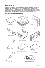
... have even link to install your phone or tablet. Quick Start Thank you for purchasing the MSI® MAG X570S TOMAHAWK MAX WIFI/ MAG X570S TORPEDO MAX motherboard. This Quick Start section provides demonstration diagrams about how to the URL by scanning the QR code. Preparing Tools and Components AMD® AM4 CPU CPU Fan DDR4 Memory Power Supply Unit Chassis Graphics Card Thermal Paste SATA Hard Disk Drive SATA DVD Drive Phillips Screwdriver A Package of the installations also provide video demonstrations. Some of...
... have even link to install your phone or tablet. Quick Start Thank you for purchasing the MSI® MAG X570S TOMAHAWK MAX WIFI/ MAG X570S TORPEDO MAX motherboard. This Quick Start section provides demonstration diagrams about how to the URL by scanning the QR code. Preparing Tools and Components AMD® AM4 CPU CPU Fan DDR4 Memory Power Supply Unit Chassis Graphics Card Thermal Paste SATA Hard Disk Drive SATA DVD Drive Phillips Screwdriver A Package of the installations also provide video demonstrations. Some of...
User Manual
Page 12
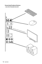
Connecting Peripheral Devices ∙∙ MAG X570S TOMAHAWK MAX WIFI Processor with integrated graphics 12 Quick Start
Connecting Peripheral Devices ∙∙ MAG X570S TOMAHAWK MAX WIFI Processor with integrated graphics 12 Quick Start
User Manual
Page 15
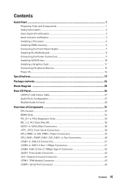
... Information 2 Case stand-off notification 3 Avoid collision notification 3 Installing a Processor 4 Installing DDR4 memory 6 Connecting the Front Panel Header 7 Installing the Motherboard 8 Connecting the Power Connectors 9 Installing SATA Drives 10 Installing a Graphics Card 11 Connecting Peripheral Devices 12 Power On...14 Specifications...17 Package contents 24 Block Diagram ...25 Rear I/O Panel...26 LAN Port LED Status Table 27 Audio Ports Configuration 27 Realtek Audio Console 28 Overview of Components 31 CPU Socket ...33 DIMM Slots...34 PCI_E1~4: PCIe Expansion Slots 35...
... Information 2 Case stand-off notification 3 Avoid collision notification 3 Installing a Processor 4 Installing DDR4 memory 6 Connecting the Front Panel Header 7 Installing the Motherboard 8 Connecting the Power Connectors 9 Installing SATA Drives 10 Installing a Graphics Card 11 Connecting Peripheral Devices 12 Power On...14 Specifications...17 Package contents 24 Block Diagram ...25 Rear I/O Panel...26 LAN Port LED Status Table 27 Audio Ports Configuration 27 Realtek Audio Console 28 Overview of Components 31 CPU Socket ...33 DIMM Slots...34 PCI_E1~4: PCIe Expansion Slots 35...

User Manual
Page 16
JBAT1: Clear CMOS (Reset BIOS) Jumper 44 JPWRLED1: LED power input 45 EZ Debug LED...45 JRGB1~2: RGB LED connectors 46 JRAINBOW1~2: Addressable RGB LED connectors 47 Installing OS, Drivers & MSI Center 48 Installing Windows® 10 48 Installing Drivers 48 MSI Center ...48 UEFI BIOS...49 BIOS Setup ...50 Entering BIOS Setup 50 BIOS User Guide 50 Resetting BIOS...51 Updating BIOS...51 RAID Configuration 53 Troubleshooting 54 16 Contents
JBAT1: Clear CMOS (Reset BIOS) Jumper 44 JPWRLED1: LED power input 45 EZ Debug LED...45 JRGB1~2: RGB LED connectors 46 JRAINBOW1~2: Addressable RGB LED connectors 47 Installing OS, Drivers & MSI Center 48 Installing Windows® 10 48 Installing Drivers 48 MSI Center ...48 UEFI BIOS...49 BIOS Setup ...50 Entering BIOS Setup 50 BIOS User Guide 50 Resetting BIOS...51 Updating BIOS...51 RAID Configuration 53 Troubleshooting 54 16 Contents
User Manual
Page 18
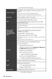
...Series desktop processors ▪▪Supports up to SATA 6Gb/s ▪▪M2_1 slot (from Processor) ▫▫Support 2280/22110 storage devices ▪▪M2_2 slot (from AMD X570 Chipset) ▫▫ Supports 2242/ 2260/ 2280 storage devices ∙∙Supports RAID 0, RAID 1 and RAID 10 ∙∙Realtek® ALC4080 Codec ▪▪7.1-Channel High Definition Audio ▪▪Supports S/PDIF output NUVOTON NCT6797D Controller Chip Continued on the CPU installed. Onboard Graphics Multi-GPU LAN Wireless LAN & Bluetooth® (For MAG X570S TOMAHAWK MAX WIFI...
...Series desktop processors ▪▪Supports up to SATA 6Gb/s ▪▪M2_1 slot (from Processor) ▫▫Support 2280/22110 storage devices ▪▪M2_2 slot (from AMD X570 Chipset) ▫▫ Supports 2242/ 2260/ 2280 storage devices ∙∙Supports RAID 0, RAID 1 and RAID 10 ∙∙Realtek® ALC4080 Codec ▪▪7.1-Channel High Definition Audio ▪▪Supports S/PDIF output NUVOTON NCT6797D Controller Chip Continued on the CPU installed. Onboard Graphics Multi-GPU LAN Wireless LAN & Bluetooth® (For MAG X570S TOMAHAWK MAX WIFI...
User Manual
Page 19
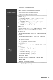
... panel USB 2.0 Hub ∙∙5x USB 2.0 ports (1 Type-A port on the back panel, 4 ports available through the internal USB 2.0 connectors) AMD Processor ∙∙2x USB 3.2 Gen 2 10Gbps ports on the back panel (Type-A &Type-C) ∙∙2x USB 3.2 Gen 1 5Gbps Type-A ports on the back panel ∙∙1x Flash BIOS Button ∙∙1x PS/2 keyboard/ mouse combo port ∙∙2x USB 2.0 ports ∙∙2x Wi-Fi Antenna connectors (For MAG X570S TOMAHAWK MAX WIFI) ∙∙2x USB 3.2 Gen1 5Gbps Type-A ports...
... panel USB 2.0 Hub ∙∙5x USB 2.0 ports (1 Type-A port on the back panel, 4 ports available through the internal USB 2.0 connectors) AMD Processor ∙∙2x USB 3.2 Gen 2 10Gbps ports on the back panel (Type-A &Type-C) ∙∙2x USB 3.2 Gen 1 5Gbps Type-A ports on the back panel ∙∙1x Flash BIOS Button ∙∙1x PS/2 keyboard/ mouse combo port ∙∙2x USB 2.0 ports ∙∙2x Wi-Fi Antenna connectors (For MAG X570S TOMAHAWK MAX WIFI) ∙∙2x USB 3.2 Gen1 5Gbps Type-A ports...

User Manual
Page 20
... USB 3.2 Gen 2 10Gbps Type-C port ∙∙1x 4-pin CPU fan connector ∙∙1x 4-pin water-pump connector ∙∙4x 4-pin system fan connectors ∙∙1x Front panel audio connector ∙∙2x System panel connectors ∙∙1x Chassis Intrusion connector ∙∙1x TPM module connector ∙∙1x Serial port connector ∙∙1x Chassis Intrusion connector Jumpers ∙∙1x Clear CMOS jumper LED Features ∙∙2x 4-pin RGB LED connectors ∙∙2x 3-pin RAINBOW LED connectors...
... USB 3.2 Gen 2 10Gbps Type-C port ∙∙1x 4-pin CPU fan connector ∙∙1x 4-pin water-pump connector ∙∙4x 4-pin system fan connectors ∙∙1x Front panel audio connector ∙∙2x System panel connectors ∙∙1x Chassis Intrusion connector ∙∙1x TPM module connector ∙∙1x Serial port connector ∙∙1x Chassis Intrusion connector Jumpers ∙∙1x Clear CMOS jumper LED Features ∙∙2x 4-pin RGB LED connectors ∙∙2x 3-pin RAINBOW LED connectors...
User Manual
Page 21
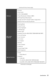
... Cooling ∙∙User Scenario ∙∙True Color ∙∙Live Update ∙∙ Monitor ∙∙Super Charger ∙∙Speed Up ∙∙Smart Image Finder ∙∙MSI Companion ∙∙ Audio ▪▪Audio Boost 5 ∙∙ Network ▪▪2.5G LAN ▪▪1G LAN (For MAG X570S TORPEDO MAX) ▪▪Intel WiFi 6E (For MAG X570S TOMAHAWK MAX WIFI) Continued on next...
... Cooling ∙∙User Scenario ∙∙True Color ∙∙Live Update ∙∙ Monitor ∙∙Super Charger ∙∙Speed Up ∙∙Smart Image Finder ∙∙MSI Companion ∙∙ Audio ▪▪Audio Boost 5 ∙∙ Network ▪▪2.5G LAN ▪▪1G LAN (For MAG X570S TORPEDO MAX) ▪▪Intel WiFi 6E (For MAG X570S TOMAHAWK MAX WIFI) Continued on next...
User Manual
Page 22
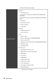
... (For MAG X570S TOMAHAWK MAX WIFI) ▪▪EZ LED Control ▪▪EZ DEBUG LED ∙∙ Performance ▪▪Lightning Gen 4 PCI-E Slot ▪▪Multi GPU-CrossFire Technology ▪▪DDR4 Boost ▪▪Core Boost ▪▪GAME Boost ▪▪USB with type A+C ▪▪USB 3.2 Gen 2 10G ▪▪Front USB Type-C ▪▪2oz Copper thickened PCB ▪▪Dual CPU Power Continued...
... (For MAG X570S TOMAHAWK MAX WIFI) ▪▪EZ LED Control ▪▪EZ DEBUG LED ∙∙ Performance ▪▪Lightning Gen 4 PCI-E Slot ▪▪Multi GPU-CrossFire Technology ▪▪DDR4 Boost ▪▪Core Boost ▪▪GAME Boost ▪▪USB with type A+C ▪▪USB 3.2 Gen 2 10G ▪▪Front USB Type-C ▪▪2oz Copper thickened PCB ▪▪Dual CPU Power Continued...
User Manual
Page 24
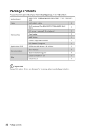
...contents of the above items are damaged or missing, please contact your motherboard package. It should contain: Motherboard MAG X570S TOMAHAWK MAX WIFI/ MAG X570S TORPEDO MAX Cable SATA 6Gb/s cable 2 Wi-Fi antenna (For MAG X570S TOMAHAWK MAX WIFI) 1 M.2 screw + standoff (2 sets/pack) 1 Accessories Case badge 1 MAG Sticker 1 Product registration card 1 MSI Reward Program 1 Application DVD USB drive with drivers & utilities 1 User manual 1 Documentation Quick installation guide 1 Small screwdriver set 1 Gifts Small brush 1 ⚠⚠Important If any of your...
...contents of the above items are damaged or missing, please contact your motherboard package. It should contain: Motherboard MAG X570S TOMAHAWK MAX WIFI/ MAG X570S TORPEDO MAX Cable SATA 6Gb/s cable 2 Wi-Fi antenna (For MAG X570S TOMAHAWK MAX WIFI) 1 M.2 screw + standoff (2 sets/pack) 1 Accessories Case badge 1 MAG Sticker 1 Product registration card 1 MSI Reward Program 1 Application DVD USB drive with drivers & utilities 1 User manual 1 Documentation Quick installation guide 1 Small screwdriver set 1 Gifts Small brush 1 ⚠⚠Important If any of your...
User Manual
Page 26
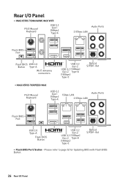
...page 52 for Updating BIOS with Flash BIOS Button. 26 Rear I /O Panel ∙∙ MAG X570S TOMAHAWK MAX WIFI PS/2 Mouse/ Keyboard USB 3.2 Gen1 (5Gbps) Type-A 2.5Gbps LAN Audio Ports Flash BIOS Port Flash BIOS USB 2.0 Button Type-A Wi-Fi Antenna connectors USB 3.2 Gen 2 USB 3.2 (10Gbps) Gen 2 Type-A (10Gbps) Type-C Optical S/PDIF-Out ∙∙ MAG X570S TORPEDO MAX PS/2 Mouse/ Keyboard USB 3.2 Gen1 (5Gbps) Type-A 1Gbps LAN 2.5Gbps LAN Audio Ports Flash BIOS Port USB 2.0 Type-A Flash BIOS Button USB 3.2 Gen 2 USB 3.2 (10Gbps) Gen 2 Type-A (10Gbps) Type-C Optical S/PDIF...
...page 52 for Updating BIOS with Flash BIOS Button. 26 Rear I /O Panel ∙∙ MAG X570S TOMAHAWK MAX WIFI PS/2 Mouse/ Keyboard USB 3.2 Gen1 (5Gbps) Type-A 2.5Gbps LAN Audio Ports Flash BIOS Port Flash BIOS USB 2.0 Button Type-A Wi-Fi Antenna connectors USB 3.2 Gen 2 USB 3.2 (10Gbps) Gen 2 Type-A (10Gbps) Type-C Optical S/PDIF-Out ∙∙ MAG X570S TORPEDO MAX PS/2 Mouse/ Keyboard USB 3.2 Gen1 (5Gbps) Type-A 1Gbps LAN 2.5Gbps LAN Audio Ports Flash BIOS Port USB 2.0 Type-A Flash BIOS Button USB 3.2 Gen 2 USB 3.2 (10Gbps) Gen 2 Type-A (10Gbps) Type-C Optical S/PDIF...

User Manual
Page 44
... the motherboard to clear the CMOS memory. Power off the computer and unplug the power cord 2. Use a jumper cap to default values 1. Keep Data (default) Clear CMOS/ Reset BIOS Resetting BIOS to short JBAT1 for about 5-10 seconds. 3. If you to connect the optional serial port with bracket. 2 10 1 9 1 DCD 2 SIN 3 SOUT 4 DTR 5 Ground 6 DSR 7 RTS 8 CTS 9 RI 10 No Pin JBAT1: Clear CMOS (Reset BIOS) Jumper There is CMOS memory onboard that is external powered from JBAT1. 4. Remove the jumper cap from a battery located...
... the motherboard to clear the CMOS memory. Power off the computer and unplug the power cord 2. Use a jumper cap to default values 1. Keep Data (default) Clear CMOS/ Reset BIOS Resetting BIOS to short JBAT1 for about 5-10 seconds. 3. If you to connect the optional serial port with bracket. 2 10 1 9 1 DCD 2 SIN 3 SOUT 4 DTR 5 Ground 6 DSR 7 RTS 8 CTS 9 RI 10 No Pin JBAT1: Clear CMOS (Reset BIOS) Jumper There is CMOS memory onboard that is external powered from JBAT1. 4. Remove the jumper cap from a battery located...
User Manual
Page 47
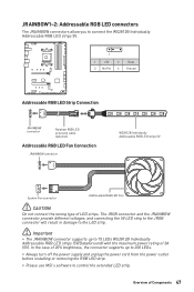
...;Always turn off the power supply and unplug the power cord from the power outlet before installing or removing the RGB LED strip. ∙∙Please use MSI's software to 75 LEDs WS2812B Individually Addressable RGB LED strips (5V/Data/Ground) with the maximum power rating of 20% brightness, the connector supports up to control the extended LED strip. JRAINBOW1~2: Addressable RGB LED connectors The JRAINBOW connectors allow you to connect the...
...;Always turn off the power supply and unplug the power cord from the power outlet before installing or removing the RGB LED strip. ∙∙Please use MSI's software to 75 LEDs WS2812B Individually Addressable RGB LED strips (5V/Data/Ground) with the maximum power rating of 20% brightness, the connector supports up to control the extended LED strip. JRAINBOW1~2: Addressable RGB LED connectors The JRAINBOW connectors allow you to connect the...
User Manual
Page 48
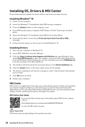
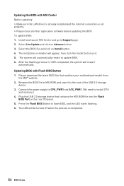
... screen to finish. 8. Press F11 key during the computer POST (Power-On Self Test) to control and synchronize LED light effects on PCs and other MSI products. Follow the instructions on the product you to restart. 7. The installer will prompt you have. 48 Installing OS, Drivers & MSI Center Select the Windows® 10 installation disc/USB from the Windows Control Panel, you easily optimize game settings and smoothly use content creation softwares. Start...
... screen to finish. 8. Press F11 key during the computer POST (Power-On Self Test) to control and synchronize LED light effects on PCs and other MSI products. Follow the instructions on the product you to restart. 7. The installer will prompt you have. 48 Installing OS, Drivers & MSI Center Select the Windows® 10 installation disc/USB from the Windows Control Panel, you easily optimize game settings and smoothly use content creation softwares. Start...
User Manual
Page 50
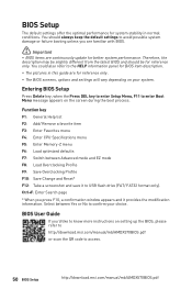
...://download.msi.com/manual/mb/AMDX570BIOS.pdf or scan the QR code to USB flash drive (FAT/ FAT32 format only). Select between Advanced mode and EZ mode F8: Load Overclocking Profile F9: Save Overclocking Profile F10: Save Change and Reset* F12: Take a screenshot and save it provides the modification information. Therefore, the description may be slightly different from the latest BIOS and should always keep the default settings...
...://download.msi.com/manual/mb/AMDX570BIOS.pdf or scan the QR code to USB flash drive (FAT/ FAT32 format only). Select between Advanced mode and EZ mode F8: Load Overclocking Profile F9: Save Overclocking Profile F10: Save Change and Reset* F12: Take a screenshot and save it provides the modification information. Therefore, the description may be slightly different from the latest BIOS and should always keep the default settings...
User Manual
Page 51
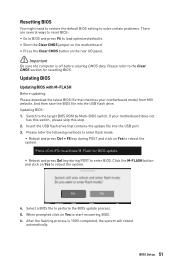
... before clearing CMOS data. Resetting BIOS You might need to restore the default BIOS setting to solve certain problems. There are several ways to reset BIOS: ∙∙Go to BIOS and press F6 to load optimized defaults. ∙∙Short the Clear CMOS jumper on the motherboard. ∙∙Press the Clear CMOS button on Yes to start recovering BIOS. 6. And then save the BIOS file into the USB port. 3. Switch to enter BIOS. BIOS Setup 51 If your motherboard model from MSI website...
... before clearing CMOS data. Resetting BIOS You might need to restore the default BIOS setting to solve certain problems. There are several ways to reset BIOS: ∙∙Go to BIOS and press F6 to load optimized defaults. ∙∙Short the Clear CMOS jumper on the motherboard. ∙∙Press the Clear CMOS button on Yes to start recovering BIOS. 6. And then save the BIOS file into the USB port. 3. Switch to enter BIOS. BIOS Setup 51 If your motherboard model from MSI website...
User Manual
Page 52
Connect the power supply to CPU_PWR1 and ATX_PWR1. (No need to flash BIOS, and the LED starts flashing. 6. Select the BIOS file and click on the rear I/O panel. 5. Rename the BIOS file to the root of the USB 2.0 storage device. 3. Updating the BIOS with Flash BIOS Button 1. The system will be turned off when the process is completed. 52 BIOS Setup Updating BIOS with MSI Center Before updating: ∙∙Make sure the LAN driver is already installed and the internet connection is...
Connect the power supply to CPU_PWR1 and ATX_PWR1. (No need to flash BIOS, and the LED starts flashing. 6. Select the BIOS file and click on the rear I/O panel. 5. Rename the BIOS file to the root of the USB 2.0 storage device. 3. Updating the BIOS with Flash BIOS Button 1. The system will be turned off when the process is completed. 52 BIOS Setup Updating BIOS with MSI Center Before updating: ∙∙Make sure the LAN driver is already installed and the internet connection is...

User Manual
Page 54
... LAN port LEDs are connected from the power supply to the motherboard? ∙∙Some power supply units have a power button on the rear side, make sure the button is turned on. ∙∙Check if the power switch cable is connected to JFP1 pin header properly. ∙∙Verify the Clear CMOS jumper JBAT1 is on the motherboard rear IO panel. ∙∙Remove secondary speakers/ headphones, HDMI cables, USB audio devices. ∙∙Test with Dual BIOS) 54 Troubleshooting The power is set to audio ports...
... LAN port LEDs are connected from the power supply to the motherboard? ∙∙Some power supply units have a power button on the rear side, make sure the button is turned on. ∙∙Check if the power switch cable is connected to JFP1 pin header properly. ∙∙Verify the Clear CMOS jumper JBAT1 is on the motherboard rear IO panel. ∙∙Remove secondary speakers/ headphones, HDMI cables, USB audio devices. ∙∙Test with Dual BIOS) 54 Troubleshooting The power is set to audio ports...
User Manual
Page 55
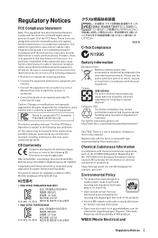
... button cell battery may be disposed of the following two conditions: (1) This device may cause harmful interference to radio communications. CE Conformity Products bearing the CE marking comply with one or more of the following EU Directives as unsorted household waste. Low Voltage Directive 2014/35/EU; KC인증서 •• MAG X570S TOMAHAWK MAX WIFI 10...
... button cell battery may be disposed of the following two conditions: (1) This device may cause harmful interference to radio communications. CE Conformity Products bearing the CE marking comply with one or more of the following EU Directives as unsorted household waste. Low Voltage Directive 2014/35/EU; KC인증서 •• MAG X570S TOMAHAWK MAX WIFI 10...
User Manual
Page 58
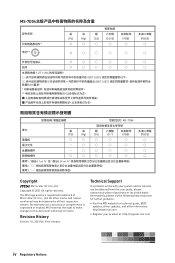
... •• Visit the MSI website for technical guide, BIOS updates, driver updates, and other marks and names mentioned may be obtained from the user guide, please contact your place of purchase or local distributor. All other information: http://www.msi.com •• Register your...., Ltd. No warranty as to this document without prior notice. Technical Support If a problem arises with your product at: http://register.msi.com iv Regulatory Notices The MSI logo used is expressed or implied. Revision History Version 1.0, 2021/06, First release. "超出0.1 wt 0.01 wt...
... •• Visit the MSI website for technical guide, BIOS updates, driver updates, and other marks and names mentioned may be obtained from the user guide, please contact your place of purchase or local distributor. All other information: http://www.msi.com •• Register your...., Ltd. No warranty as to this document without prior notice. Technical Support If a problem arises with your product at: http://register.msi.com iv Regulatory Notices The MSI logo used is expressed or implied. Revision History Version 1.0, 2021/06, First release. "超出0.1 wt 0.01 wt...


