

User Guide
Page 2
... DualNet, and nForce are registered trademarks of AMD Corporation. Alternatively, please try the following help resources for FAQ, technical guide, BIOS updates, driver updates, and other countries. Trademarks All trademarks are registered trademarks of Intel Corporation. Award® is a registered ... intellectual property of M ICRO-STAR INTERNATIONAL. PS/2 and OS®/2 are registered trademarks of Microsoft Corporation. Visit the MSI website for further guidance. Copyright Notice The material in this document, but no solution can be obtained from the user's...
... DualNet, and nForce are registered trademarks of AMD Corporation. Alternatively, please try the following help resources for FAQ, technical guide, BIOS updates, driver updates, and other countries. Trademarks All trademarks are registered trademarks of Intel Corporation. Award® is a registered ... intellectual property of M ICRO-STAR INTERNATIONAL. PS/2 and OS®/2 are registered trademarks of Microsoft Corporation. Visit the MSI website for further guidance. Copyright Notice The material in this document, but no solution can be obtained from the user's...
User Guide
Page 9
Slots ...2-19 PCI (Peripheral Component Interconnect) Express Slots 2-19 PCI Interrupt Request Routing 2-20 Chapter 3 BIOS Setup 3-1 Entering Setup ...3-2 Control Keys 3-3 Getting Help 3-3 General Help
Slots ...2-19 PCI (Peripheral Component Interconnect) Express Slots 2-19 PCI Interrupt Request Routing 2-20 Chapter 3 BIOS Setup 3-1 Entering Setup ...3-2 Control Keys 3-3 Getting Help 3-3 General Help
User Guide
Page 14
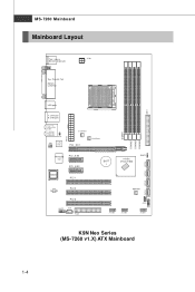
Ou t B: RS-Out JCI1 JIR1 LAN Chip ATX 2 SYSFAN 1 PCI _EX1 CPUFAN1 DIMM1 DIMM2 DIMM3 DIMM4 S ATA 1 SATA2 SATA3 SATA4 W inbond I n M :Li n e- O u t B: Mic T:SS-Out M :C S- MS-7260 Mainboard Mainboard Layout Top : mouse Bottom: keyboard Top : Parallel Port B ot to m: COM Port JPW1 USB ports IDE1 T: LAN jack B: USB ports T:Line-I / O PCI _E X2 PCI _EX3 BIOS PCI 1 B AT T + nvidia nForce 550 J BAT 1 ALC883 PCI 2 PCI 3 JAUD1 JCD1 FDD1 NB FA N1 JUS B3 JUS B2 JFP2 JFP 1 JUSB1 K9N Neo Series (MS-7260 v1.X) ATX Mainboard 1-4
Ou t B: RS-Out JCI1 JIR1 LAN Chip ATX 2 SYSFAN 1 PCI _EX1 CPUFAN1 DIMM1 DIMM2 DIMM3 DIMM4 S ATA 1 SATA2 SATA3 SATA4 W inbond I n M :Li n e- O u t B: Mic T:SS-Out M :C S- MS-7260 Mainboard Mainboard Layout Top : mouse Bottom: keyboard Top : Parallel Port B ot to m: COM Port JPW1 USB ports IDE1 T: LAN jack B: USB ports T:Line-I / O PCI _E X2 PCI _EX3 BIOS PCI 1 B AT T + nvidia nForce 550 J BAT 1 ALC883 PCI 2 PCI 3 JAUD1 JCD1 FDD1 NB FA N1 JUS B3 JUS B2 JFP2 JFP 1 JUSB1 K9N Neo Series (MS-7260 v1.X) ATX Mainboard 1-4
User Guide
Page 17
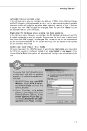
... click "Save" to save the desired FSB you may adjust the CPU fan speed. Center-side: Cool'n'Quiet / User mode Here you just configured. Run BIOS Setup, and select H/W Monitor. If you choose User mode, you may use the "+" and "-" buttons to adjust, then click "OK" to apply the changes. E nt...
... click "Save" to save the desired FSB you may adjust the CPU fan speed. Center-side: Cool'n'Quiet / User mode Here you just configured. Run BIOS Setup, and select H/W Monitor. If you choose User mode, you may use the "+" and "-" buttons to adjust, then click "OK" to apply the changes. E nt...
User Guide
Page 31
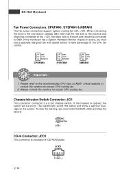
... advantage of the CPU fan c on the screen. Always consult the vendors for proper CPU cooling fan. 2. To clear the warning, you must enter the BIOS utility and clear the record. 2 GND 1 CINTRU JCI1 CD-In Connector: JCD1 This connector is provided for CD-ROM audio. If the chassis is Ground...
... advantage of the CPU fan c on the screen. Always consult the vendors for proper CPU cooling fan. 2. To clear the warning, you must enter the BIOS utility and clear the record. 2 GND 1 CINTRU JCI1 CD-In Connector: JCD1 This connector is provided for CD-ROM audio. If the chassis is Ground...
User Guide
Page 32
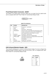
... Connector: JAUD1 The JAUD1 front panel audio connector allows you to connect to IrDA Infrared module. Left channel 2 GND Ground 3 PORT 1R Analog Port 1 - signals BIOS that a High Definition Audio dongle is compliant with Intel® Front Panel I /O Connectivity Design Guide. 2 1 10 9 JAUD1 JAUD1 Pin Definition PIN SIGNAL DESCRIPTION 1 PORT 1L...
... Connector: JAUD1 The JAUD1 front panel audio connector allows you to connect to IrDA Infrared module. Left channel 2 GND Ground 3 PORT 1R Analog Port 1 - signals BIOS that a High Definition Audio dongle is compliant with Intel® Front Panel I /O Connectivity Design Guide. 2 1 10 9 JAUD1 JAUD1 Pin Definition PIN SIGNAL DESCRIPTION 1 PORT 1L...
User Guide
Page 36
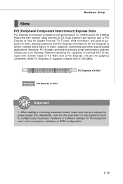
... graphics controllers, while PCI Express x1 supports transfer rate of 4.0 GB/s over a PCI Express x1 lane for the expansion card, such as jumpers, switches or BIOS configuration. 2-19 Hardware Setup Slots PCI (Peripheral Component Interconnect) Express Slots PCI Express architecture provides a high performance I /O. Moreover, PCI Express architecture provides a high performance graphics...
... graphics controllers, while PCI Express x1 supports transfer rate of 4.0 GB/s over a PCI Express x1 lane for the expansion card, such as jumpers, switches or BIOS configuration. 2-19 Hardware Setup Slots PCI (Peripheral Component Interconnect) Express Slots PCI Express architecture provides a high performance I /O. Moreover, PCI Express architecture provides a high performance graphics...
User Guide
Page 38
You may need to run the Setup program when: ² An error message appears on the BIOS Setup program and allows you to run SETUP. ² You want to configure the system for customized features. 3-1 Chapter 3 BIOS Setup BIOS Setup This chapter provides information on the screen during the system booting up, and requests you to change the default settings for optimum use.
You may need to run the Setup program when: ² An error message appears on the BIOS Setup program and allows you to run SETUP. ² You want to configure the system for customized features. 3-1 Chapter 3 BIOS Setup BIOS Setup This chapter provides information on the screen during the system booting up, and requests you to change the default settings for optimum use.
User Guide
Page 39
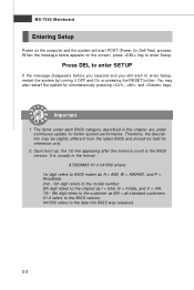
... On or pressing the RESET button. Important 1. Upon boot-up, the 1st line appearing after the memory count is usually in this BIOS was released. 3-2 V1.0 refers to the BIOS version. 041506 refers to the customer as I = Intel, N = nVidia, and V = VIA. 7th - 8th digit refers to the date this ... below appears on the computer and the system will start POST (Power On Self Test) process. You may be slightly different from the latest BIOS and should be held for better system performance. MS-7260 Mainboard Entering Setup Power on the screen, press key to enter Setup, restart the...
... On or pressing the RESET button. Important 1. Upon boot-up, the 1st line appearing after the memory count is usually in this BIOS was released. 3-2 V1.0 refers to the BIOS version. 041506 refers to the customer as I = Intel, N = nVidia, and V = VIA. 7th - 8th digit refers to the date this ... below appears on the computer and the system will start POST (Power On Self Test) process. You may be slightly different from the latest BIOS and should be held for better system performance. MS-7260 Mainboard Entering Setup Power on the screen, press key to enter Setup, restart the...
User Guide
Page 40
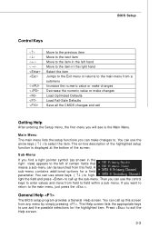
... and the possible selections for a field parameter. The Help screen lists the appropriate keys to use the arrow keys ( ↑↓ ) to select the item. BIOS Setup Control Keys Enter> Move to the previous item Move to the next item Move to the item in the left hand Move to the... call up this field. You can use the control keys to enter values and move from field to field within a sub-menu. General Help The BIOS setup program provides a General Help screen. Main Menu The main menu lists the setup functions you will see is displayed at the bottom of the...
... and the possible selections for a field parameter. The Help screen lists the appropriate keys to use the arrow keys ( ↑↓ ) to select the item. BIOS Setup Control Keys Enter> Move to the previous item Move to the next item Move to the item in the left hand Move to the... call up this field. You can use the control keys to enter values and move from field to field within a sub-menu. General Help The BIOS setup program provides a General Help screen. Main Menu The main menu lists the setup functions you will see is displayed at the bottom of the...
User Guide
Page 41
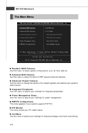
... the values in the chipset registers and optimize your settings for power management. PNP/PCI Configurations This entry appears if your PC health status. Advanced BIOS Features Use this menu to specify your system's performance.
... the values in the chipset registers and optimize your settings for power management. PNP/PCI Configurations This entry appears if your PC health status. Advanced BIOS Features Use this menu to specify your system's performance.
User Guide
Page 42
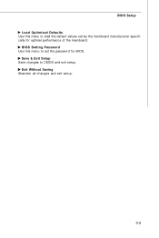
Exit Without Saving Abandon all changes and exit setup. 3-5 Save & Exit Setup Save changes to CMOS and exit setup. BIOS Setting Password Use this menu to load the default values set the password for optimal performance of the mainboard. BIOS Setup Load Optimized Defaults Use this menu to set by the mainboard manufacturer specifically for BIOS.
Exit Without Saving Abandon all changes and exit setup. 3-5 Save & Exit Setup Save changes to CMOS and exit setup. BIOS Setting Password Use this menu to load the default values set the password for optimal performance of the mainboard. BIOS Setup Load Optimized Defaults Use this menu to set by the mainboard manufacturer specifically for BIOS.

User Guide
Page 43
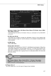
date The date from 1 to Sat, determined by BIOS. IDE Primary M aster/ Slave, Serial-ATA 0/1 Primary/ Secondary Channel Press to select the value you want in Standard CMOS Features Menu includes some basic setup ...
date The date from 1 to Sat, determined by BIOS. IDE Primary M aster/ Slave, Serial-ATA 0/1 Primary/ Secondary Channel Press to select the value you want in Standard CMOS Features Menu includes some basic setup ...
User Guide
Page 44
S.M.A.R.T is going to fail to the IDE/SATA connector. BIOS Setup Device/ Vender/ Size/ LBA Mode/ Block M ode/ PIO Mode/ Async DM A/ Ultra DMA/ S.M.A.R.T. This gives you connected to a safe place before the hard disk ...
S.M.A.R.T is going to fail to the IDE/SATA connector. BIOS Setup Device/ Vender/ Size/ LBA Mode/ Block M ode/ PIO Mode/ Async DM A/ Ultra DMA/ S.M.A.R.T. This gives you connected to a safe place before the hard disk ...
User Guide
Page 45
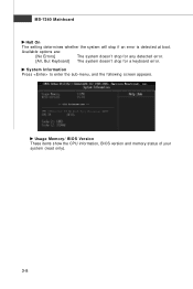
Usage Memory/ BIOS Version These items show the CPU information, BIOS version and memory status of your system (read only). 3-8 Available options are: [No Errors] The system doesn't stop for a keyboard error. System Information Press to enter the sub-menu, and the following screen appears. MS-7260 Mainboard Halt On The setting determines whether the system will stop for any detected error. [All, But Keyboard] The system doesn't stop if an error is detected at boot.
Usage Memory/ BIOS Version These items show the CPU information, BIOS version and memory status of your system (read only). 3-8 Available options are: [No Errors] The system doesn't stop for a keyboard error. System Information Press to enter the sub-menu, and the following screen appears. MS-7260 Mainboard Halt On The setting determines whether the system will stop for any detected error. [All, But Keyboard] The system doesn't stop if an error is detected at boot.
User Guide
Page 46
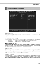
... APIC mode will skip some check items. Full Screen LOGO Display This item enables you to show the company logo on the numeric keypad. Advanced BIOS Features BIOS Setup Quick Booting Setting the item to [Enabled] allows the system to boot within 5 seconds since it is possible if you choose [Yes]. Settings...
... APIC mode will skip some check items. Full Screen LOGO Display This item enables you to show the company logo on the numeric keypad. Advanced BIOS Features BIOS Setup Quick Booting Setting the item to [Enabled] allows the system to boot within 5 seconds since it is possible if you choose [Yes]. Settings...
User Guide
Page 47
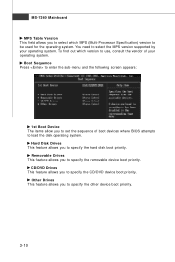
MS-7260 Mainboard MPS Table Version This field allows you to select which version to use, consult the vendor of boot devices where BIOS attempts to set the sequence of your operating system. Removable Drives This feature allows you to be used for the operating system. Hard Disk Drives ...
MS-7260 Mainboard MPS Table Version This field allows you to select which version to use, consult the vendor of boot devices where BIOS attempts to set the sequence of your operating system. Removable Drives This feature allows you to be used for the operating system. Hard Disk Drives ...
User Guide
Page 48
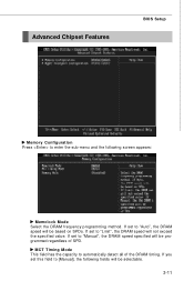
If set to "Manual", the DRAM speed specified will be selectable. 3-11 If set to "Auto", the DRAM speed will be programmed regardless of the DRAM timing. If you set to "Limit", the DRAM speed will be based on SPDs. If set this field to [Manual], the following screen appears: Memclock Mode Select the DRAM frequency programming method. Advanced Chipset Features BIOS Setup Memory Configuration Press to enter the sub-menu and the following fields will not exceed the specified value. MCT Timing Mode This field has the capacity to automatically detect all of SPD.
If set to "Manual", the DRAM speed specified will be selectable. 3-11 If set to "Auto", the DRAM speed will be programmed regardless of the DRAM timing. If you set to "Limit", the DRAM speed will be based on SPDs. If set this field to [Manual], the following screen appears: Memclock Mode Select the DRAM frequency programming method. Advanced Chipset Features BIOS Setup Memory Configuration Press to enter the sub-menu and the following fields will not exceed the specified value. MCT Timing Mode This field has the capacity to automatically detect all of SPD.

User Guide
Page 50
... USB / 2.0 Controller This setting allows you to enable/ disable BIOS to used PCI busmastering for reading/ writing to IDE drives. 3-13 Onboard LAN Controller These items are used to enable/disable the onboard LAN controller. ...
... USB / 2.0 Controller This setting allows you to enable/ disable BIOS to used PCI busmastering for reading/ writing to IDE drives. 3-13 Onboard LAN Controller These items are used to enable/disable the onboard LAN controller. ...
User Guide
Page 52
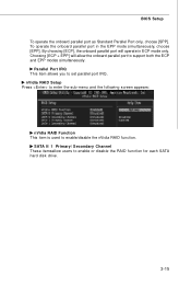
... RAID Setup Press to enter the sub-menu and the following screen appears: nVidia RAID Function This item is used to set parallel port IRQ. BIOS Setup To operate the onboard parallel port as Standard Parallel Port only, choose [SPP]. To operate the onboard parallel port in ECP mode only. SATA...
... RAID Setup Press to enter the sub-menu and the following screen appears: nVidia RAID Function This item is used to set parallel port IRQ. BIOS Setup To operate the onboard parallel port as Standard Parallel Port only, choose [SPP]. To operate the onboard parallel port in ECP mode only. SATA...


