User Guide
Page 9
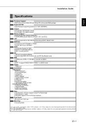
...2 PCI Express x 1 slots - 2 PCI slots, support 3.3V/ 5V PCI bus interface Form Factor - Azalis 1.0 Audio solution IDE - 1 IDE port controlled by SB600 RAID - ATX (24.5 cm X 30.5 cm) Mounting - 9 mounting holes *For the latest information about CPU, please visit http:// www.ms i.com. com.t w/pro gram/ product s/ mai ...nboard/ mbd/ pro_mbd_trp_lis t.php En-1 tw/pro gram/product s/mainboard/ mbd/ pro_ mbd_ cpu_ support. Transfer rate is up to 400 Mb/s Audio - AMD® Athlon 64 X2, Athlon 64 and Athlon FX in ...
...2 PCI Express x 1 slots - 2 PCI slots, support 3.3V/ 5V PCI bus interface Form Factor - Azalis 1.0 Audio solution IDE - 1 IDE port controlled by SB600 RAID - ATX (24.5 cm X 30.5 cm) Mounting - 9 mounting holes *For the latest information about CPU, please visit http:// www.ms i.com. com.t w/pro gram/ product s/ mai ...nboard/ mbd/ pro_mbd_trp_lis t.php En-1 tw/pro gram/product s/mainboard/ mbd/ pro_ mbd_ cpu_ support. Transfer rate is up to 400 Mb/s Audio - AMD® Athlon 64 X2, Athlon 64 and Athlon FX in ...
User Guide
Page 10
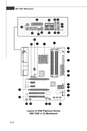
MS-7280 Mainboard 30 35 38 41 37 29 40 31 43 34 36 39 44 23 25 4 1 3 15 Winbond 16 5 21 6 4 7 26 20 8 27 14 12 10 19 9 Layout of K9A Platinum Series (MS-7280 v1.X) Mainboard En-2
MS-7280 Mainboard 30 35 38 41 37 29 40 31 43 34 36 39 44 23 25 4 1 3 15 Winbond 16 5 21 6 4 7 26 20 8 27 14 12 10 19 9 Layout of K9A Platinum Series (MS-7280 v1.X) Mainboard En-2
User Guide
Page 11
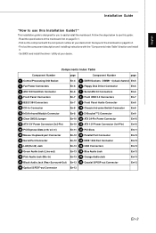
...-8 16 IrDA Infrared Module Connector En-8 19 D-BracketTM 2 Connector En-9 20 Clear CMOS Jumper En-10 21 ATX 24-Pin Power Connector En-10 23 ATX 12V Power Connector (2x2-Pin) En-10 25 ATX 12V Power Connector (1x4-Pin) En-10 26 PCI Express Slots (x16/ x4/ x1) En-11 27... "How to use this guide: - Find out the component description and installing instructions with the component number at your desire from the layout of the mainboard first on page En-2. - Set BIOS and install the driver / utiltity at your desire. This installation guide is designed for you to easily install ...
...-8 16 IrDA Infrared Module Connector En-8 19 D-BracketTM 2 Connector En-9 20 Clear CMOS Jumper En-10 21 ATX 24-Pin Power Connector En-10 23 ATX 12V Power Connector (2x2-Pin) En-10 25 ATX 12V Power Connector (1x4-Pin) En-10 26 PCI Express Slots (x16/ x4/ x1) En-11 27... "How to use this guide: - Find out the component description and installing instructions with the component number at your desire from the layout of the mainboard first on page En-2. - Set BIOS and install the driver / utiltity at your desire. This installation guide is designed for you to easily install ...
User Guide
Page 12
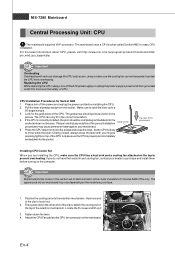
... the CPU While replacing the CPU, always turn off theATX power supply or unplug the power supply's power cord from overheating. The mainboard uses a CPU socket called Socket AM2 for Socket AM2 CPUs only. Press the CPU down the lever. 4. The gold arrow should... be completely embedded into the socket and close the lever with your mainboard. 5. If you purchase. 1. For the latest information about CPU, please visit http://www.msi.com.tw/program/products/mainboard/mbd/ pro_mbd_cpu_support.php Important Overheating Overheating will seriously damage the CPU and system, ...
... the CPU While replacing the CPU, always turn off theATX power supply or unplug the power supply's power cord from overheating. The mainboard uses a CPU socket called Socket AM2 for Socket AM2 CPUs only. Press the CPU down the lever. 4. The gold arrow should... be completely embedded into the socket and close the lever with your mainboard. 5. If you purchase. 1. For the latest information about CPU, please visit http://www.msi.com.tw/program/products/mainboard/mbd/ pro_mbd_cpu_support.php Important Overheating Overheating will seriously damage the CPU and system, ...
User Guide
Page 14
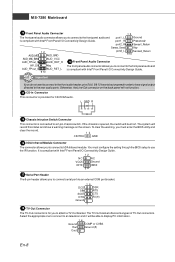
...) SATA 2.0 connector (Purple) Take out the dust cover and connect to the hard disk devices Connect to 133 megabytes (MB) per second. If the mainboard has a System Hardware Monitor chipset onboard, you must use a specially designed fan with 3 or 4 pins are both available for CPUFAN. 5 Floppy Disk... Drive Connector (FDD connector) The mainboard provides a standard floppy disk drive connector that the red wire is the positive and should be connected to Slave mode by hard disk vendors for...
...) SATA 2.0 connector (Purple) Take out the dust cover and connect to the hard disk devices Connect to 133 megabytes (MB) per second. If the mainboard has a System Hardware Monitor chipset onboard, you must use a specially designed fan with 3 or 4 pins are both available for CPUFAN. 5 Floppy Disk... Drive Connector (FDD connector) The mainboard provides a standard floppy disk drive connector that the red wire is the positive and should be connected to Slave mode by hard disk vendors for...
User Guide
Page 16
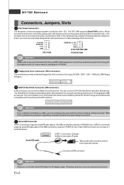
...-In Connector This connector is compliant with Intel® Front Panel I /O Connectivity Design Guide. Important If you to connect to IrDA Infrared module. MS-7280 Mainboard 12 Front Panel Audio Connector 12 The front panel audio connector allows you to connect to the front panel audio and is provided for you...
...-In Connector This connector is compliant with Intel® Front Panel I /O Connectivity Design Guide. Important If you to connect to IrDA Infrared module. MS-7280 Mainboard 12 Front Panel Audio Connector 12 The front panel audio connector allows you to connect to the front panel audio and is provided for you...
User Guide
Page 18
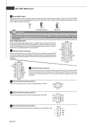
... (1x4-Pin) These 12V power connectors is off . To connect theATX 24-pin power supply, make sure the plug of the mainboard. +3.3V +12V +12V 5VSB GND +5V +5V +5V 21 ATX 24-Pin Power Connector PWR OK GND NC GND This connector allowsyou to the graphics card. 1 2 3 4 5V GND GND 12V... sure the plug of system configuration. Power Supply Attachment 12 24 Before inserting the power supplyconnector, always make sure that no damage will damage the mainboard. With the CMOS RAM, the system can clear CMOS by shorting 2-3 pin while the system is used to provide power to connect anATX 24-...
... (1x4-Pin) These 12V power connectors is off . To connect theATX 24-pin power supply, make sure the plug of the mainboard. +3.3V +12V +12V 5VSB GND +5V +5V +5V 21 ATX 24-Pin Power Connector PWR OK GND NC GND This connector allowsyou to the graphics card. 1 2 3 4 5V GND GND 12V... sure the plug of system configuration. Power Supply Attachment 12 24 Before inserting the power supplyconnector, always make sure that no damage will damage the mainboard. With the CMOS RAM, the system can clear CMOS by shorting 2-3 pin while the system is used to provide power to connect anATX 24-...
User Guide
Page 20
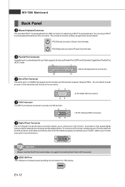
... support connecting the D-Sub to connect an LCD monitor. To connect a LCD monitor, simplyplug your monitor manual for attaching a PS/2® mouse/keyboard. MS-7280 Mainboard Back Panel 29 Mouse/Keyboard Connector The standard PS/2® mouse/keyboard mini DIN connector for more information.) 1 8 17 24 Important Please note that sends...
... support connecting the D-Sub to connect an LCD monitor. To connect a LCD monitor, simplyplug your monitor manual for attaching a PS/2® mouse/keyboard. MS-7280 Mainboard Back Panel 29 Mouse/Keyboard Connector The standard PS/2® mouse/keyboard mini DIN connector for more information.) 1 8 17 24 Important Please note that sends...
User Guide
Page 22
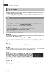
..., V = VIA, N = Nvidia, U = ULi. 7th - 8th digit refers to the customer as shown in the right view) appears to the left of the screen. MS-7280 Mainboard BIOS Setup This chapter provides basic information on the screen during the system booting up, and requests you to run the Setup program when: * An...
..., V = VIA, N = Nvidia, U = ULi. 7th - 8th digit refers to the customer as shown in the right view) appears to the left of the screen. MS-7280 Mainboard BIOS Setup This chapter provides basic information on the screen during the system booting up, and requests you to run the Setup program when: * An...
User Guide
Page 23
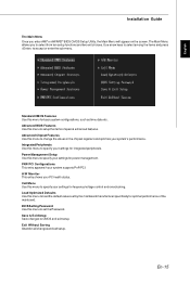
... status. BIOS Setting Password Use this menu for integrated peripherals. Standard CMOS Features Use this menu to setup the items of the mainboard. Advanced BIOS Features Use this menu to accept or enter the sub-menu. H/W Monitor This entry shows your system supports PnP/PCI... among the items and press to specify your settings for power management. Power Management Setup Use this menu to set by the mainboard manufacturer specifically for fequency/voltage control and overclocking. Save & Exit Setup Save changes to specify your settings for optimal performance of special...
... status. BIOS Setting Password Use this menu for integrated peripherals. Standard CMOS Features Use this menu to setup the items of the mainboard. Advanced BIOS Features Use this menu to accept or enter the sub-menu. H/W Monitor This entry shows your system supports PnP/PCI... among the items and press to specify your settings for power management. Power Management Setup Use this menu to set by the mainboard manufacturer specifically for fequency/voltage control and overclocking. Save & Exit Setup Save changes to specify your settings for optimal performance of special...
User Guide
Page 24
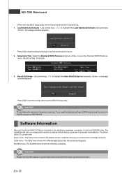
...Important The configuration above are for optimal system performance. 2. If you need the detailed settings of BIOS, please see the manual in the mainboard package, and place it into the CD-ROM driver. The Driver menu shows the available drivers. Adjust the Date, Time fields. 3....The Utility menu shows the software applications that is included in English version on MSI website. The WebSite menu shows the necessarywebsites. En-16 Software Information Take out the Driver/Utility CD that the mainboard supports. The installation will auto-run, simply click the driver or utiltiyand follow...
...Important The configuration above are for optimal system performance. 2. If you need the detailed settings of BIOS, please see the manual in the mainboard package, and place it into the CD-ROM driver. The Driver menu shows the available drivers. Adjust the Date, Time fields. 3....The Utility menu shows the software applications that is included in English version on MSI website. The WebSite menu shows the necessarywebsites. En-16 Software Information Take out the Driver/Utility CD that the mainboard supports. The installation will auto-run, simply click the driver or utiltiyand follow...
User Guide
Page 26
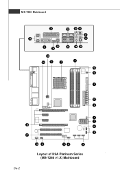
MS-7280 Mainboard 30 35 38 41 37 29 40 31 43 34 36 39 44 23 25 4 1 3 15 Winbond 16 5 21 6 4 7 26 20 8 27 14 12 10 19 9 Layout of K9A Platinum Series (MS-7280 v1.X) Mainboard De-2
MS-7280 Mainboard 30 35 38 41 37 29 40 31 43 34 36 39 44 23 25 4 1 3 15 Winbond 16 5 21 6 4 7 26 20 8 27 14 12 10 19 9 Layout of K9A Platinum Series (MS-7280 v1.X) Mainboard De-2


