User Guide
Page 2
...W indows® 95/98/2000/NT/XP are registered trademarks or trademarks of International Business Machines Corporation. Visit the MSI website for FAQ, technical guide, BIOS updates, driver updates, and other countries. PS/2 and OS®/2 are under continual improvement and we reserve the ...registered trademarks of NVIDIA Corporation in the United States and/or other information: http://www.msi.com.tw/program/service/faq/ faq/esc_faq_list.php Contact our technical staff at: http://support.msi.com.tw/ ii AMD, Athlon™, Athlon™ XP, Thoroughbred™, and Duron...
...W indows® 95/98/2000/NT/XP are registered trademarks or trademarks of International Business Machines Corporation. Visit the MSI website for FAQ, technical guide, BIOS updates, driver updates, and other countries. PS/2 and OS®/2 are under continual improvement and we reserve the ...registered trademarks of NVIDIA Corporation in the United States and/or other information: http://www.msi.com.tw/program/service/faq/ faq/esc_faq_list.php Contact our technical staff at: http://support.msi.com.tw/ ii AMD, Athlon™, Athlon™ XP, Thoroughbred™, and Duron...
User Guide
Page 8
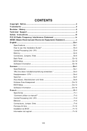
... to use this Installation Guide En-3 Central Processing Unit: CPU En-4 Memory ...En-5 Connectors, Jumpers, Slots En-6 Back Panel ...En-12 BIOS Setup ...En-14 Software Information En-16 G e rm an ...De-1 Spezifikationen De-1 "W ie Sie diese Installationsanleitung verwenden De-3 Hauptprozessor: CPU... De-4 Speicher ...De-5 Anschlüsse, Steckbrücken und Slots De-6 Hinteres Anschlusspaneel De-12 BIOS Setup ...De-14 Software Information De-16 French ...Fr-1 Spécificités ...Fr-1 "Comment utiliser ce manuel Fr-3 Central...
... to use this Installation Guide En-3 Central Processing Unit: CPU En-4 Memory ...En-5 Connectors, Jumpers, Slots En-6 Back Panel ...En-12 BIOS Setup ...En-14 Software Information En-16 G e rm an ...De-1 Spezifikationen De-1 "W ie Sie diese Installationsanleitung verwenden De-3 Hauptprozessor: CPU... De-4 Speicher ...De-5 Anschlüsse, Steckbrücken und Slots De-6 Hinteres Anschlusspaneel De-12 BIOS Setup ...De-14 Software Information De-16 French ...Fr-1 Spécificités ...Fr-1 "Comment utiliser ce manuel Fr-3 Central...
User Guide
Page 11
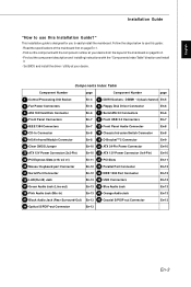
... number at your desire from the layout of the mainboard first on page En-2. - English Installation Guide "How to use this Installation Guide?" Set BIOS and install the driver / utiltity at your desire. Components Index Table Component Number page Component Number page 1 Central Processing Unit Socket En-4 3 DDRII...IrDA Infrared Module Connector En-8 19 D-BracketTM 2 Connector En-9 20 Clear CMOS Jumper En-10 21 ATX 24-Pin Power Connector En-10 23 ATX 12V Power Connector (2x2-Pin) En-10 25 ATX 12V Power Connector (1x4-Pin) En-10 26 PCI Express Slots (x16/ x4/ x1) En-11...
... number at your desire from the layout of the mainboard first on page En-2. - English Installation Guide "How to use this Installation Guide?" Set BIOS and install the driver / utiltity at your desire. Components Index Table Component Number page Component Number page 1 Central Processing Unit Socket En-4 3 DDRII...IrDA Infrared Module Connector En-8 19 D-BracketTM 2 Connector En-9 20 Clear CMOS Jumper En-10 21 ATX 24-Pin Power Connector En-10 23 ATX 12V Power Connector (2x2-Pin) En-10 25 ATX 12V Power Connector (1x4-Pin) En-10 26 PCI Express Slots (x16/ x4/ x1) En-11...
User Guide
Page 16
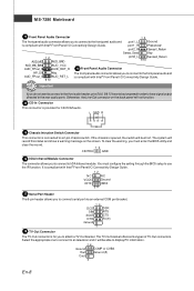
... front panel audio and is for CD-ROM audio. To clear the warning, you must configure the setting through the BIOS setup to IrDA Infrared module. You must enter the BIOS utility and clear the record. 12 CINTRU GND 16 IrDA Infrared Module Connector The connector allows you to connect to use...
... front panel audio and is for CD-ROM audio. To clear the warning, you must configure the setting through the BIOS setup to IrDA Infrared module. You must enter the BIOS utility and clear the record. 12 CINTRU GND 16 IrDA Infrared Module Connector The connector allows you to connect to use...
User Guide
Page 17
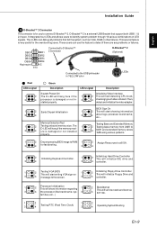
... 4 INT 19h. Initializing Video Interface 2 This will start showing information 3 4 about logo, processor brand name, etc... properly. 1 2 Decompressing BIOS image to RAM 1 2 Assign Resources to all problems that support both USB1.1 & 2.0 spec. These users can debug all ISA. 3 4 for...Initializing Keyboard Controller. 1 2 Initializing Hard Drive Controller This will initialize IDE drive and 3 4 3 4 controller. 1 2 Testing VGA BIOS 1 2 Initializing Floppy Drive Controller This will start writing VGA sign-on This will initialize Floppy Drive and 3 4 message to the USB...
... 4 INT 19h. Initializing Video Interface 2 This will start showing information 3 4 about logo, processor brand name, etc... properly. 1 2 Decompressing BIOS image to RAM 1 2 Assign Resources to all problems that support both USB1.1 & 2.0 spec. These users can debug all ISA. 3 4 for...Initializing Keyboard Controller. 1 2 Initializing Hard Drive Controller This will initialize IDE drive and 3 4 3 4 controller. 1 2 Testing VGA BIOS 1 2 Initializing Floppy Drive Controller This will start writing VGA sign-on This will initialize Floppy Drive and 3 4 message to the USB...
User Guide
Page 19
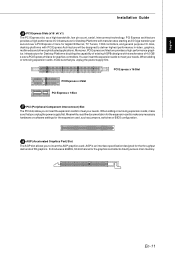
... the graphics controller to meet your needs. English Installation Guide 26 PCI Express Slots (x16/ x4/ x1) The PCI Express slot, as jumpers, switches or BIOS configuration. 28 AGP (Accelerated Graphics Port) Slot The AGP slot allows you to insert the expansion cards to directlyaccess main memory.
... the graphics controller to meet your needs. English Installation Guide 26 PCI Express Slots (x16/ x4/ x1) The PCI Express slot, as jumpers, switches or BIOS configuration. 28 AGP (Accelerated Graphics Port) Slot The AGP slot allows you to insert the expansion cards to directlyaccess main memory.
User Guide
Page 22
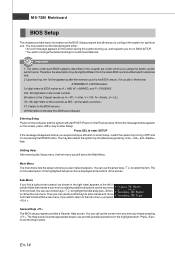
... features. Entering Setup Power on the computer and the system will see is usually in the format: A7280AMS V1.0 051506 where: 1st digit refers to BIOS maker as A = AMI, W = AWARD, and P = PHOENIX. 2nd - 5th digit refers to the model number. 6th refers to the Chipset vender as A = ATi, I = Intel, V = VIA, ... up , and requests you still wish to enter Setup, restart the system by simply pressing . You may be slightly different from the latest BIOS and should be launched from this screen from field to field within a sub-menu. Press DEL to enter SETUP If the message disappears before...
... features. Entering Setup Power on the computer and the system will see is usually in the format: A7280AMS V1.0 051506 where: 1st digit refers to BIOS maker as A = AMI, W = AWARD, and P = PHOENIX. 2nd - 5th digit refers to the model number. 6th refers to the Chipset vender as A = ATi, I = Intel, V = VIA, ... up , and requests you still wish to enter Setup, restart the system by simply pressing . You may be slightly different from the latest BIOS and should be launched from this screen from field to field within a sub-menu. Press DEL to enter SETUP If the message disappears before...
User Guide
Page 23
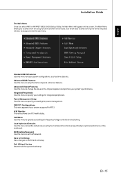
... performance. Integrated Peripherals Use this menu to setup the items of the mainboard. PNP/PCI Configurations This entry appears if your settings for power management. BIOS Setting Password Use this menu to specify your PC health status. The Main Menu allows you enter AMI® or AWARD®...Utility, the Main Menu will appear on the screen. Use arrow keys to select among the items and press to CMOS and exit setup. Advanced BIOS Features Use this menu to specify your system supports PnP/PCI. Save & Exit Setup Save changes to accept or enter the sub-menu. Power Management...
... performance. Integrated Peripherals Use this menu to setup the items of the mainboard. PNP/PCI Configurations This entry appears if your settings for power management. BIOS Setting Password Use this menu to specify your PC health status. The Main Menu allows you enter AMI® or AWARD®...Utility, the Main Menu will appear on the screen. Use arrow keys to select among the items and press to CMOS and exit setup. Advanced BIOS Features Use this menu to specify your system supports PnP/PCI. Save & Exit Setup Save changes to accept or enter the sub-menu. Power Management...
User Guide
Page 24
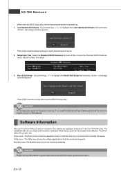
...and to enter the Standard CMOS Features- The Utility menu shows the software applications that is included in English version on MSI website. If you need the detailed settings of BIOS, please see the manual in the mainboard package, and place it into the CD-ROM driver. Important Please visit ...the MSI website to load the default settings for general use only. The Driver menu shows the available drivers. Setup Date/ Time : ...
...and to enter the Standard CMOS Features- The Utility menu shows the software applications that is included in English version on MSI website. If you need the detailed settings of BIOS, please see the manual in the mainboard package, and place it into the CD-ROM driver. Important Please visit ...the MSI website to load the default settings for general use only. The Driver menu shows the available drivers. Setup Date/ Time : ...


