User Guide
Page 4
.... 8. Always read the safety instructions carefully. 2. Lay this equipment away from overheating. Place the power cord such a way that could damage or cause electrical shock. 11. All cautions and warnings on card or module. 9. Do not leave this User's Manual for technical guide, BIOS updates, driver updates, and other information: http://www.msi.com.tw & http://www.msi. Replace only with your system...
.... 8. Always read the safety instructions carefully. 2. Lay this equipment away from overheating. Place the power cord such a way that could damage or cause electrical shock. 11. All cautions and warnings on card or module. 9. Do not leave this User's Manual for technical guide, BIOS updates, driver updates, and other information: http://www.msi.com.tw & http://www.msi. Replace only with your system...
User Guide
Page 5
... for Socket 939 2-4 Installing AMD Athlon64 / Athlon 64 FX CPU Cooler Set 2-5 Memory ...2-7 DIMM Module Combination 2-7 Recommended Memory Combination List 2-8 Installing DDR Modules 2-9 Power Supply 2-10 ATX 20-Pin Power Connector: JWR1 2-10 ATX 12V Power Connector: JPW1 2-10 Back Panel ...2-11 Mouse Connector (Green 2-11 Keyboard Connector (Purple 2-11 Serial Port Connector 2-12 USB Connectors 2-12 IEEE1394 Ports (Optional 2-12 RJ-45 LAN Jack 2-13 Audio Port Connectors 2-14 Parallel Port Connector: LPT1 2-15 Connectors ...2-16 Floppy Disk Drive Connector: FDD1 2-16 Fan Power...
... for Socket 939 2-4 Installing AMD Athlon64 / Athlon 64 FX CPU Cooler Set 2-5 Memory ...2-7 DIMM Module Combination 2-7 Recommended Memory Combination List 2-8 Installing DDR Modules 2-9 Power Supply 2-10 ATX 20-Pin Power Connector: JWR1 2-10 ATX 12V Power Connector: JPW1 2-10 Back Panel ...2-11 Mouse Connector (Green 2-11 Keyboard Connector (Purple 2-11 Serial Port Connector 2-12 USB Connectors 2-12 IEEE1394 Ports (Optional 2-12 RJ-45 LAN Jack 2-13 Audio Port Connectors 2-14 Parallel Port Connector: LPT1 2-15 Connectors ...2-16 Floppy Disk Drive Connector: FDD1 2-16 Fan Power...
User Guide
Page 6
...supported 4-12 Core Center (for AMD K8 Processor 4-14 Audio Speaker Setting 4-16 Power on Agent 4-18 vi Chassis Intrusion Switch Connector: JCASE1 2-22 Power Saving Switch Connector: JGS1 2-22 D-Bracket™ 2 Connector: JLED (Optional 2-22 Jumpers ...2-25 Clear CMOS Jumper: JBAT1 2-25 Slots ...2-26 AGP (Accelerated Graphics Port) Slot 2-26 PCI (Peripheral Component Interconnect) Slots 2-26 PCI Interrupt Request Routing 2-26 Chapter 3. BIOS Setup 3-1 Entering Setup ...3-2 Selecting the First Boot Device 3-2 Control Keys 3-3 Getting Help 3-3 The Main Menu 3-4 Standard CMOS...
...supported 4-12 Core Center (for AMD K8 Processor 4-14 Audio Speaker Setting 4-16 Power on Agent 4-18 vi Chassis Intrusion Switch Connector: JCASE1 2-22 Power Saving Switch Connector: JGS1 2-22 D-Bracket™ 2 Connector: JLED (Optional 2-22 Jumpers ...2-25 Clear CMOS Jumper: JBAT1 2-25 Slots ...2-26 AGP (Accelerated Graphics Port) Slot 2-26 PCI (Peripheral Component Interconnect) Slots 2-26 PCI Interrupt Request Routing 2-26 Chapter 3. BIOS Setup 3-1 Entering Setup ...3-2 Selecting the First Boot Device 3-2 Control Keys 3-3 Getting Help 3-3 The Main Menu 3-4 Standard CMOS...
User Guide
Page 7
... / Serial ATA RAID (Optional) Introduction 5-1 Introduction ...5-2 System BIOS Setup 5-3 VIA VT8237 Serial ATA RAID 5-4 Create Your RAID Disk Array Under DOS 5-5 Create Disk Array 5-6 Delete Disk Array 5-8 Create and Delete Spare Hard Drive 5-9 View Serial Number of Hard Drive 5-9 Duplicate Critical RAID 1 Array 5-10 Rebuild Broken RAID 1 Array 5-10 Installing Operating System & Drivers 5-12 Install Driver in Windows OS 5-12 VIA SATA RAID Drivers 5-13 Using VIA RAID Tool 5-14 Promise FastTrak579 Parallel ATA / Serial ATA RAID (Optional 5-16 Create Your RAID Disk...
... / Serial ATA RAID (Optional) Introduction 5-1 Introduction ...5-2 System BIOS Setup 5-3 VIA VT8237 Serial ATA RAID 5-4 Create Your RAID Disk Array Under DOS 5-5 Create Disk Array 5-6 Delete Disk Array 5-8 Create and Delete Spare Hard Drive 5-9 View Serial Number of Hard Drive 5-9 Duplicate Critical RAID 1 Array 5-10 Rebuild Broken RAID 1 Array 5-10 Installing Operating System & Drivers 5-12 Install Driver in Windows OS 5-12 VIA SATA RAID Drivers 5-13 Using VIA RAID Tool 5-14 Promise FastTrak579 Parallel ATA / Serial ATA RAID (Optional 5-16 Create Your RAID Disk...
User Guide
Page 10
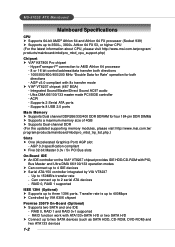
... Graphics Port) AGP slot - RAID 0, RAID 1 supported IEEE 1394 (Optional) h Supports up to AMD Athlon 64 processor - 8 or 16 bit control/address/data transfer both directions - RAID 0, RAID 1 and RAID 0+1 supported - Integrated Sound Blaster/Direct Sound AC97 audio - Ultra DMA 66/100/133 master mode PCI EIDE controller - Transfer rate is up to 4 IDE devices h Serial ATA/150 controller integrated by VIA 6306 chipset Promise 20579 On-Board (Optional) h Supports two SATA and one IDE - Supports 2 Serial ATA ports - Up to two SATA devices (such as SATA HDD, CD-ROM, DVD-ROM...
... Graphics Port) AGP slot - RAID 0, RAID 1 supported IEEE 1394 (Optional) h Supports up to AMD Athlon 64 processor - 8 or 16 bit control/address/data transfer both directions - RAID 0, RAID 1 and RAID 0+1 supported - Integrated Sound Blaster/Direct Sound AC97 audio - Ultra DMA 66/100/133 master mode PCI EIDE controller - Transfer rate is up to 4 IDE devices h Serial ATA/150 controller integrated by VIA 6306 chipset Promise 20579 On-Board (Optional) h Supports two SATA and one IDE - Supports 2 Serial ATA ports - Up to two SATA devices (such as SATA HDD, CD-ROM, DVD-ROM...

User Guide
Page 11
... I) h RAID Smart function h SATA ATAPI device compatible On-Board Peripherals h On-Board Peripherals include: - 1 floppy port supports 1 FDD with AC97 v2.3 Spec - Integrated Fast Ethernet MAC and PHY in their SATA hard drive. Please note that users cannot install OS, neither WinME nor Win98, in one chip - As the end user cannot boot without SP4, a combination installation CD must be used as a normal storage device. 2. Supports 10Mb/s, 100Mb/s and 1000Mb/s multi-mode BIOS h The mainboard BIOS provides "Plug & Play" BIOS...
... I) h RAID Smart function h SATA ATAPI device compatible On-Board Peripherals h On-Board Peripherals include: - 1 floppy port supports 1 FDD with AC97 v2.3 Spec - Integrated Fast Ethernet MAC and PHY in their SATA hard drive. Please note that users cannot install OS, neither WinME nor Win98, in one chip - As the end user cannot boot without SP4, a combination installation CD must be used as a normal storage device. 2. Supports 10Mb/s, 100Mb/s and 1000Mb/s multi-mode BIOS h The mainboard BIOS provides "Plug & Play" BIOS...

User Guide
Page 20
...) modules and supports the memory size up to 4GB. Each DIMM slot supports up to a maximum size of different type and density on the slots. Please note that each DIMM can work respectively for singlechannel DDR, but there are necessary while using dual-channel DDR, or instability may install memory modules of 1GB. Hardware Setup Memory The mainboard provides 4 slots for detailed dual-channel DDR. Other combination not listed below ). You...
...) modules and supports the memory size up to 4GB. Each DIMM slot supports up to a maximum size of different type and density on the slots. Please note that each DIMM can work respectively for singlechannel DDR, but there are necessary while using dual-channel DDR, or instability may install memory modules of 1GB. Hardware Setup Memory The mainboard provides 4 slots for detailed dual-channel DDR. Other combination not listed below ). You...
User Guide
Page 39
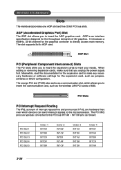
... 32-bit PCI bus slots. AGP is an interface specification designed for the throughput demands of MSI. When adding or removing expansion cards, make any necessary hardware or software settings for the graphics controller to insert the AGP graphics card. The PCI IRQ pins are hardware lines over which allows you to directly access main memory. AGP (Accelerated Graphics Port) Slot The AGP slot allows you to the PCI bus INT A# ~ INT D# pins as the wireless LAN PCI cards...
... 32-bit PCI bus slots. AGP is an interface specification designed for the throughput demands of MSI. When adding or removing expansion cards, make any necessary hardware or software settings for the graphics controller to insert the AGP graphics card. The PCI IRQ pins are hardware lines over which allows you to directly access main memory. AGP (Accelerated Graphics Port) Slot The AGP slot allows you to the PCI bus INT A# ~ INT D# pins as the wireless LAN PCI cards...
User Guide
Page 41
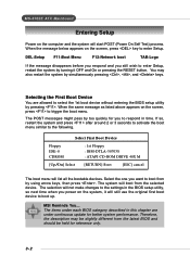
... message as listed above appears on the screen, press to enter Setup. The items under continuous update for reference only. 3-2 DEL:Setup F11:Boot Menu F12:Network boot TAB:Logo If the message disappears before you respond and you to boot up. Select First Boot Device Floppy IDE-0 CDROM : 1st Floppy : IBM-DTLA-307038 : ATAPI CD-ROM DRIVE 40X M [Up/Dn] Select [RETURN] Boot [ESC] cancel The boot menu will start POST (Power On...
... message as listed above appears on the screen, press to enter Setup. The items under continuous update for reference only. 3-2 DEL:Setup F11:Boot Menu F12:Network boot TAB:Logo If the message disappears before you respond and you to boot up. Select First Boot Device Floppy IDE-0 CDROM : 1st Floppy : IBM-DTLA-307038 : ATAPI CD-ROM DRIVE 40X M [Up/Dn] Select [RETURN] Boot [ESC] cancel The boot menu will start POST (Power On...
User Guide
Page 48
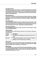
...; operating system with DRAM larger than 64MB. When enabled, the BIOS will activate the floppy disk drives during the boot process: the drive activity light will come on . Settings are described below: Option [Setup] [Always] Description The password prompt appears only when end users try to a safe place before the hard disk becomes offline. To find out which MPS (Multi-Processor Specification) version to use the arrow keys on the numeric keypad...
...; operating system with DRAM larger than 64MB. When enabled, the BIOS will activate the floppy disk drives during the boot process: the drive activity light will come on . Settings are described below: Option [Setup] [Always] Description The password prompt appears only when end users try to a safe place before the hard disk becomes offline. To find out which MPS (Multi-Processor Specification) version to use the arrow keys on the numeric keypad...

User Guide
Page 50
... main memory that remains powered while most other hard- If your BIOS supports S3 sleep mode. BIOS Setup Power Management Features MSI Reminds You... The information stored in S1(POS) or S3(STR) fashion through the setting of this section are : [S1/POS] The S1 sleep mode is shortened when you can choose to enter the Standby mode in memory will need an AGP driver to initialize the VGA card. Call VGA BIOS...
... main memory that remains powered while most other hard- If your BIOS supports S3 sleep mode. BIOS Setup Power Management Features MSI Reminds You... The information stored in S1(POS) or S3(STR) fashion through the setting of this section are : [S1/POS] The S1 sleep mode is shortened when you can choose to enter the Standby mode in memory will need an AGP driver to initialize the VGA card. Call VGA BIOS...

User Guide
Page 55
... disable the operation mode for serial port 2. Setting options: [Enabled], [Disabled]. Setting options: [1.6uS], [3/16 Baud], [ASKIR]. 3-16 Serial Port A These items specify the base I/O port addresses of the onboard Serial Port A (COM A). Enables the onboard Floppy controller. Selecting [Auto] allows AMIBIOS to enable the onboard Floppy controller or not. Floppy Controller This is set to [Enabled], this setting allows you to enter the sub-menu screen. IR Mode When IR Function is used to enable or disable the onboard Floppy controller. MS-6702E ATX Mainboard Set...
... disable the operation mode for serial port 2. Setting options: [Enabled], [Disabled]. Setting options: [1.6uS], [3/16 Baud], [ASKIR]. 3-16 Serial Port A These items specify the base I/O port addresses of the onboard Serial Port A (COM A). Enables the onboard Floppy controller. Selecting [Auto] allows AMIBIOS to enable the onboard Floppy controller or not. Floppy Controller This is set to [Enabled], this setting allows you to enter the sub-menu screen. IR Mode When IR Function is used to enable or disable the onboard Floppy controller. MS-6702E ATX Mainboard Set...

User Guide
Page 61
... overclock the system. AGP Voltage AGP voltage is used to determine the internal clock speed of your AGP display card when overclocking, but the stability may be affected. Setting options: [Auto], [1.55V], [1.60V], [1.65V], [1.70V], [1.75V], [1.80V], [1.85V]. Setting options: [Enabled], [Disabled]. 3-22 AGP Frequency This item allows you to select the CPU Front Side Bus clock frequency (in the field, allowing you to this setting may cause a stability issue, so changing the DRAM voltage for long...
... overclock the system. AGP Voltage AGP voltage is used to determine the internal clock speed of your AGP display card when overclocking, but the stability may be affected. Setting options: [Auto], [1.55V], [1.60V], [1.65V], [1.70V], [1.75V], [1.80V], [1.85V]. Setting options: [Enabled], [Disabled]. 3-22 AGP Frequency This item allows you to select the CPU Front Side Bus clock frequency (in the field, allowing you to this setting may cause a stability issue, so changing the DRAM voltage for long...
User Guide
Page 72
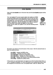
... BIOS/driver version throughout the whole Web site. To use the function, you don't need to the "Live Update Guide" under the "Manual" Tab. 4-9 Live Driver - The Live Update 3™ is displayed. Live Utility - Introduction to start the update process. Updates the VGA driver online. Updates the utilities online. Live VGA BIOS - Click the desired button to DigiCell Live Update Click on the screen. Live OSD - Updates the VGA BIOS online. Updates the drivers online. Updates the firmware of the screen...
... BIOS/driver version throughout the whole Web site. To use the function, you don't need to the "Live Update Guide" under the "Manual" Tab. 4-9 Live Driver - The Live Update 3™ is displayed. Live Utility - Introduction to start the update process. Updates the VGA driver online. Updates the utilities online. Live VGA BIOS - Click the desired button to DigiCell Live Update Click on the screen. Live OSD - Updates the VGA BIOS online. Updates the drivers online. Updates the firmware of the screen...

User Guide
Page 86
..., select OnBoard PCI Controller, and set the controller [SATA] or [RAID] proceed to Installing Software Drivers. 5-3 VIA VT8237 Serial ATA RAID & Promise FastTrak 579 Parallel ATA / Serial ATA RAID Introduction System BIOS Setup Before you set the P20579 S.ATA Controller to [SATA] or [RAID] or [Disabled]. As to VIA VT8237 Serial ATA RAID, Under Integrated Peripherals, select OnChip SATA IDE Controller, and select [Enabled] or [Disabled]. For AMI BIOS: DEL: Setup F11: Boot Menu F12: Network boot TAB: Logo Once you enter BIOS Setup Utility, the Main Menu will start POST (Power On...
..., select OnBoard PCI Controller, and set the controller [SATA] or [RAID] proceed to Installing Software Drivers. 5-3 VIA VT8237 Serial ATA RAID & Promise FastTrak 579 Parallel ATA / Serial ATA RAID Introduction System BIOS Setup Before you set the P20579 S.ATA Controller to [SATA] or [RAID] or [Disabled]. As to VIA VT8237 Serial ATA RAID, Under Integrated Peripherals, select OnChip SATA IDE Controller, and select [Enabled] or [Disabled]. For AMI BIOS: DEL: Setup F11: Boot Menu F12: Network boot TAB: Logo Once you enter BIOS Setup Utility, the Main Menu will start POST (Power On...
User Guide
Page 95
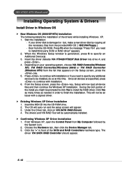
..., choose VIA RAID Controller(Windows XP), VIA RAID Controller(Windows 2000) or VIA RAID Controller (Windows NT4) from the provided MSI CD: [ \IDE\VIA\Floppy ] - Depending on VIA SATA RAID Drivers. 4. Press to continue with a signed driver. Once all device files and then continue the Windows XP installation. Setup will appear. 3. MS-6702E ATX Mainboard Installing Operating System & Drivers Install Driver in Windows OS h New Windows OS (2000/XP/NT4) Installation The following details the installation of the SCSI and RAID Controllers hardware type.
..., choose VIA RAID Controller(Windows XP), VIA RAID Controller(Windows 2000) or VIA RAID Controller (Windows NT4) from the provided MSI CD: [ \IDE\VIA\Floppy ] - Depending on VIA SATA RAID Drivers. 4. Press to continue with a signed driver. Once all device files and then continue the Windows XP installation. Setup will appear. 3. MS-6702E ATX Mainboard Installing Operating System & Drivers Install Driver in Windows OS h New Windows OS (2000/XP/NT4) Installation The following details the installation of the SCSI and RAID Controllers hardware type.

User Guide
Page 104
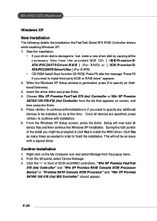
... RAID controllers. When the Windows Server 2003 Setup window is damaged or lost, make a new driver disk by copying all the necessary files from the provided MSI CD: [ \IDE\Promise\SATA\PDC20579\Driver\RAID ] (For RAID) or [ \IDE\Promise\SATA\PDC20579\Driver\Ultra ] (For S-ATA) • CD-ROM Install: Boot from the popup menu. 2. This will now load all devices are specified, press to install the RAID driver. Click the "+" in order to finish the installation. Start the installation...
... RAID controllers. When the Windows Server 2003 Setup window is damaged or lost, make a new driver disk by copying all the necessary files from the provided MSI CD: [ \IDE\Promise\SATA\PDC20579\Driver\RAID ] (For RAID) or [ \IDE\Promise\SATA\PDC20579\Driver\Ultra ] (For S-ATA) • CD-ROM Install: Boot from the popup menu. 2. This will now load all devices are specified, press to install the RAID driver. Click the "+" in order to finish the installation. Start the installation...
User Guide
Page 105
... installation. 6. Start the installation: • If your driver disk is generated, press S to install the RAID driver. Once all device files and then continue the Windows XP installation. During the GUI portion of SCSI and RAID controllers. Confirm Installation 1. Choose Win XP Promise FastTrak 579 (tm) Controller or Win XP Promise SATAII 150 579/518 (tm) Controller from the CD-ROM. From the Windows XP Setup screen, press the Enter. MS-6702E ATX Mainboard Windows XP New Installation...
... installation. 6. Start the installation: • If your driver disk is generated, press S to install the RAID driver. Once all device files and then continue the Windows XP installation. During the GUI portion of SCSI and RAID controllers. Confirm Installation 1. Choose Win XP Promise FastTrak 579 (tm) Controller or Win XP Promise SATAII 150 579/518 (tm) Controller from the CD-ROM. From the Windows XP Setup screen, press the Enter. MS-6702E ATX Mainboard Windows XP New Installation...
User Guide
Page 106
... Setup screen, press Enter. Press to install the RAID driver. From the left panel, select Device Manager. 3. Once all the necessary files from the provided MSI CD: [ \IDE\Promise\SATA\PDC20579\Driver\RAID ] (For RAID) or [ \IDE\Promise\SATA\PDC20579\Driver\Ultra ] (For S-ATA) • CD-ROM Install: Boot from the popup menu. 2. Click Yes as many times as needed in front of the FastTrak Serial ATA RAID Controller drivers while installing Windows 2000. 1. Start the installation: • If your driver disk...
... Setup screen, press Enter. Press to install the RAID driver. From the left panel, select Device Manager. 3. Once all the necessary files from the provided MSI CD: [ \IDE\Promise\SATA\PDC20579\Driver\RAID ] (For RAID) or [ \IDE\Promise\SATA\PDC20579\Driver\Ultra ] (For S-ATA) • CD-ROM Install: Boot from the popup menu. 2. Click Yes as many times as needed in front of the FastTrak Serial ATA RAID Controller drivers while installing Windows 2000. 1. Start the installation: • If your driver disk...
User Guide
Page 122
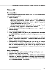
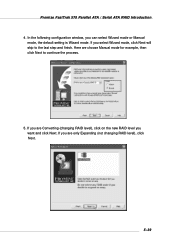
Here we choose Manual mode for example, then click Next to the last step and finish. If you want and click Next. If you are Converting (changing RAID level), click on the new RAID level you are only Expanding (not changing RAID level), click Next. 5-39 In the following configuration window, you select Wizard mode, click Next will skip to continue the process. 5. If you can select Wizard mode or Manual mode, the default setting is Wizard mode. Promise FastTrak 579 Parallel ATA / Serial ATA RAID Introduction 4.
Here we choose Manual mode for example, then click Next to the last step and finish. If you want and click Next. If you are Converting (changing RAID level), click on the new RAID level you are only Expanding (not changing RAID level), click Next. 5-39 In the following configuration window, you select Wizard mode, click Next will skip to continue the process. 5. If you can select Wizard mode or Manual mode, the default setting is Wizard mode. Promise FastTrak 579 Parallel ATA / Serial ATA RAID Introduction 4.
