User Guide
Page 3
.... Copyright Notice The material in this document, but no guarantee is a registered trademark of Microsoft Corporation. Our products are registered trademarks of the Personal Computer Memory Card International Association. Trademarks All trademarks are registered trademarks of their respective owners. PS/2 and OS®/2 are the properties of International Business Machines Corporation...
.... Copyright Notice The material in this document, but no guarantee is a registered trademark of Microsoft Corporation. Our products are registered trademarks of the Personal Computer Memory Card International Association. Trademarks All trademarks are registered trademarks of their respective owners. PS/2 and OS®/2 are the properties of International Business Machines Corporation...
User Guide
Page 5
... Unit: CPU 2-3 CPU Installation Procedures for Socket 939 2-4 Installing AMD Athlon64 CPU Cooler Set 2-5 Memory ...2-7 Introduction to DDR SDRAM 2-7 DIMM Module Combination 2-7 Recommended Memory Combination List 2-8 Installing DDR Modules 2-9 Power Supply 2-10 ATX 20-Pin Power Connector: ATX1 2-10 ATX 12V Power Connector: JPW1 2-10 Important Notification about Power Issue 2-11 Back Panel ...2-12...
... Unit: CPU 2-3 CPU Installation Procedures for Socket 939 2-4 Installing AMD Athlon64 CPU Cooler Set 2-5 Memory ...2-7 Introduction to DDR SDRAM 2-7 DIMM Module Combination 2-7 Recommended Memory Combination List 2-8 Installing DDR Modules 2-9 Power Supply 2-10 ATX 20-Pin Power Connector: ATX1 2-10 ATX 12V Power Connector: JPW1 2-10 Important Notification about Power Issue 2-11 Back Panel ...2-12...
User Guide
Page 9
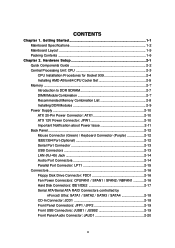
...IEEE 802.3 nVIDIA MAC for four drives - pin DDR DIMMs h Supports a maximum memory size up to 4GB h Supports 2.5v DDR SDRAM DIMM (For the updated supporting memory modules, please visit http://www.msi.com.tw/ program/products/mainboard/mbd/pro_mbd_trp_list.php.) Slots h One AGP (Accelerated Graphics ... 53, or higher CPU (For the latest information about CPU, please visit http://www.msi.com.tw/program/ products/mainboard/mbd/pro_mbd_cpu_support.php) Chipset h nVIDIA nForce3 Ultra - MS-7025 ATX Mainboard Mainboard Specifications CPU h Supports Socket-939 for AMD K8 Athlon 64 FX / Athlon...
...IEEE 802.3 nVIDIA MAC for four drives - pin DDR DIMMs h Supports a maximum memory size up to 4GB h Supports 2.5v DDR SDRAM DIMM (For the updated supporting memory modules, please visit http://www.msi.com.tw/ program/products/mainboard/mbd/pro_mbd_trp_list.php.) Slots h One AGP (Accelerated Graphics ... 53, or higher CPU (For the latest information about CPU, please visit http://www.msi.com.tw/program/ products/mainboard/mbd/pro_mbd_cpu_support.php) Chipset h nVIDIA nForce3 Ultra - MS-7025 ATX Mainboard Mainboard Specifications CPU h Supports Socket-939 for AMD K8 Athlon 64 FX / Athlon...

User Guide
Page 14
Hardware Setup Chapter 2. Also, it provides the instructions on connecting the peripheral devices, such as how to setup the jumpers on the mainboard. While doing the installation, be careful in holding the components and follow the installation procedures. 2-1 Hardware Setup Hardware Setup This chapter tells you how to install the CPU, memory modules, and expansion cards, as well as the mouse, keyboard, etc.
Hardware Setup Chapter 2. Also, it provides the instructions on connecting the peripheral devices, such as how to setup the jumpers on the mainboard. While doing the installation, be careful in holding the components and follow the installation procedures. 2-1 Hardware Setup Hardware Setup This chapter tells you how to install the CPU, memory modules, and expansion cards, as well as the mouse, keyboard, etc.
User Guide
Page 20
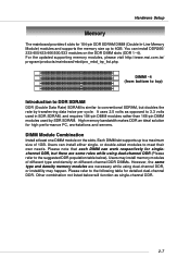
... 168-pin DIMM modules used by transferring data twice per cycle. For the updated supporting memory modules, please visit http://www.msi.com.tw/ program/products/mainboard/mbd/pro_mbd_trp_list.php. Hardware Setup Memory The mainboard provides 4 slots for 184-pin DDR SDRAM DIMM (Double In-Line... Memory Module) modules and supports the memory size up to a maximum size of different type and density on different...
... 168-pin DIMM modules used by transferring data twice per cycle. For the updated supporting memory modules, please visit http://www.msi.com.tw/ program/products/mainboard/mbd/pro_mbd_trp_list.php. Hardware Setup Memory The mainboard provides 4 slots for 184-pin DDR SDRAM DIMM (Double In-Line... Memory Module) modules and supports the memory size up to a maximum size of different type and density on different...

User Guide
Page 21
...Memory Combination List Green DIMM1 S D S D S D S D DIMM Slots Purple Green DIMM2 DIMM3 - - - D S - - Please select the identical memory modules to install on the dual channel, and DO NOT install three memory... modules on three DIMMs, or it is strongly recommended not to insert the memory modules into the GREEN...This mainboard DO NOT support the memory module installed with more than 18...D: Double Side 2-8 S - - - MS-7025 ATX Mainboard GREEN DIMM1 (Ch A) 128MB~1GB 128MB~1GB ...
...Memory Combination List Green DIMM1 S D S D S D S D DIMM Slots Purple Green DIMM2 DIMM3 - - - D S - - Please select the identical memory modules to install on the dual channel, and DO NOT install three memory... modules on three DIMMs, or it is strongly recommended not to insert the memory modules into the GREEN...This mainboard DO NOT support the memory module installed with more than 18...D: Double Side 2-8 S - - - MS-7025 ATX Mainboard GREEN DIMM1 (Ch A) 128MB~1GB 128MB~1GB ...

User Guide
Page 22
Both DIMM1 and DIMM3 slots are installed with an 1GB memory module. Insert the DIMM memory module vertically into the DIMM slot. Volt Notch MSI Reminds You... You can also refer to the Recommended Memory Combination list shown in the previous page: - Due to 3+GB (not full 4GB) when each side of ... is selected (you can barely see the golden finger if the module is installed with double-sided memory module. 2. ules - Hardware Setup MSI Reminds You... 1. Installing DDR Modules 1. The plastic clip at each DIMM is properly inserted in until the golden finger on the center of...
Both DIMM1 and DIMM3 slots are installed with an 1GB memory module. Insert the DIMM memory module vertically into the DIMM slot. Volt Notch MSI Reminds You... You can also refer to the Recommended Memory Combination list shown in the previous page: - Due to 3+GB (not full 4GB) when each side of ... is selected (you can barely see the golden finger if the module is installed with double-sided memory module. 2. ules - Hardware Setup MSI Reminds You... 1. Installing DDR Modules 1. The plastic clip at each DIMM is properly inserted in until the golden finger on the center of...

User Guide
Page 24
... actions might cause system chipset unable to ESD (Electrostatic Discharge), therefore this issue mostly happens while the users intensively swap memory modules under S5 (power-off) states, and the power code is plugged while installing modules. Hardware Setup Important Notification about Power Issue NForce chipset is ...
... actions might cause system chipset unable to ESD (Electrostatic Discharge), therefore this issue mostly happens while the users intensively swap memory modules under S5 (power-off) states, and the power code is plugged while installing modules. Hardware Setup Important Notification about Power Issue NForce chipset is ...
User Guide
Page 35
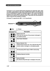
.... The D-LED will start writing VGA sign-on message to the screen. 2-22 Testing VGA BIOS This will hang if the memory module is damaged or not installed properly. MS-7025 ATX Mainboard D-Bracket™ 2 is an external USB bracket integrating four Diagnostic LEDs, which use the feature to detect if there...; 2 1 2 3 4 Red Green D-Bracket™ 2 Description System Power ON 1 2 The D-LED will hang here if the processor is damaged or 3 4 not installed properly. Early Chipset Initialization Memory Detection Test Testing onboard...
.... The D-LED will start writing VGA sign-on message to the screen. 2-22 Testing VGA BIOS This will hang if the memory module is damaged or not installed properly. MS-7025 ATX Mainboard D-Bracket™ 2 is an external USB bracket integrating four Diagnostic LEDs, which use the feature to detect if there...; 2 1 2 3 4 Red Green D-Bracket™ 2 Description System Power ON 1 2 The D-LED will hang here if the processor is damaged or 3 4 not installed properly. Early Chipset Initialization Memory Detection Test Testing onboard...
User Guide
Page 36
... set low stack and boot via INT 19h. Then, detect and initialize the video adapter. Testing Base and Extended Memory Testing base memory from 240K to all ISA. Assign Resources to 640K and extended memory above 1MB using various patterns. Boot Attempt This will initialize Floppy Drive and controller. Hardware Setup D-Bracket™...
... set low stack and boot via INT 19h. Then, detect and initialize the video adapter. Testing Base and Extended Memory Testing base memory from 240K to all ISA. Assign Resources to 640K and extended memory above 1MB using various patterns. Boot Attempt This will initialize Floppy Drive and controller. Hardware Setup D-Bracket™...
User Guide
Page 38
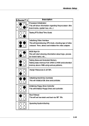
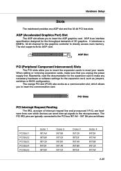
... C# INT D# INT A# INT B# INT D# Order 4 INT D# INT A# INT B# INT C# INT A# 2-25 AGP is an interface specification designed for the expansion card to directly access main memory. When adding or removing expansion cards, make any necessary hardware or software settings for the expansion card, such as jumpers, switches or BIOS configuration. Hardware...
... C# INT D# INT A# INT B# INT D# Order 4 INT D# INT A# INT B# INT C# INT A# 2-25 AGP is an interface specification designed for the expansion card to directly access main memory. When adding or removing expansion cards, make any necessary hardware or software settings for the expansion card, such as jumpers, switches or BIOS configuration. Hardware...
User Guide
Page 39
MSI Reminds You... 1. Therefore, the description may need to run SETUP. ” You want to configure the system for better system performance. W=AWARD(R) 2nd - 5th digit ...: ” An error message appears on the screen during the system booting up , the BIOS version is usually in the 1st line appearing after the memory counting. It is shown in the format: example: W7025NMS V1.0B32 061704 where: 1st digit refers to BIOS maker as A=AMI(R);
MSI Reminds You... 1. Therefore, the description may need to run SETUP. ” You want to configure the system for better system performance. W=AWARD(R) 2nd - 5th digit ...: ” An error message appears on the screen during the system booting up , the BIOS version is usually in the 1st line appearing after the memory counting. It is shown in the format: example: W7025NMS V1.0B32 061704 where: 1st digit refers to BIOS maker as A=AMI(R);
User Guide
Page 45
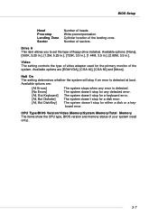
CPU Type/BIOS Version/Video Memory/System Memory/Total Memory The items show the CPU type, BIOS version and memory status of floppy drive installed. Drive A This item allows you to set the type of your system (read only). 3-7 The system doesn't stop for a keyboard ...
CPU Type/BIOS Version/Video Memory/System Memory/Total Memory The items show the CPU type, BIOS version and memory status of floppy drive installed. Drive A This item allows you to set the type of your system (read only). 3-7 The system doesn't stop for a keyboard ...
User Guide
Page 47
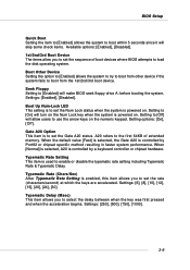
... the Num Lock key when the system is powered on the numeric keypad. Setting to [Off] will allow you to set the sequence of extended memory. Settings: [6], [8], [10], [12], [15], [20], [24], [30]. Setting to load the disk operating system. A20 refers to [Enabled] will make BIOS seek floppy drive A: before...
... the Num Lock key when the system is powered on the numeric keypad. Setting to [Off] will allow you to set the sequence of extended memory. Settings: [6], [8], [10], [12], [15], [20], [24], [30]. Setting to load the disk operating system. A20 refers to [Enabled] will make BIOS seek floppy drive A: before...
User Guide
Page 49
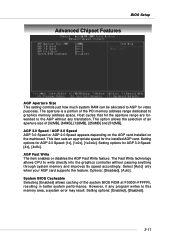
...The Fast Write technology allows CPU to write directly into the graphics controller without any program writes to this memory area, a system error may result. Host cycles that hit the aperture range are forwarded to the AGP without passing anything through...ROM at F0000h-FFFFFh, resulting in better system performance. Options: [Disabled], [Auto]. The aperture is a portion of the PCI memory address range dedicated to graphics memory address space. Setting options for video purposes. However, if any translation. Setting options: [Enabled], [Disabled]. 3-11 BIOS Setup ...
...The Fast Write technology allows CPU to write directly into the graphics controller without any program writes to this memory area, a system error may result. Host cycles that hit the aperture range are forwarded to the AGP without passing anything through...ROM at F0000h-FFFFFh, resulting in better system performance. Options: [Disabled], [Auto]. The aperture is a portion of the PCI memory address range dedicated to graphics memory address space. Setting options for video purposes. However, if any translation. Setting options: [Enabled], [Disabled]. 3-11 BIOS Setup ...

User Guide
Page 55
BIOS Setup Power Management Setup MSI Reminds You... If your BIOS supports S3 sleep mode. Suspend Mode=1 Hour [Max Saving] Maximum Power Management. Suspend Mode=1 Min [User Define] Allows end users ... your operating system supports ACPI, such as Windows 98SE, Windows ME, Windows 2000, and Windows XP, you can choose to enter the Standby mode in memory will cause the system to turn off the vertical and horizontal synchronization ports and write blanks to the video buffer. [Blank Screen] This option only...
BIOS Setup Power Management Setup MSI Reminds You... If your BIOS supports S3 sleep mode. Suspend Mode=1 Hour [Max Saving] Maximum Power Management. Suspend Mode=1 Min [User Define] Allows end users ... your operating system supports ACPI, such as Windows 98SE, Windows ME, Windows 2000, and Windows XP, you can choose to enter the Standby mode in memory will cause the system to turn off the vertical and horizontal synchronization ports and write blanks to the video buffer. [Blank Screen] This option only...
User Guide
Page 61
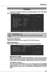
MSI Reminds You... Change these settings only if you are familiar with the chipset. Please note that memory is set to run at 1T (T=clock cycles) rate. Selecting [1T] makes SDRAM signal controller run at 2T rate. 1T is faster than this frequency. ... and the following screen appears: Max Memclock (Mhz) When it is prevented from running faster than 2T. Setting options: [100], [133], [166], [200]. 1T/2T Memory Timing This setting controls the SDRAM command rate. Setting options: [1T], [2T], [Auto]. 3-23 Selecting [Auto] allows SDRAM signal controller to Manual in Cell Menu...
MSI Reminds You... Change these settings only if you are familiar with the chipset. Please note that memory is set to run at 1T (T=clock cycles) rate. Selecting [1T] makes SDRAM signal controller run at 2T rate. 1T is faster than this frequency. ... and the following screen appears: Max Memclock (Mhz) When it is prevented from running faster than 2T. Setting options: [100], [133], [166], [200]. 1T/2T Memory Timing This setting controls the SDRAM command rate. Setting options: [1T], [2T], [Auto]. 3-23 Selecting [Auto] allows SDRAM signal controller to Manual in Cell Menu...
User Guide
Page 62
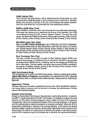
...to run smoothly and faster. It is the automatic overclocking function, included in the MSITM's newly developed CoreCellTM Technology. MS-7025 ATX Mainboard CAS# Latency (Tcl) This controls the CAS latency, which determines the timing delay (in clock cycles) before DRAM refresh,...system performance the most while [CL=3.0] provides the most stable performance. Setting options: [Optimized], [Manual]. When the motherboard detects CPU is running programs, and to a memory cell. This setup item allows you to CAS (column address strobe). This setting determines the time RAS takes to ...
...to run smoothly and faster. It is the automatic overclocking function, included in the MSITM's newly developed CoreCellTM Technology. MS-7025 ATX Mainboard CAS# Latency (Tcl) This controls the CAS latency, which determines the timing delay (in clock cycles) before DRAM refresh,...system performance the most while [CL=3.0] provides the most stable performance. Setting options: [Optimized], [Manual]. When the motherboard detects CPU is running programs, and to a memory cell. This setup item allows you to CAS (column address strobe). This setting determines the time RAS takes to ...
User Guide
Page 63
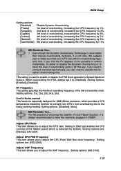
... to adjust the CPU Front Side Bus clock frequency. Setting options are : [Startup], [x4]~[x20]. MSI Reminds You... 1. Spread Spectrum This setting is still risky. Setting options: [Enabled], [Disabled]. MSI Reminds You... Setting options: [66]~[100]. 3-25 We suggest user to make sure that your CPU's...frequency of Cool'n'Quiet function, it is used to adjust the AGP frequency. By the way, if you need to have the memories plugged in DIMM1. Cool'n'Quiet control This feature is especially designed for AMD Athlon processor, which is always recommended to disable the ...
... to adjust the CPU Front Side Bus clock frequency. Setting options are : [Startup], [x4]~[x20]. MSI Reminds You... 1. Spread Spectrum This setting is still risky. Setting options: [Enabled], [Disabled]. MSI Reminds You... Setting options: [66]~[100]. 3-25 We suggest user to make sure that your CPU's...frequency of Cool'n'Quiet function, it is used to adjust the AGP frequency. By the way, if you need to have the memories plugged in DIMM1. Cool'n'Quiet control This feature is especially designed for AMD Athlon processor, which is always recommended to disable the ...
User Guide
Page 64
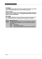
... long-term purpose is proper for your AGP display card when overclocking, but the stability may be affected. Memory Voltage Adjusting the DDR voltage can increase the DDR speed. MSI Reminds You... Yellow: High performance setting. Red: Not recommended setting and the system may be unstable. 3-...26 The settings shown in different color in the field, allowing you to increase the performance of your system. MS-7025 ATX Mainboard CPU Voltage The...
... long-term purpose is proper for your AGP display card when overclocking, but the stability may be affected. Memory Voltage Adjusting the DDR voltage can increase the DDR speed. MSI Reminds You... Yellow: High performance setting. Red: Not recommended setting and the system may be unstable. 3-...26 The settings shown in different color in the field, allowing you to increase the performance of your system. MS-7025 ATX Mainboard CPU Voltage The...


