User Guide
Page 4
... are for technical guide, BIOS updates, driver updates, and other information: http://www.msi.com.tw & http://www.msi. iv If any of breakage. 12. fore connecting the equipment to moisture. † The equipment has not work according to User's Manual. † The...Replace only with your place of the power source and adjust properly 110/220V be noted. 10. Make sure the voltage of purchase or local distributor. Technical Support If a problem arises with the same or equivalent type recommended by a service personnel: † The power cord or plug is incorrectly replaced...
... are for technical guide, BIOS updates, driver updates, and other information: http://www.msi.com.tw & http://www.msi. iv If any of breakage. 12. fore connecting the equipment to moisture. † The equipment has not work according to User's Manual. † The...Replace only with your place of the power source and adjust properly 110/220V be noted. 10. Make sure the voltage of purchase or local distributor. Technical Support If a problem arises with the same or equivalent type recommended by a service personnel: † The power cord or plug is incorrectly replaced...
User Guide
Page 5
Getting Started E-1-3 2. Hardware Setup E-2-1 3. BIOS Setup ...E-3-1 Français ...F-1 Deutsch ...G-1 v CONTENTS FCC-B Radio Frequency Interference Statement ii Copyright Notice ...iii Revision History ...iii Technical Support ...iv Safety Instructions ...iv English ...E-1-1 1.
Getting Started E-1-3 2. Hardware Setup E-2-1 3. BIOS Setup ...E-3-1 Français ...F-1 Deutsch ...G-1 v CONTENTS FCC-B Radio Frequency Interference Statement ii Copyright Notice ...iii Revision History ...iii Technical Support ...iv Safety Instructions ...iv English ...E-1-1 1.

User Guide
Page 9
... SATA Interface Main Memory † Supports six memory banks dual channel DDR, using three 184-pin DDR DIMMs † Supports a maximum memory size up to four IDE devices E-1-4 Integrated graphics controller (IGP only) † NVIDIA nForce2 Gigabit MCP/RAID MCP - Supports USB 2.0 - Ultra DMA 66/100/133 master mode PCI EIDE controller - AGP 8X and PCI Advanced high performance memory controller - Controlled by Gigabit MCP/RAID MCP southbridge - 4 ports in the rear I/O, 4 ports via external bracket On-Board IDE † Two IDE controllers integrated...
... SATA Interface Main Memory † Supports six memory banks dual channel DDR, using three 184-pin DDR DIMMs † Supports a maximum memory size up to four IDE devices E-1-4 Integrated graphics controller (IGP only) † NVIDIA nForce2 Gigabit MCP/RAID MCP - Supports USB 2.0 - Ultra DMA 66/100/133 master mode PCI EIDE controller - AGP 8X and PCI Advanced high performance memory controller - Controlled by Gigabit MCP/RAID MCP southbridge - 4 ports in the rear I/O, 4 ports via external bracket On-Board IDE † Two IDE controllers integrated...

User Guide
Page 10
... 2 ports † One SATA controller, supporting two drives in master mode ATTENTION!!! Under these two OSs, SATA can only be used as a normal storage device. Digital SPDIF out signal compatible W/S-Bracket SATA Interface † Integrated SATA Phy, supporting up to 3 * 1394 ports (via external bracket). Please note that users cannot install OS, neither WinME nor Win98, in vertical - 1 D-Bracket2 pinheader † On-Board 10/100/1000 (Optional) Ethernet - Getting Started On-Board...
... 2 ports † One SATA controller, supporting two drives in master mode ATTENTION!!! Under these two OSs, SATA can only be used as a normal storage device. Digital SPDIF out signal compatible W/S-Bracket SATA Interface † Integrated SATA Phy, supporting up to 3 * 1394 ports (via external bracket). Please note that users cannot install OS, neither WinME nor Win98, in vertical - 1 D-Bracket2 pinheader † On-Board 10/100/1000 (Optional) Ethernet - Getting Started On-Board...

User Guide
Page 11
... "Plug & Play" BIOS which detects the peripheral devices and expansion cards of the board automatically. † The mainboard provides a Desktop Management Interface (DMI) function which records your mainboard specifications. To create a bootable RAID volume for a Windows 2000 environment, Microsoft's Windows 2000 Service Pack 4 (SP4) is supported - RAID 0, or 1, 0+1, JBOD is required. To create the combination installation CD, please refer to RAM/Disk (S3/S4) † Supports PCI 2.3 ATTENTION!!! Dimension † ATX...
... "Plug & Play" BIOS which detects the peripheral devices and expansion cards of the board automatically. † The mainboard provides a Desktop Management Interface (DMI) function which records your mainboard specifications. To create a bootable RAID volume for a Windows 2000 environment, Microsoft's Windows 2000 Service Pack 4 (SP4) is supported - RAID 0, or 1, 0+1, JBOD is required. To create the combination installation CD, please refer to RAM/Disk (S3/S4) † Supports PCI 2.3 ATTENTION!!! Dimension † ATX...
User Guide
Page 12
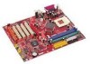
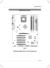
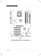
... ATX Power Supply Top : Parallel Port Bottom: COM A VGA (Optional) C _FA N 1 T: SPDIF Out B: USB ports T: LAN jack B: USB ports T:Line-In M:Line-Out B:Mic J PW1 nVIDIA nFORCE2 Ultra 400/ IGP NB_ FA N1 DIMM 1 DIMM 2 DIMM 3 RT L8 2 0 1 B L/ CL Code c AGP Slot S_ FAN2 PCI Slot 1 PCI Slot 2 PCI Slot 3 PCI Slot 4 PCI Slot 5 J1394_1 (optional) NVIDIA nFORCE2 Gigabit MCP/ RAID MCP SATA1 SATA2 VIA VT6306 (optional) J1394_2 (optional) J1394_3 (optional) JUSB1 JLED1 BIOS JUSB2 JFP1 JFP2 JIR1 Type I JCD1 JAUD1 K7N2 Delta2...
... ATX Power Supply Top : Parallel Port Bottom: COM A VGA (Optional) C _FA N 1 T: SPDIF Out B: USB ports T: LAN jack B: USB ports T:Line-In M:Line-Out B:Mic J PW1 nVIDIA nFORCE2 Ultra 400/ IGP NB_ FA N1 DIMM 1 DIMM 2 DIMM 3 RT L8 2 0 1 B L/ CL Code c AGP Slot S_ FAN2 PCI Slot 1 PCI Slot 2 PCI Slot 3 PCI Slot 4 PCI Slot 5 J1394_1 (optional) NVIDIA nFORCE2 Gigabit MCP/ RAID MCP SATA1 SATA2 VIA VT6306 (optional) J1394_2 (optional) J1394_3 (optional) JUSB1 JLED1 BIOS JUSB2 JFP1 JFP2 JIR1 Type I JCD1 JAUD1 K7N2 Delta2...
User Guide
Page 13
... d ec PCI Slot 1 PCI Slot 2 PCI Slot 3 PCI Slot 4 PCI Slot 5 J1394_1 (optional) NVIDIA nFORCE2 Gigabit MCP/ RAID MCP SATA1 SATA2 VIA VT6306 (optional) J1394_2 (optional) J1394_3 (optional) JUSB1 JLED1 BIOS JUSB2 JFP1 JFP2 JIR1 JC D1 JAUD1 Type II K7N2 Delta2 (MS-6570E v1.X) Series Mainboard IDE 2 IDE 1 JBAT 1 B ATT + S_FA N1 E-1-8 JCI1 W i n b on d W 83627TH F FDD 1 MS-6570E ATX Mainboard Top : mouse Bottom: keyboard SOCKET 462 AT X Power S upply Top : Parallel Port Bottom: COM A VGA (Optional) C_ FA N 1 T: SPDIF Out B: USB ports T: LAN jack B: USB ports...
... d ec PCI Slot 1 PCI Slot 2 PCI Slot 3 PCI Slot 4 PCI Slot 5 J1394_1 (optional) NVIDIA nFORCE2 Gigabit MCP/ RAID MCP SATA1 SATA2 VIA VT6306 (optional) J1394_2 (optional) J1394_3 (optional) JUSB1 JLED1 BIOS JUSB2 JFP1 JFP2 JIR1 JC D1 JAUD1 Type II K7N2 Delta2 (MS-6570E v1.X) Series Mainboard IDE 2 IDE 1 JBAT 1 B ATT + S_FA N1 E-1-8 JCI1 W i n b on d W 83627TH F FDD 1 MS-6570E ATX Mainboard Top : mouse Bottom: keyboard SOCKET 462 AT X Power S upply Top : Parallel Port Bottom: COM A VGA (Optional) C_ FA N 1 T: SPDIF Out B: USB ports T: LAN jack B: USB ports...

User Guide
Page 17
... by Core/Bus ratio equals the CPU core speed. For the latest information about CPU, please visit http://www.msi.com.tw/ program/products/mainboard/mbd/pro_mbd_cpu_support.php. Replacing the CPU While replacing the CPU, always turn off the ATX power supply or unplug the power supply's power cord from overheating. CPU Core Speed Derivation Procedure CPU Clock multiplied by inadequate operation or beyond product specifications is not recommended. Hardware Setup Central Processing Unit: CPU The mainboard supports AMD®...
... by Core/Bus ratio equals the CPU core speed. For the latest information about CPU, please visit http://www.msi.com.tw/ program/products/mainboard/mbd/pro_mbd_cpu_support.php. Replacing the CPU While replacing the CPU, always turn off the ATX power supply or unplug the power supply's power cord from overheating. CPU Core Speed Derivation Procedure CPU Clock multiplied by inadequate operation or beyond product specifications is not recommended. Hardware Setup Central Processing Unit: CPU The mainboard supports AMD®...

User Guide
Page 19
... CPU cooler set . 1. Position your agent for the proper CPU cooler set onto the CPU. 2. Apply some heat sink paste on your mainboard. Connect the fan to dissipate the heat more effectively. Use one end of the clip to hook the latch of CPU to the power supply connector provided on top of the CPU sliding plate. 3. Hardware Setup Installing AMD Athlon CPU (Socket 462) Cooler Set The following instructions will guide...
... CPU cooler set . 1. Position your agent for the proper CPU cooler set onto the CPU. 2. Apply some heat sink paste on your mainboard. Connect the fan to dissipate the heat more effectively. Use one end of the clip to hook the latch of CPU to the power supply connector provided on top of the CPU sliding plate. 3. Hardware Setup Installing AMD Athlon CPU (Socket 462) Cooler Set The following instructions will guide...

User Guide
Page 20
... Side E-2-6 MS-6570E ATX Mainboard Memory The mainboard provides 3 slots for 184-pin DDR SDRAM DIMM (Double InLine Memory Module) modules and supports the memory size up to meet your own needs. Please note that the system will support dual channel DDR when you install DDR modules on the slots. For the updated supporting memory modules, please visit http://www.msi. DDR 1 DDR 2 DDR 3 Memory Speed/CPU FSB Support Matrix Memory CPU FSB 133MHz 166MHz...
... Side E-2-6 MS-6570E ATX Mainboard Memory The mainboard provides 3 slots for 184-pin DDR SDRAM DIMM (Double InLine Memory Module) modules and supports the memory size up to meet your own needs. Please note that the system will support dual channel DDR when you install DDR modules on the slots. For the updated supporting memory modules, please visit http://www.msi. DDR 1 DDR 2 DDR 3 Memory Speed/CPU FSB Support Matrix Memory CPU FSB 133MHz 166MHz...

User Guide
Page 22
... the ATX power supply and have to work together to an ATX power supply. To connect to the ATX power supply, make sure that no damage will be caused. Then push down the power supply firmly into the connector. E-2-8 ATX 20-Pin Power Connector: JWR1 This connector allows you to connect to ensure stable operation of 300 watts (and above) is highly recommended for the power system. Power supply of the mainboard. 2. MS-6570E ATX Mainboard Power Supply The mainboard supports ATX power supply...
... the ATX power supply and have to work together to an ATX power supply. To connect to the ATX power supply, make sure that no damage will be caused. Then push down the power supply firmly into the connector. E-2-8 ATX 20-Pin Power Connector: JWR1 This connector allows you to connect to ensure stable operation of 300 watts (and above) is highly recommended for the power system. Power supply of the mainboard. 2. MS-6570E ATX Mainboard Power Supply The mainboard supports ATX power supply...

User Guide
Page 29
... CPU cooling fan. 2. Floppy Disk Drive Connector: FDD1 The mainboard provides a standard floppy disk drive connector that the red wire is the positive and should be connected to the +12V, the black wire is Ground and should be connected to the connectors, always take advantage of the CPU fan control. Hardware Setup Connectors The mainboard provides connectors to connect to the recommended CPU fans at AMD® official website. If the mainboard has a System Hardware Monitor chipset on-board, you must use...
... CPU cooling fan. 2. Floppy Disk Drive Connector: FDD1 The mainboard provides a standard floppy disk drive connector that the red wire is the positive and should be connected to the +12V, the black wire is Ground and should be connected to the connectors, always take advantage of the CPU fan control. Hardware Setup Connectors The mainboard provides connectors to connect to the recommended CPU fans at AMD® official website. If the mainboard has a System Hardware Monitor chipset on-board, you must use...

User Guide
Page 31
... connectors are dual high-speed Serial ATA interface ports. SATA1 1 7 SATA2 7 1 Serial ATA cable SATA1/SATA2 Pin Definition PIN SIGNAL 1 GND 3 TXN 5 RXN 7 GND PIN SIGNAL 2 TXP 4 GND 6 RXP Connect to serial ATA ports Take out the dust cover and connect to 1 hard disk device. Hardware Setup Serial ATA RAID Connectors controlled by nForce2 RAID MCP: SATA1/SATA2 The Southbridge of 150 MB/s. SATA1 and SATA2 are fully compliant with Serial ATA 1.0 specifications. E-2-17 Each Serial ATA connector...
... connectors are dual high-speed Serial ATA interface ports. SATA1 1 7 SATA2 7 1 Serial ATA cable SATA1/SATA2 Pin Definition PIN SIGNAL 1 GND 3 TXN 5 RXN 7 GND PIN SIGNAL 2 TXP 4 GND 6 RXP Connect to serial ATA ports Take out the dust cover and connect to 1 hard disk device. Hardware Setup Serial ATA RAID Connectors controlled by nForce2 RAID MCP: SATA1/SATA2 The Southbridge of 150 MB/s. SATA1 and SATA2 are fully compliant with Serial ATA 1.0 specifications. E-2-17 Each Serial ATA connector...

User Guide
Page 33
... front panel audio and is for future use to control headphone amplifier 8 KEY No pin 9 AUD_FPOUT_L Left channel audio signal to the rear audio ports. JAUD1 2 10 1 9 Pin Definition PIN SIGNAL DESCRIPTION 1 AUD_MIC Front panel microphone input signal 2 AUD_GND Ground used by analog audio circuits 3 AUD_MIC_BIAS Microphone power 4 AUD_VCC Filtered +5V used by analog audio circuits 5 AUD_FPOUT_R Right channel audio signal to front panel 6 AUD_RET_R Right channel audio signal return from front panel MSI Reminds...
... front panel audio and is for future use to control headphone amplifier 8 KEY No pin 9 AUD_FPOUT_L Left channel audio signal to the rear audio ports. JAUD1 2 10 1 9 Pin Definition PIN SIGNAL DESCRIPTION 1 AUD_MIC Front panel microphone input signal 2 AUD_GND Ground used by analog audio circuits 3 AUD_MIC_BIAS Microphone power 4 AUD_VCC Filtered +5V used by analog audio circuits 5 AUD_FPOUT_R Right channel audio signal to front panel 6 AUD_RET_R Right channel audio signal return from front panel MSI Reminds...

User Guide
Page 36
...; 2 Connector: JLED1 The mainboard comes with Intel® Front Panel I/O Connectivity Design Guide. D-Bracket™ 2 is compliant with a JLED1 connector for red color) 9 Key 10 NC Connected to JLED1 Connected to use the IR function. You must configure the setting through 16 various combinations of LED signals. IrDA Infrared Module Header: JIR1 The connector allows you to connect to IrDA Infrared module. JLED1 Pin Definition Pin Signal 1 DBG1 (high...
...; 2 Connector: JLED1 The mainboard comes with Intel® Front Panel I/O Connectivity Design Guide. D-Bracket™ 2 is compliant with a JLED1 connector for red color) 9 Key 10 NC Connected to JLED1 Connected to use the IR function. You must configure the setting through 16 various combinations of LED signals. IrDA Infrared Module Header: JIR1 The connector allows you to connect to IrDA Infrared module. JLED1 Pin Definition Pin Signal 1 DBG1 (high...

User Guide
Page 37
.... Clear CMOS Jumper: JBAT1 There is off. Then return to set the computer's function. Avoid clearing the CMOS while the system is turned on. Hardware Setup Jumpers The motherboard provides the following jumpers for you want to clear the system configuration, use of jumpers. Follow the instructions below to change your motherboard's function through the use the JBAT1 (Clear CMOS Jumper ) to keep the system configuration data. With the CMOS RAM, the system can clear CMOS by shorting 2-3 pin...
.... Clear CMOS Jumper: JBAT1 There is off. Then return to set the computer's function. Avoid clearing the CMOS while the system is turned on. Hardware Setup Jumpers The motherboard provides the following jumpers for you want to clear the system configuration, use of jumpers. Follow the instructions below to change your motherboard's function through the use the JBAT1 (Clear CMOS Jumper ) to keep the system configuration data. With the CMOS RAM, the system can clear CMOS by shorting 2-3 pin...
User Guide
Page 38
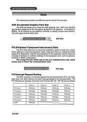
... The PCI IRQ pins are hardware lines over which allows you to insert the expansion cards to insert the communication card. MS-6570E ATX Mainboard Slots The mainboard provides one AGP slot and five 32-bit PCI bus slots. The slot supports 8x/4x AGP card. AGP (Accelerated Graphics Port) Slot The AGP slot allows you unplug the power supply first. AGP is an interface specification designed for the expansion card, such as jumpers, switches or BIOS configuration. PCI Slots PCI...
... The PCI IRQ pins are hardware lines over which allows you to insert the expansion cards to insert the communication card. MS-6570E ATX Mainboard Slots The mainboard provides one AGP slot and five 32-bit PCI bus slots. The slot supports 8x/4x AGP card. AGP (Accelerated Graphics Port) Slot The AGP slot allows you unplug the power supply first. AGP is an interface specification designed for the expansion card, such as jumpers, switches or BIOS configuration. PCI Slots PCI...

User Guide
Page 43
.... Change these settings only if you are familiar with the chipset. When E-3-5 It is the automatic overclocking function, included in Cell Menu includes some important settings of the installed DRAMs. (read only) High Performance Mode This field allows users to adjust the best CPU frequency automatically. BIOS Setup Cell Menu The items in the MSITM's newly developed CoreCellTM Technology. Current CPU Clock It shows the current CPU clock frequency. (Read-only) Current DRAM Clock...
.... Change these settings only if you are familiar with the chipset. When E-3-5 It is the automatic overclocking function, included in Cell Menu includes some important settings of the installed DRAMs. (read only) High Performance Mode This field allows users to adjust the best CPU frequency automatically. BIOS Setup Cell Menu The items in the MSITM's newly developed CoreCellTM Technology. Current CPU Clock It shows the current CPU clock frequency. (Read-only) Current DRAM Clock...
User Guide
Page 45
... allowed to the external or motherboard clock speed. When [Aggressive] is controlled by BIOS based on the configurations on the DRAM module. Please note that is used to determine the internal clock speed of clock cycles for the most stable CPU/FSB parameters. This item applies only when synchronous DRAM is installed in the system. T-(RAS) This setting controls the number of the processor relative to precharge from...
... allowed to the external or motherboard clock speed. When [Aggressive] is controlled by BIOS based on the configurations on the DRAM module. Please note that is used to determine the internal clock speed of clock cycles for the most stable CPU/FSB parameters. This item applies only when synchronous DRAM is installed in the system. T-(RAS) This setting controls the number of the processor relative to precharge from...

User Guide
Page 46
... overclocking the AGP slot, always set it to set to enable or disable the FSB clock generator's Spread Specturm feature. Options: [Disabled], [0.50%]. FSB Spread Spectrum This item is set the AGP clock manually or by default. AGP Clock Value W hen AGP Clock Control is used to [Disabled]. When overclocking the FSB, always set it to enable or disable the AGP clock generator's Spread Specturm feature. Options: [Default], [Manual]. MS-6570E ATX Mainboard AGP Clock Control This item allows users to [Disabled]. Options: [Disabled...
... overclocking the AGP slot, always set it to set to enable or disable the FSB clock generator's Spread Specturm feature. Options: [Disabled], [0.50%]. FSB Spread Spectrum This item is set the AGP clock manually or by default. AGP Clock Value W hen AGP Clock Control is used to [Disabled]. When overclocking the FSB, always set it to enable or disable the AGP clock generator's Spread Specturm feature. Options: [Default], [Manual]. MS-6570E ATX Mainboard AGP Clock Control This item allows users to [Disabled]. Options: [Disabled...


