
User Guide
Page 2
...2009 Technical Support If a problem arises with your system and no guarantee is given as to make changes without notice. Visit the MSI website at http://ocss.msi.com.tw. ii Copyright Notice The material in this document, but no solution can be obtained from the user's manual, please...information. Intel® and Pentium® are registered trademarks of Intel Corporation. Alternatively, please try the following help resources for FAQ, technical guide, BIOS updates, driver updates, and other countries. AMD, Athlon™, Athlon™ XP, Thoroughbred™, and Duron™ are ...
...2009 Technical Support If a problem arises with your system and no guarantee is given as to make changes without notice. Visit the MSI website at http://ocss.msi.com.tw. ii Copyright Notice The material in this document, but no solution can be obtained from the user's manual, please...information. Intel® and Pentium® are registered trademarks of Intel Corporation. Alternatively, please try the following help resources for FAQ, technical guide, BIOS updates, driver updates, and other countries. AMD, Athlon™, Athlon™ XP, Thoroughbred™, and Duron™ are ...

User Guide
Page 3
Safety Instructions 1. The openings on card or module. 9. Place the power cord such a way that could damage or cause electrical s h oc k . 11. Always Unplug the Power Cord before setting it . The equipment has been exposed to the power inlet. 7. The equipment has obvious sign of the following situations arises, get it work well or you can not step on the equipment...
Safety Instructions 1. The openings on card or module. 9. Place the power cord such a way that could damage or cause electrical s h oc k . 11. Always Unplug the Power Cord before setting it . The equipment has been exposed to the power inlet. 7. The equipment has obvious sign of the following situations arises, get it work well or you can not step on the equipment...

User Guide
Page 4
... user's authority to provide reasonable protection against harmful interference in a residential installation. Notice 2 Shielded interface cables and A.C. Micro-Star International MS-9830 This device complies with Part 15 of the FCC Rules. This equipment generates, uses and can be used in accordance with the instructions, may cause harmful interference to the following two conditions: (1) this device must be determined by turning...
... user's authority to provide reasonable protection against harmful interference in a residential installation. Notice 2 Shielded interface cables and A.C. Micro-Star International MS-9830 This device complies with Part 15 of the FCC Rules. This equipment generates, uses and can be used in accordance with the instructions, may cause harmful interference to the following two conditions: (1) this device must be determined by turning...

User Guide
Page 8
... Trademarks ...ii Revision History ...ii Technical Support ...ii Safety Instructions ...iii FCC-B Radio Frequency Interference Statement iv W EEE (Waste Electrical and Electronic Equipment) Statement v Chapter 1 Product Overview 1-1 Mainboard Specifications 1-2 Block Diagram ...1-5 Mainboard Layout 1-6 Board Dimension 1-11 Back Panel & I/O Shield Drawing 1-12 Power Consumption 1-17 Safety Compliance & MTBF 1-19 Chapter 2 Hardware Setup 2-1 Quick Components Guide 2-2 Memory ...2-3 Power Supply ...2-4 Back Panel I/O ...2-5 Connector ...2-11 Jumper ...2-19...
... Trademarks ...ii Revision History ...ii Technical Support ...ii Safety Instructions ...iii FCC-B Radio Frequency Interference Statement iv W EEE (Waste Electrical and Electronic Equipment) Statement v Chapter 1 Product Overview 1-1 Mainboard Specifications 1-2 Block Diagram ...1-5 Mainboard Layout 1-6 Board Dimension 1-11 Back Panel & I/O Shield Drawing 1-12 Power Consumption 1-17 Safety Compliance & MTBF 1-19 Chapter 2 Hardware Setup 2-1 Quick Components Guide 2-2 Memory ...2-3 Power Supply ...2-4 Back Panel I/O ...2-5 Connector ...2-11 Jumper ...2-19...

User Guide
Page 33
...-232 Serial Port VGA Port LAN Hardware Setup Line-In Line-Out LAN COM5 RS-232/422/485 Serial Port DVI Port USB Ports USB Ports MIC Serial Port The serial port is a 16550A high speed communications port that the other end of the cable is properly connected to your monitor (refer to your monitor cable into the DVI connector, and make sure that sends/ receives 16 bytes FIFOs. DVI Port The DVI (Digital Visual Interface) connector allows you...
...-232 Serial Port VGA Port LAN Hardware Setup Line-In Line-Out LAN COM5 RS-232/422/485 Serial Port DVI Port USB Ports USB Ports MIC Serial Port The serial port is a 16550A high speed communications port that the other end of the cable is properly connected to your monitor (refer to your monitor cable into the DVI connector, and make sure that sends/ receives 16 bytes FIFOs. DVI Port The DVI (Digital Visual Interface) connector allows you...

User Guide
Page 35
...(Lighting) Orange(Lighting) OFF Audio Ports These audio connectors are used for different audio sound effects. You can differentiate the color of the cable is properly connected to your monitor (refer to your monitor cable into the DVI connector, and make sure that sends/ receives 16 bytes FIFOs. Option B Hardware Setup LAN Line-Out COM5 RS-232/422/485 Serial Port DVI Port USB Ports USB Ports MIC Serial Port The serial port...
...(Lighting) Orange(Lighting) OFF Audio Ports These audio connectors are used for different audio sound effects. You can differentiate the color of the cable is properly connected to your monitor (refer to your monitor cable into the DVI connector, and make sure that sends/ receives 16 bytes FIFOs. Option B Hardware Setup LAN Line-Out COM5 RS-232/422/485 Serial Port DVI Port USB Ports USB Ports MIC Serial Port The serial port...

User Guide
Page 36
... Blinking Green (Lighting) Right LED 100M/1000M Speed LED Green/Orange OFF OFF Green(Lighting) Green(Lighting) Orange(Lighting) Orange(Lighting) OFF Audio Ports These audio connectors are used for audio devices. You can attach a serial mouse or other USB-compatible devices. Mic (Pink) - Mic, is for connection to the Local Area Network (LAN). You can connect a network cable to it. MS-9830 Mainboard Option C LAN Line-Out COM5 RS-232/422/485 Serial Port VGA Port USB Ports USB Ports MIC Serial Port...
... Blinking Green (Lighting) Right LED 100M/1000M Speed LED Green/Orange OFF OFF Green(Lighting) Green(Lighting) Orange(Lighting) Orange(Lighting) OFF Audio Ports These audio connectors are used for audio devices. You can attach a serial mouse or other USB-compatible devices. Mic (Pink) - Mic, is for connection to the Local Area Network (LAN). You can connect a network cable to it. MS-9830 Mainboard Option C LAN Line-Out COM5 RS-232/422/485 Serial Port VGA Port USB Ports USB Ports MIC Serial Port...

User Guide
Page 37
... the DVI connector, and make sure that sends/ receives 16 bytes FIFOs. You can attach a serial mouse or other USB-compatible devices. Mic (Pink) - DVI Port The DVI (Digital Visual Interface) connector allows you to the Local Area Network (LAN). Option D VGA Port Hardware Setup LAN Line-Out COM5 RS-232/422/485 Serial Port DVI Port USB Ports USB Ports MIC Serial Port The serial port is a 16550A high speed communications port that the other end of the...
... the DVI connector, and make sure that sends/ receives 16 bytes FIFOs. You can attach a serial mouse or other USB-compatible devices. Mic (Pink) - DVI Port The DVI (Digital Visual Interface) connector allows you to the Local Area Network (LAN). Option D VGA Port Hardware Setup LAN Line-Out COM5 RS-232/422/485 Serial Port DVI Port USB Ports USB Ports MIC Serial Port The serial port is a 16550A high speed communications port that the other end of the...

User Guide
Page 38
... Cable Plug-in No Transmission Transition In S3/S4/S5 Standby State Left LED Active LED Yellow Slow Blinking Swiftly Blinking Slow Blinking Swiftly Blinking Slow Blinking Swiftly Blinking Green (Lighting) Right LED 100M/1000M Speed LED Green/Orange OFF OFF Green(Lighting) Green(Lighting) Orange(Lighting) Orange(Lighting) OFF Audio Ports These audio connectors are used for attaching USB devices such as keyboard, mouse, or other serial devices directly to the Local Area Network (LAN). Line...
... Cable Plug-in No Transmission Transition In S3/S4/S5 Standby State Left LED Active LED Yellow Slow Blinking Swiftly Blinking Slow Blinking Swiftly Blinking Slow Blinking Swiftly Blinking Green (Lighting) Right LED 100M/1000M Speed LED Green/Orange OFF OFF Green(Lighting) Green(Lighting) Orange(Lighting) Orange(Lighting) OFF Audio Ports These audio connectors are used for attaching USB devices such as keyboard, mouse, or other serial devices directly to the Local Area Network (LAN). Line...

User Guide
Page 39
Hardware Setup Connector IDE Connector: IDE1 This connector supports IDE hard disk drives, optical disk drives and other IDE devices. IDE1 Important If you install two IDE devices on the same cable, you must configure the drives separately to IDE device's documentation supplied by setting jumpers. Refer to master / slave mode by the vendors for jumper setting instructions. 2-11
Hardware Setup Connector IDE Connector: IDE1 This connector supports IDE hard disk drives, optical disk drives and other IDE devices. IDE1 Important If you install two IDE devices on the same cable, you must configure the drives separately to IDE device's documentation supplied by setting jumpers. Refer to master / slave mode by the vendors for jumper setting instructions. 2-11

User Guide
Page 43
... GND 22 GND 24 GND 26 KEY 2-15 Hardware Setup Serial Port Connector: COM1 ~ COM4 (for connection to it through the optional serial port bracket. COM1~4 1 2 9 10 Pin Definition PIN SIGNAL DESCRIPTION 1 DCD Data Carry Detect 2 SIN Serial In or Receive Data 3 SOUT Serial Out or Transmit Data 4 DTR Data Terminal Ready 5 GND Ground 6 DSR Data Set Ready 7 RTS Request To Send 8 CTS...
... GND 22 GND 24 GND 26 KEY 2-15 Hardware Setup Serial Port Connector: COM1 ~ COM4 (for connection to it through the optional serial port bracket. COM1~4 1 2 9 10 Pin Definition PIN SIGNAL DESCRIPTION 1 DCD Data Carry Detect 2 SIN Serial In or Receive Data 3 SOUT Serial Out or Transmit Data 4 DTR Data Terminal Ready 5 GND Ground 6 DSR Data Set Ready 7 RTS Request To Send 8 CTS...

User Guide
Page 48
... adding or removing expansion cards, make sure that you unplug the power supply first. MS-9830 Mainboard Slot PCI (Peripheral Component Interconnect) Express Slot The CON1 is Mini PCI-E connector for the expansion card, such as jumpers, switches or BIOS configuration. 2-20 Meanwhile, read the documentation for the expansion card to configure any necessary hardware or software settings for wireless LAN, TV tuner, and Robson NAND Flash.
... adding or removing expansion cards, make sure that you unplug the power supply first. MS-9830 Mainboard Slot PCI (Peripheral Component Interconnect) Express Slot The CON1 is Mini PCI-E connector for the expansion card, such as jumpers, switches or BIOS configuration. 2-20 Meanwhile, read the documentation for the expansion card to configure any necessary hardware or software settings for wireless LAN, TV tuner, and Robson NAND Flash.

User Guide
Page 51
... setup functions you can make changes Load Optimized Defaults Load Fail-Safe Defaults Save all the CMOS changes and exit Getting Help After entering the Setup menu, the first menu you will see is displayed at the bottom of the screen. The on-line description of the highlighted setup function is the Main Menu. The Help screen lists the appropriate keys to use the arrow keys...
... setup functions you can make changes Load Optimized Defaults Load Fail-Safe Defaults Save all the CMOS changes and exit Getting Help After entering the Setup menu, the first menu you will see is displayed at the bottom of the screen. The on-line description of the highlighted setup function is the Main Menu. The Help screen lists the appropriate keys to use the arrow keys...
User Guide
Page 52
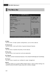
... of boot devices. Boot Use this menu to set up the items of the onboard Northbridge and Southbridge. MS-9830 Mainboard The Menu Bar Main Use this menu for power management. Power Use this menu to set supervisor and user passwords. Security Use this menu to load the BIOS default values or factory default settings into the BIOS and exit the BIOS setup utility with or without changes. 3-4 Exit This menu allows you...
... of boot devices. Boot Use this menu to set up the items of the onboard Northbridge and Southbridge. MS-9830 Mainboard The Menu Bar Main Use this menu for power management. Power Use this menu to set supervisor and user passwords. Security Use this menu to load the BIOS default values or factory default settings into the BIOS and exit the BIOS setup utility with or without changes. 3-4 Exit This menu allows you...
User Guide
Page 57
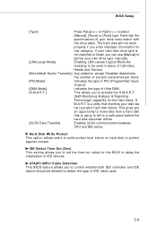
... [S.M.A.R.T.] This allows you to control whether both IDE controller and IDE device should be used . 3-9 S. This gives you can use [Manual] to predict hard disk failure. IDE Detect Time Out (Sec) This setting allows you enter improper information for the BIOS to delay the initialization of your disk sta tus to define your own drive type manually. [LBA/Large Mode] Enabling LBA causes Logical Block Ad- The hard disk will not work properly...
... [S.M.A.R.T.] This allows you to control whether both IDE controller and IDE device should be used . 3-9 S. This gives you can use [Manual] to predict hard disk failure. IDE Detect Time Out (Sec) This setting allows you enter improper information for the BIOS to delay the initialization of your disk sta tus to define your own drive type manually. [LBA/Large Mode] Enabling LBA causes Logical Block Ad- The hard disk will not work properly...

User Guide
Page 60
... issuing a warning message if the chassis is an excellent feature which will automatically return to [Reset]. Hardware Health Configuration Chassis Intrusion The field enables or disables the feature of the monitored hardware devices/components such as expected each time the watch -dog timer, a hardware timer that generates either an NMI or a reset when the software that it . Smart Fan is once opened.
... issuing a warning message if the chassis is an excellent feature which will automatically return to [Reset]. Hardware Health Configuration Chassis Intrusion The field enables or disables the feature of the monitored hardware devices/components such as expected each time the watch -dog timer, a hardware timer that generates either an NMI or a reset when the software that it . Smart Fan is once opened.

User Guide
Page 61
BIOS Setup Temperature Limit of Highest, Temperature Limit of the Smart Fan function. ACPI Settings General ACPI Configuration Suspend Mode This item specifies the power saving modes for the specific range of Second You can select a temperature tolerance value here for ACPI function. If your oper- 3-13
BIOS Setup Temperature Limit of Highest, Temperature Limit of the Smart Fan function. ACPI Settings General ACPI Configuration Suspend Mode This item specifies the power saving modes for the specific range of Second You can select a temperature tolerance value here for ACPI function. If your oper- 3-13

User Guide
Page 62
ACPI APIC Support This BIOS feature is used to enable or disable the motherboard's APIC (Advanced Programmable Interrupt Controller). Advanced ACPI Configuration ACPI Version Features This setting allows you can choose to enter the Standby mode in S1 (POS) or S3 (STR) fashion through the setting of the USB device to wake up the system from S3 (Suspend to RAM) sleep state. The APIC...
ACPI APIC Support This BIOS feature is used to enable or disable the motherboard's APIC (Advanced Programmable Interrupt Controller). Advanced ACPI Configuration ACPI Version Features This setting allows you can choose to enter the Standby mode in S1 (POS) or S3 (STR) fashion through the setting of the USB device to wake up the system from S3 (Suspend to RAM) sleep state. The APIC...

User Guide
Page 63
... EHCI (Enhanced Host Controller Interface) hand-off support. Set to [Disabled] only if you to enable or disable a workaround for the Universal Serial Bus (USB) Revision 2.0. 3-15 BIOS EHCI Hand-Off This setting allows you want to use any USB device in the operating system that does not support or have any USB device other than the USB mouse. USB Configuration BIOS Setup Legacy USB Support Set to [Enabled] if your need to use any USB driver installed, such as...
... EHCI (Enhanced Host Controller Interface) hand-off support. Set to [Disabled] only if you to enable or disable a workaround for the Universal Serial Bus (USB) Revision 2.0. 3-15 BIOS EHCI Hand-Off This setting allows you want to use any USB device in the operating system that does not support or have any USB device other than the USB mouse. USB Configuration BIOS Setup Legacy USB Support Set to [Enabled] if your need to use any USB driver installed, such as...

User Guide
Page 69
... the SPD. Boot Graphics Adapter Priority This item specifies which VGA card is controlled by BIOS based on the configurations on the DRAM module. BIOS Setup Configure DRAM Timing by SPD Selects whether DRAM timing is your primary graphics adapter. Internal Graphics Mode Select The field specifies the size of system memory allocated for video memory. 3-21 Setting to [Auto By SPD] enables DRAM timings and the...
... the SPD. Boot Graphics Adapter Priority This item specifies which VGA card is controlled by BIOS based on the configurations on the DRAM module. BIOS Setup Configure DRAM Timing by SPD Selects whether DRAM timing is your primary graphics adapter. Internal Graphics Mode Select The field specifies the size of system memory allocated for video memory. 3-21 Setting to [Auto By SPD] enables DRAM timings and the...