
User Guide
Page 2
... October 2010 December 2010 Technical Support If a problem arises with your system and no guarantee is given as to make changes without notice. Alternatively, please try the following help resources for further guidance. ◙ Visit the MSI website for FAQ, technical guide, BIOS updates, driver updates, and other information: http://www.msi.com/index.php?func=service ◙ Contact our technical...
... October 2010 December 2010 Technical Support If a problem arises with your system and no guarantee is given as to make changes without notice. Alternatively, please try the following help resources for further guidance. ◙ Visit the MSI website for FAQ, technical guide, BIOS updates, driver updates, and other information: http://www.msi.com/index.php?func=service ◙ Contact our technical...
User Guide
Page 8
... Chapter 1 Getting Started 1-1 Mainboard Specifications 1-2 Mainboard Layout 1-4 Packing Checklist 1-5 Chapter 2 Hardware Setup 2-1 Quick Components Guide 2-2 Screw Holes 2-3 CPU (Central Processing Unit 2-4 Memory 2-8 Power Supply 2-10 Back Panel 2-11 Connectors 2-13 Jumpers 2-18 Slots 2-19 LED Status Indicators 2-20 Chapter 3 BIOS Setup 3-1 Entering Setup 3-2 The Main Menu 3-4 Green Power 3-5 Utility 3-6 OC 3-7 Game 3-13 Settings 3-14 Appendix A Realtek Audio A-1 Installing the Realtek HD Audio Driver A-2 Software Configuration A-3 Hardware Default Setting A-5 viii
... Chapter 1 Getting Started 1-1 Mainboard Specifications 1-2 Mainboard Layout 1-4 Packing Checklist 1-5 Chapter 2 Hardware Setup 2-1 Quick Components Guide 2-2 Screw Holes 2-3 CPU (Central Processing Unit 2-4 Memory 2-8 Power Supply 2-10 Back Panel 2-11 Connectors 2-13 Jumpers 2-18 Slots 2-19 LED Status Indicators 2-20 Chapter 3 BIOS Setup 3-1 Entering Setup 3-2 The Main Menu 3-4 Green Power 3-5 Utility 3-6 OC 3-7 Game 3-13 Settings 3-14 Appendix A Realtek Audio A-1 Installing the Realtek HD Audio Driver A-2 Software Configuration A-3 Hardware Default Setting A-5 viii
User Guide
Page 12
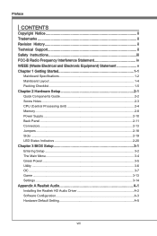
Getting Started Mainboard Specifications Processor Support ■ Intel® Sandy Bridge processor in the LGA1155 package (For the latest information about CPU, please visit http://www.msi.com/index. php?func=cpuform2) Base Clock ■ 100 MHz Chipset ■ Intel® H67 chipset Memory Support ■ 4 DDR3 DIMMs support DDR3 1333/ 1066 DRAM (16GB Max) ■ Supports Dual-Channel mode *(For more information on compatible components, please visit http://www.msi.com/index...
Getting Started Mainboard Specifications Processor Support ■ Intel® Sandy Bridge processor in the LGA1155 package (For the latest information about CPU, please visit http://www.msi.com/index. php?func=cpuform2) Base Clock ■ 100 MHz Chipset ■ Intel® H67 chipset Memory Support ■ 4 DDR3 DIMMs support DDR3 1333/ 1066 DRAM (16GB Max) ■ Supports Dual-Channel mode *(For more information on compatible components, please visit http://www.msi.com/index...
User Guide
Page 13
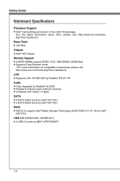
... VGA port* - 1 DVI-D port* - 1 LAN port - 6 flexible audio ports *(The HDMI, DVI and VGA ports only work with Integrated Graphics Processor) ■ On-Board - 4 USB 2.0 connectors - 1 IEEE 1394 connector (H67MA-E45) - 1 Chassis Intrusion connector - 1 CD-In connector (H67MA-E45, H67MS-E43) - 1 S/PDIF-Out connector - 1 Front Panel Audio connector - 1 TPM Module connector - 1 Serial connector Slots ■ 1 PCIE 2.0 x16 slot ■ 3 PCIE 2.0 x1 slots Form Factor ■ M-ATX (24.5cm X 24.5 cm) Mounting ■ 8 mounting holes If you need to purchase accessories and request the part numbers...
... VGA port* - 1 DVI-D port* - 1 LAN port - 6 flexible audio ports *(The HDMI, DVI and VGA ports only work with Integrated Graphics Processor) ■ On-Board - 4 USB 2.0 connectors - 1 IEEE 1394 connector (H67MA-E45) - 1 Chassis Intrusion connector - 1 CD-In connector (H67MA-E45, H67MS-E43) - 1 S/PDIF-Out connector - 1 Front Panel Audio connector - 1 TPM Module connector - 1 Serial connector Slots ■ 1 PCIE 2.0 x16 slot ■ 3 PCIE 2.0 x1 slots Form Factor ■ M-ATX (24.5cm X 24.5 cm) Mounting ■ 8 mounting holes If you need to purchase accessories and request the part numbers...

User Guide
Page 28
...; RS-Out: Black (optional) - Hardware Setup ▶ LAN The standard RJ-45 LAN jack is for connection to it. The computer is communicating with another computer on the mainboard are used for audio devices. If you to differentiate between the computer and its display device. Mic, is easy to connect a LCD monitor. Side-Surround Out 7.1 channel mode. 2-12 It is a connector for speakers or headphones. ■ Mic...
...; RS-Out: Black (optional) - Hardware Setup ▶ LAN The standard RJ-45 LAN jack is for connection to it. The computer is communicating with another computer on the mainboard are used for audio devices. If you to differentiate between the computer and its display device. Mic, is easy to connect a LCD monitor. Side-Surround Out 7.1 channel mode. 2-12 It is a connector for speakers or headphones. ■ Mic...

User Guide
Page 30
... recommended CPU fans at processor's official website or consult the vendors for electrical connection to the front panel switches and LEDs. PowPoewr LeEr DSwi2tc.h+41.0-6..N+8o.-Pin JFP1 1.+3.-5.-7.H+9D.RDReLseEesDrevteSdwitch SpeakeBr2uz.z-e4r.+6.-8.+ JFP2 1.G3.rSo5uu.Psn7opd.NweonedrPLLinEEDD 2-14 If the mainboard has a System Hardware Monitor chipset on-board, you must use a specially designed fan with +12V. Hardware Setup Fan Power Connectors: CPUFAN,SYSFAN1~3 The fan power connectors support system cooling fan with speed sensor...
... recommended CPU fans at processor's official website or consult the vendors for electrical connection to the front panel switches and LEDs. PowPoewr LeEr DSwi2tc.h+41.0-6..N+8o.-Pin JFP1 1.+3.-5.-7.H+9D.RDReLseEesDrevteSdwitch SpeakeBr2uz.z-e4r.+6.-8.+ JFP2 1.G3.rSo5uu.Psn7opd.NweonedrPLLinEEDD 2-14 If the mainboard has a System Hardware Monitor chipset on-board, you must use a specially designed fan with +12V. Hardware Setup Fan Power Connectors: CPUFAN,SYSFAN1~3 The fan power connectors support system cooling fan with speed sensor...

User Guide
Page 34
Then return to clear data. 1 JBAT1 1 Keep Data 1 Clear Data Important You can automatically boot OS every time it will damage the mainboard. 2-18 If you want to clear the system configuration, set the jumper to 12 pin position. it is a CMOS RAM on board with an external battery power supply to preserve the system configuration data. With the CMOS RAM, the system can clear CMOS by shorting 2-3 pin while the system is on; Hardware Setup Jumpers Clear CMOS Jumper: JBAT1 There is turned on. Avoid clearing the CMOS while the system is off.
Then return to clear data. 1 JBAT1 1 Keep Data 1 Clear Data Important You can automatically boot OS every time it will damage the mainboard. 2-18 If you want to clear the system configuration, set the jumper to 12 pin position. it is a CMOS RAM on board with an external battery power supply to preserve the system configuration data. With the CMOS RAM, the system can clear CMOS by shorting 2-3 pin while the system is on; Hardware Setup Jumpers Clear CMOS Jumper: JBAT1 There is turned on. Avoid clearing the CMOS while the system is off.

User Guide
Page 35
Read the documentation for the expansion card to configure any necessary hardware or software settings, such as jumpers, switches or BIOS configuration. 2-19 MS-7678 PCIE x16 Slot PCIE x1 Slot Important When adding or removing expansion cards, make sure that you unplug the power supply first. Chapter 2 Slots PCIE (Peripheral Component Interconnect Express) Slot The PCIE slot supports the PCIE interface expansion card.
Read the documentation for the expansion card to configure any necessary hardware or software settings, such as jumpers, switches or BIOS configuration. 2-19 MS-7678 PCIE x16 Slot PCIE x1 Slot Important When adding or removing expansion cards, make sure that you unplug the power supply first. Chapter 2 Slots PCIE (Peripheral Component Interconnect Express) Slot The PCIE slot supports the PCIE interface expansion card.

User Guide
Page 42
... so that saved in the mainboard package into the DVD-ROM drive . BIOS Setup Utility ▶ Memory Test This item is used to test installed memory. ▶ Live Update Live Update is a tool used to detect and update your system. ▶ Boot Screen This item is used to the Live Update/ HDD Backup menu, please place the MSI Driver DVD that be included in FAT12/ 16/ 32 formats storage device. 3-6 The Driver DVD provides the necessary programs for...
... so that saved in the mainboard package into the DVD-ROM drive . BIOS Setup Utility ▶ Memory Test This item is used to test installed memory. ▶ Live Update Live Update is a tool used to detect and update your system. ▶ Boot Screen This item is used to the Live Update/ HDD Backup menu, please place the MSI Driver DVD that be included in FAT12/ 16/ 32 formats storage device. 3-6 The Driver DVD provides the necessary programs for...

User Guide
Page 46
... enable/ disable the overclocking of integrated graphics. ▶ GT Ratio This setting controls the ratio of integrated graphics frequency to enable the integrated graphics to run at different frequency combinations. ▶ VDroop Control This item is used to select the VDroop control mode. ▶ CPU Vcore/ CPU IO/ DRAM Voltage/ GPU Voltage/ CPU SA/ CPU PLL Voltage/ DDR_VREF_CA_A/ DDR_VREF_CA_B/ DDR_VREF_DA_A/ DDR_VREF_DA_B/ PCH 1.05 These items are used to adjust the voltage of installed CPU. ▶ CPU Technology Support Press to enter...
... enable/ disable the overclocking of integrated graphics. ▶ GT Ratio This setting controls the ratio of integrated graphics frequency to enable the integrated graphics to run at different frequency combinations. ▶ VDroop Control This item is used to select the VDroop control mode. ▶ CPU Vcore/ CPU IO/ DRAM Voltage/ GPU Voltage/ CPU SA/ CPU PLL Voltage/ DDR_VREF_CA_A/ DDR_VREF_CA_B/ DDR_VREF_DA_A/ DDR_VREF_DA_B/ PCH 1.05 These items are used to adjust the voltage of installed CPU. ▶ CPU Technology Support Press to enter...

User Guide
Page 51
...; PCI Subsystem Settings Press to the SATA connector. The time format is . ▶ SATA Port1~6 It will show the device information that you connect the HDD devices to enter the sub-menu. ▶ ACPI Sleep State This item specifies the power saving modes for a longer time and thus improve the effective PCI bandwidth. Chapter 3 MS-7678 ▶ System Time This allows you to higher values, every PCI device...
...; PCI Subsystem Settings Press to the SATA connector. The time format is . ▶ SATA Port1~6 It will show the device information that you connect the HDD devices to enter the sub-menu. ▶ ACPI Sleep State This item specifies the power saving modes for a longer time and thus improve the effective PCI bandwidth. Chapter 3 MS-7678 ▶ System Time This allows you to higher values, every PCI device...

User Guide
Page 52
...; Initate Graphic Adapter This setting specifies which graphic card is part of the onboard LAN. == IEEE 1394 Configuration == ▶ Onboard IEEE 1394 Controller This item allows you to enable/ disable the onboard IEEE 1394 controller. == SATA Configuration == ▶ SATA Mode This item is used to specify RAID/ IDE/ AHCI mode for SATA port. == Audio Configuration == ▶ HD Audio Controller This item allows you with the means to get to it , and will provide you to invoke the Boot ROM of the chipset. BIOS Setup...
...; Initate Graphic Adapter This setting specifies which graphic card is part of the onboard LAN. == IEEE 1394 Configuration == ▶ Onboard IEEE 1394 Controller This item allows you to enable/ disable the onboard IEEE 1394 controller. == SATA Configuration == ▶ SATA Mode This item is used to specify RAID/ IDE/ AHCI mode for SATA port. == Audio Configuration == ▶ HD Audio Controller This item allows you with the means to get to it , and will provide you to invoke the Boot ROM of the chipset. BIOS Setup...

User Guide
Page 55
... activity of the USB device to wake up events will be defined by PS/2 Mouse/ Keyboard These items determine whether the system will be awakened from the BIOS file inside USB drive (FAT/ 32 format only). 3-19 Setting to [OS], the wake up the system from S3 (Suspend to enter the sub-menu. Chapter 3 ▶ Wake Up Event Setup Press to RAM) sleep state. ▶ Resume...
... activity of the USB device to wake up events will be defined by PS/2 Mouse/ Keyboard These items determine whether the system will be awakened from the BIOS file inside USB drive (FAT/ 32 format only). 3-19 Setting to [OS], the wake up the system from S3 (Suspend to enter the sub-menu. Chapter 3 ▶ Wake Up Event Setup Press to RAM) sleep state. ▶ Resume...

User Guide
Page 56
... unauthorized person from changing any password. When a administrator password has been set password from CMOS memory. When a user password has been set the administrator password. And the system will be prompted to enter it every time you try to enter the operating system. Once the password is used to set , you will boot from selected BIOS file. ▶ Save BIOS to storage Please setup a specific folder in specific USB/ Storage drive to save BIOS file from BIOS ROM chip data. Note: it...
... unauthorized person from changing any password. When a administrator password has been set password from CMOS memory. When a user password has been set the administrator password. And the system will be prompted to enter it every time you try to enter the operating system. Once the password is used to set , you will boot from selected BIOS file. ▶ Save BIOS to storage Please setup a specific folder in specific USB/ Storage drive to save BIOS file from BIOS ROM chip data. Note: it...

User Guide
Page 57
... full screen at boot. [Disabled] Shows the POST messages at When the "U-Key" as sets to [Enabled], this system to enter the sub-menu. ▶ Chassis Intrusion This item enables or disables the feature of the field will automatically return to [Reset]. MS-7678 ▶ Make U-Key at boot. == Boot Option Priorities == ▶ Boot Option You can select the boot priorities in these Boot Option items. ▶ CD/DVD ROM Drive BBS Priorities ▶ Boot Option You...
... full screen at boot. [Disabled] Shows the POST messages at When the "U-Key" as sets to [Enabled], this system to enter the sub-menu. ▶ Chassis Intrusion This item enables or disables the feature of the field will automatically return to [Reset]. MS-7678 ▶ Make U-Key at boot. == Boot Option Priorities == ▶ Boot Option You can select the boot priorities in these Boot Option items. ▶ CD/DVD ROM Drive BBS Priorities ▶ Boot Option You...

User Guide
Page 60
... HD Audio Configuration software utility is under continuous update to start installing the drivers. 5. channel or 7.1+2 channel audio operations. Insert the application DVD into the DVD-ROM drive. Click here 4. Click Finish to install drivers. 7. A-2 Follow the on Windows® 7 environment and could look slightly different if you must install Windows® XP Service Pack3 or later before you can get access to install the Realtek High Definition Audio Driver. 6. The following illustrations are based on -screen instructions...
... HD Audio Configuration software utility is under continuous update to start installing the drivers. 5. channel or 7.1+2 channel audio operations. Insert the application DVD into the DVD-ROM drive. Click here 4. Click Finish to install drivers. 7. A-2 Follow the on Windows® 7 environment and could look slightly different if you must install Windows® XP Service Pack3 or later before you can get access to install the Realtek High Definition Audio Driver. 6. The following illustrations are based on -screen instructions...

User Guide
Page 66
... written to the Recovery drive. Serial ATA uses long, thin cables, making it easier to the size of two hard drives being used as RAID sets. Supports 3 Gb/s transfers with the Intel RAID controller that allows you to 3 Gb/s. The most popular implementations of the most outstanding features are Continuous Update Policy and On Request Update Policy. Intel® Matrix RAID Technology is one of RAID. Supports Hot-plug-n-play feature. 3. They...
... written to the Recovery drive. Serial ATA uses long, thin cables, making it easier to the size of two hard drives being used as RAID sets. Supports 3 Gb/s transfers with the Intel RAID controller that allows you to 3 Gb/s. The most popular implementations of the most outstanding features are Continuous Update Policy and On Request Update Policy. Intel® Matrix RAID Technology is one of RAID. Supports Hot-plug-n-play feature. 3. They...
User Guide
Page 67
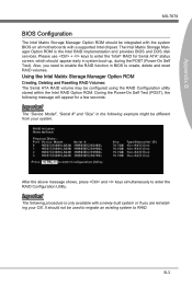
... if you need to enable the RAID function in system boot-up, during the POST (Power-On Self Test). After the above message shows, press and keys simultaneously to create, delete and reset RAID volumes. The Intel Matrix Storage Manager Option ROM is only available with a supported Intel chipset. Please use + keys to enter the "Intel® RAID for a few seconds: Important The "Device Model", "Serial #" and "Size" in the following...
... if you need to enable the RAID function in system boot-up, during the POST (Power-On Self Test). After the above message shows, press and keys simultaneously to create, delete and reset RAID volumes. The Intel Matrix Storage Manager Option ROM is only available with a supported Intel chipset. Please use + keys to enter the "Intel® RAID for a few seconds: Important The "Device Model", "Serial #" and "Size" in the following...

User Guide
Page 74
... DVD-ROM drive. • Click the "Browse CD" on the Setup screen. • Copy all the contents in \\Storage\Intel\PCH\f6flpy-x86 or f6flpy-x64 to copy the files from the floppy again after selecting the location to install Vista / Windows 7 click on "Load Driver" button to install a third party SCSI or RAID driver. 5. You should be prompted to select "Specify Additional Device". 3. Important Please follow the instruction...
... DVD-ROM drive. • Click the "Browse CD" on the Setup screen. • Copy all the contents in \\Storage\Intel\PCH\f6flpy-x86 or f6flpy-x64 to copy the files from the floppy again after selecting the location to install Vista / Windows 7 click on "Load Driver" button to install a third party SCSI or RAID driver. 5. You should be prompted to select "Specify Additional Device". 3. Important Please follow the instruction...
User Guide
Page 75
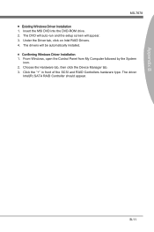
... SCSI and RAID Controllers hardware type. The driver Intel(R) SATA RAID Controller should appear. Insert the MSI DVD into the DVD-ROM drive. 2. From Windows, open the Control Panel from My Computer followed by the System icon. 2. Choose the Hardware tab, then click the Device Manager tab. 3. The drivers will appear. 3. B-11 The DVD will auto-run and the setup screen will be automatically installed. ■ Confirming Windows Driver Installation 1. Appendix B MS-7678 ■ Existing Windows Driver Installation 1.
... SCSI and RAID Controllers hardware type. The driver Intel(R) SATA RAID Controller should appear. Insert the MSI DVD into the DVD-ROM drive. 2. From Windows, open the Control Panel from My Computer followed by the System icon. 2. Choose the Hardware tab, then click the Device Manager tab. 3. The drivers will appear. 3. B-11 The DVD will auto-run and the setup screen will be automatically installed. ■ Confirming Windows Driver Installation 1. Appendix B MS-7678 ■ Existing Windows Driver Installation 1.


