User Manual
Page 1
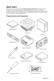
... the URL to the URL by scanning the QR code. Quick Start Thank you for purchasing the MSI® B450M BAZOOKA MAX WIFI motherboard. This Quick Start section provides demonstration diagrams about how to install your phone or tablet. Preparing Tools and Components AMD® AM4 CPU CPU Fan DDR4 Memory Power Supply Unit Chassis Graphics Card Thermal Paste SATA Hard Disk Drive SATA DVD Drive Phillips Screwdriver A Package of the installations also provide video demonstrations. Some of Screws Quick...
... the URL to the URL by scanning the QR code. Quick Start Thank you for purchasing the MSI® B450M BAZOOKA MAX WIFI motherboard. This Quick Start section provides demonstration diagrams about how to install your phone or tablet. Preparing Tools and Components AMD® AM4 CPU CPU Fan DDR4 Memory Power Supply Unit Chassis Graphics Card Thermal Paste SATA Hard Disk Drive SATA DVD Drive Phillips Screwdriver A Package of the installations also provide video demonstrations. Some of Screws Quick...
User Manual
Page 13
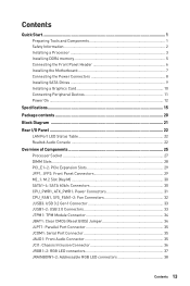
... Panel Header 6 Installing the Motherboard 7 Connecting the Power Connectors 8 Installing SATA Drives 9 Installing a Graphics Card 10 Connecting Peripheral Devices 11 Power On...12 Specifications...15 Package contents 20 Block Diagram ...21 Rear I/O Panel...22 LAN Port LED Status Table 22 Realtek Audio Console 22 Overview of Components 25 Processor Socket 27 DIMM Slots...28 PCI_E1~2: PCIe Expansion Slots 29 JFP1, JFP2: Front Panel Connectors 29 M2_1: M.2 Slot (Key M 30 SATA1~4: SATA 6Gb/s Connectors 30 CPU_PWR1, ATX_PWR1: Power Connectors 31 CPU_FAN1, SYS_FAN1~2: Fan Connectors...
... Panel Header 6 Installing the Motherboard 7 Connecting the Power Connectors 8 Installing SATA Drives 9 Installing a Graphics Card 10 Connecting Peripheral Devices 11 Power On...12 Specifications...15 Package contents 20 Block Diagram ...21 Rear I/O Panel...22 LAN Port LED Status Table 22 Realtek Audio Console 22 Overview of Components 25 Processor Socket 27 DIMM Slots...28 PCI_E1~2: PCIe Expansion Slots 29 JFP1, JFP2: Front Panel Connectors 29 M2_1: M.2 Slot (Key M 30 SATA1~4: SATA 6Gb/s Connectors 30 CPU_PWR1, ATX_PWR1: Power Connectors 31 CPU_FAN1, SYS_FAN1~2: Fan Connectors...
User Manual
Page 14
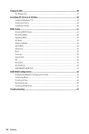
Onboard LEDs...39 EZ Debug LED...39 Installing OS, Drivers & Utilities 40 Installing Windows® 10 40 Installing Drivers 40 Installing Utilities 40 BIOS Setup...41 Entering BIOS Setup 41 Resetting BIOS...42 Updating BIOS...42 EZ Mode...43 Advanced Mode ...45 SETTINGS...46 Advanced...46 Boot...52 Security...53 Save & Exit...54 OC...55 M-FLASH...59 OC PROFILE...60 HARDWARE MONITOR 61 AMD RAID Configuration 62 Enabling RAIDXpert2 Configuration Utility 62 Initializing Disks...63 Creating Arrays...64 Deleting Arrays...65 Installing RAID Driver 66 Troubleshooting 67 14 Contents
Onboard LEDs...39 EZ Debug LED...39 Installing OS, Drivers & Utilities 40 Installing Windows® 10 40 Installing Drivers 40 Installing Utilities 40 BIOS Setup...41 Entering BIOS Setup 41 Resetting BIOS...42 Updating BIOS...42 EZ Mode...43 Advanced Mode ...45 SETTINGS...46 Advanced...46 Boot...52 Security...53 Save & Exit...54 OC...55 M-FLASH...59 OC PROFILE...60 HARDWARE MONITOR 61 AMD RAID Configuration 62 Enabling RAIDXpert2 Configuration Utility 62 Initializing Disks...63 Creating Arrays...64 Deleting Arrays...65 Installing RAID Driver 66 Troubleshooting 67 14 Contents
User Manual
Page 15
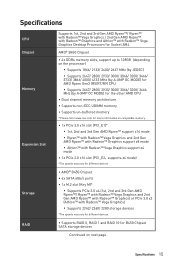
...;4x SATA 6Gb/s ports ∙∙1x M.2 slot (Key M)* ▪▪Supports PCIe 3.0 x4 (1st, 2nd and 3rd Gen AMD Ryzen™/ Ryzen™ with Radeon™ Vega Graphics and 2nd Gen AMD Ryzen™ with Radeon™ Graphics) or PCIe 3.0 x2 (Athlon™ with Radeon™ Vega Graphics) ▪▪Supports 2242/ 2260/ 2280 storage devices *The speeds may vary for different devices ∙∙Supports RAID 0, RAID 1 and RAID...
...;4x SATA 6Gb/s ports ∙∙1x M.2 slot (Key M)* ▪▪Supports PCIe 3.0 x4 (1st, 2nd and 3rd Gen AMD Ryzen™/ Ryzen™ with Radeon™ Vega Graphics and 2nd Gen AMD Ryzen™ with Radeon™ Graphics) or PCIe 3.0 x2 (Athlon™ with Radeon™ Vega Graphics) ▪▪Supports 2242/ 2260/ 2280 storage devices *The speeds may vary for different devices ∙∙Supports RAID 0, RAID 1 and RAID...
User Manual
Page 17
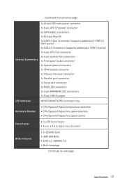
...previous page Internal Connectors 1x 24-pin ATX main power connector 1x 8-pin ATX 12V power connector 4x SATA 6Gb/s connectors 1x M.2 slot (Key M) 1x USB 3.2 Gen1 connector (supports additional 2 USB 3.2 Gen1 ports) 2x USB 2.0 connectors (supports additional 4 USB 2.0 ports) 1x 4-pin CPU Fan connector 2x 4-pin system Fan connectors 1x Front panel audio connector 2x System panel connectors 1x TPM module connector 1x Chassis Intrusion connector 1x Parallel port connector 1x Serial port connector 2x RGB LED connectors 2x 3-pin RAINBOW LED connectors 1x Clear CMOS jumper I/O Controller NUVOTON...
...previous page Internal Connectors 1x 24-pin ATX main power connector 1x 8-pin ATX 12V power connector 4x SATA 6Gb/s connectors 1x M.2 slot (Key M) 1x USB 3.2 Gen1 connector (supports additional 2 USB 3.2 Gen1 ports) 2x USB 2.0 connectors (supports additional 4 USB 2.0 ports) 1x 4-pin CPU Fan connector 2x 4-pin system Fan connectors 1x Front panel audio connector 2x System panel connectors 1x TPM module connector 1x Chassis Intrusion connector 1x Parallel port connector 1x Serial port connector 2x RGB LED connectors 2x 3-pin RAINBOW LED connectors 1x Clear CMOS jumper I/O Controller NUVOTON...

User Manual
Page 29
...10 9 Reserved HDD LED Reset Switch 1 HDD LED + 2 3 HDD LED - 4 5 Reset Switch 6 7 Reset Switch 8 9 Reserved 10 Power LED + Power LED Power Switch Power Switch No Pin JFP2 1 + - + Buzzer 1 Speaker - 2 Speaker 3 Buzzer - 4 Buzzer + Speaker + Overview of the slot. ∙∙When adding or removing expansion cards, always turn off the power supply and unplug the power supply power cable from the power outlet. Read the expansion card's documentation to the switches and LEDs on the front panel. JFP1, JFP2: Front Panel Connectors These connectors connect to check...
...10 9 Reserved HDD LED Reset Switch 1 HDD LED + 2 3 HDD LED - 4 5 Reset Switch 6 7 Reset Switch 8 9 Reserved 10 Power LED + Power LED Power Switch Power Switch No Pin JFP2 1 + - + Buzzer 1 Speaker - 2 Speaker 3 Buzzer - 4 Buzzer + Speaker + Overview of the slot. ∙∙When adding or removing expansion cards, always turn off the power supply and unplug the power supply power cable from the power outlet. Read the expansion card's documentation to the switches and LEDs on the front panel. JFP1, JFP2: Front Panel Connectors These connectors connect to check...
User Manual
Page 38
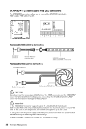
... connector and the JRAINBOW connector provide different voltages, and connecting the 5V LED strip to the JRGB connector will result in damage to the LED strip. ⚠⚠Important ∙∙The JRAINBOW connector supports up to 200 LEDs. ∙∙Always turn off the power supply and unplug the power cord from the power outlet before installing or removing the RGB LED strip. ∙∙Please use MSI's software to control...
... connector and the JRAINBOW connector provide different voltages, and connecting the 5V LED strip to the JRGB connector will result in damage to the LED strip. ⚠⚠Important ∙∙The JRAINBOW connector supports up to 200 LEDs. ∙∙Always turn off the power supply and unplug the power cord from the power outlet before installing or removing the RGB LED strip. ∙∙Please use MSI's software to control...
User Manual
Page 40
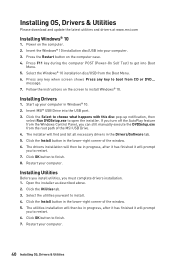
... computer. 3. Power on the computer case. 4. Select the Windows® 10 installation disc/USB from CD or DVD... Click the Utilities tab. 3. Click OK button to install Windows® 10. Insert the Windows® 10 installation disc/USB into the USB port. 3. Installing OS, Drivers & Utilities Please download and update the latest utilities and drivers at www.msi.com Installing Windows® 10 1. Installing Drivers 1. If you turn off the AutoPlay feature from the Windows Control Panel, you can still manually execute...
... computer. 3. Power on the computer case. 4. Select the Windows® 10 installation disc/USB from CD or DVD... Click the Utilities tab. 3. Click OK button to install Windows® 10. Insert the Windows® 10 installation disc/USB into the USB port. 3. Installing OS, Drivers & Utilities Please download and update the latest utilities and drivers at www.msi.com Installing Windows® 10 1. Installing Drivers 1. If you turn off the AutoPlay feature from the Windows Control Panel, you can still manually execute...
User Manual
Page 42
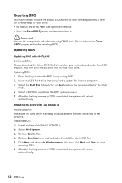
... download and install the latest BIOS file. 5. Click Next and choose In Windows mode. Insert the USB flash drive that matches your motherboard model from MSI website. Click on Scan button. 4. Updating BIOS Updating BIOS with Live Update 6 Before updating: Make sure the LAN driver is already installed and the internet connection is off before clearing CMOS data. Install and launch MSI LIVE UPDATE 6. 2. After the flashing process is 100% completed, the system will restart automatically. 42 BIOS Setup Press Del key...
... download and install the latest BIOS file. 5. Click Next and choose In Windows mode. Insert the USB flash drive that matches your motherboard model from MSI website. Click on Scan button. 4. Updating BIOS Updating BIOS with Live Update 6 Before updating: Make sure the LAN driver is already installed and the internet connection is off before clearing CMOS data. Install and launch MSI LIVE UPDATE 6. 2. After the flashing process is 100% completed, the system will restart automatically. 42 BIOS Setup Press Del key...
User Manual
Page 43
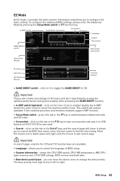
...; Setup Mode switch - This switch will show. EZ Mode At EZ mode, it provides the basic system information and allows you to search by pressing the Setup Mode switch or F7 function key. To configure the advanced BIOS settings, please enter the Advanced Mode by BIOS item name, enter the item name to find the item listing. shows the CPU/ DDR speed, CPU/ MB temperature, MB/ CPU type, memory size, CPU/ DDR voltage, BIOS version and build date. ∙∙ Boot device...
...; Setup Mode switch - This switch will show. EZ Mode At EZ mode, it provides the basic system information and allows you to search by pressing the Setup Mode switch or F7 function key. To configure the advanced BIOS settings, please enter the Advanced Mode by BIOS item name, enter the item name to find the item listing. shows the CPU/ DDR speed, CPU/ MB temperature, MB/ CPU type, memory size, CPU/ DDR voltage, BIOS version and build date. ∙∙ Boot device...
User Manual
Page 44
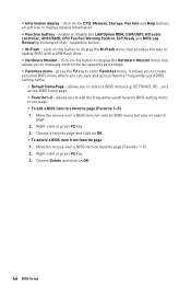
... update BIOS with a USB flash drive. ∙∙ Hardware Monitor - click on this button to display the M-Flash menu that allows you can save and access favorite/ frequently-used / favorite BIOS setting items in one page. ▪▪To add a BIOS item to a favorite page (Favorite 1~5) 1. enable or disable the LAN Option ROM, CSM/UEFI, HD audio controller, AHCI/RAID, CPU Fan Fail Warning Control, ErP Ready and BIOS Log Review by percentage. ∙∙ Favorites menu - allows you to manually control the fan speed...
... update BIOS with a USB flash drive. ∙∙ Hardware Monitor - click on this button to display the M-Flash menu that allows you can save and access favorite/ frequently-used / favorite BIOS setting items in one page. ▪▪To add a BIOS item to a favorite page (Favorite 1~5) 1. enable or disable the LAN Option ROM, CSM/UEFI, HD audio controller, AHCI/RAID, CPU Fan Fail Warning Control, ErP Ready and BIOS Log Review by percentage. ∙∙ Favorites menu - allows you to manually control the fan speed...
User Manual
Page 47
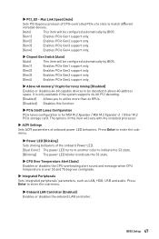
... alert sound and message when CPU temperature is for MSI M.2 Xpander / MSI M.2 Xpander-Z / Other M.2 PCIe storage card. Press Enter to enter the submenu. ▶▶Power LED [Blinking] Sets shining behaviors of onboard power LED behaviors. The options in above 4G address space. It is only available if the system supports 64-bit PCI decoding. [Enabled] Allows you to enter the sub-menu. ▶▶Onboard LAN Controller [Enabled] Enables or disables the onboard LAN controller. ▶▶PCI_EX - BIOS Setup 47 Press Enter to utilize...
... alert sound and message when CPU temperature is for MSI M.2 Xpander / MSI M.2 Xpander-Z / Other M.2 PCIe storage card. Press Enter to enter the submenu. ▶▶Power LED [Blinking] Sets shining behaviors of onboard power LED behaviors. The options in above 4G address space. It is only available if the system supports 64-bit PCI decoding. [Enabled] Allows you to enter the sub-menu. ▶▶Onboard LAN Controller [Enabled] Enables or disables the onboard LAN controller. ▶▶PCI_EX - BIOS Setup 47 Press Enter to utilize...
User Manual
Page 48
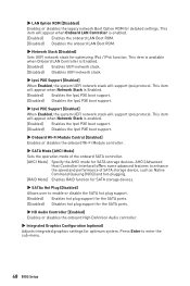
.... [AHCI Mode] Specify the AHCI mode for detailed settings. Press Enter to enable or disable the SATA hot plug support. [Enabled] Enables hot plug support for the SATA ports. [Disabled] Disables hot plug support for the SATA ports. ▶▶HD Audio Controller [Enabled] Enables or disables the onboard High Definition Audio controller. ▶▶Integrated Graphics Configuration (optional) Adjusts integrated graphics settings for optimizing IPv4 / IPv6 function. ▶▶LAN Option ROM [Disabled] Enables or disables the legacy network Boot Option ROM for SATA storage devices...
.... [AHCI Mode] Specify the AHCI mode for detailed settings. Press Enter to enable or disable the SATA hot plug support. [Enabled] Enables hot plug support for the SATA ports. [Disabled] Disables hot plug support for the SATA ports. ▶▶HD Audio Controller [Enabled] Enables or disables the onboard High Definition Audio controller. ▶▶Integrated Graphics Configuration (optional) Adjusts integrated graphics settings for optimizing IPv4 / IPv6 function. ▶▶LAN Option ROM [Disabled] Enables or disables the legacy network Boot Option ROM for SATA storage devices...
User Manual
Page 49
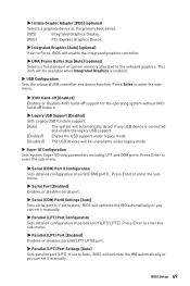
... (LPT) Port Settings [Auto] Sets parallel port (LPT). This item will be available when Integrated Graphics is connected and enable the legacy USB support. [Enabled] Enable the USB support under legacy mode. [Disabled] The USB devices will be unavailable under legacy mode. ▶▶Super IO Configuration Sets system Super I/O chip parameters including LPT and COM ports. Press Enter to the onboard graphics. If set to Auto, BIOS will enable the integrated graphics controller. ▶▶UMA Frame Buffer Size [Auto] (optional) Selects a fixed amount of system memory allocated...
... (LPT) Port Settings [Auto] Sets parallel port (LPT). This item will be available when Integrated Graphics is connected and enable the legacy USB support. [Enabled] Enable the USB support under legacy mode. [Disabled] The USB devices will be unavailable under legacy mode. ▶▶Super IO Configuration Sets system Super I/O chip parameters including LPT and COM ports. Press Enter to the onboard graphics. If set to Auto, BIOS will enable the integrated graphics controller. ▶▶UMA Frame Buffer Size [Auto] (optional) Selects a fixed amount of system memory allocated...
User Manual
Page 50
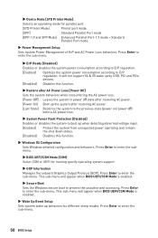
... enabled. ▶▶Secure Boot Sets the Windows secure boot to enter the submenu. ▶▶BIOS UEFI/CSM Mode [CSM] Select CSM or UEFI for parallel port. [STD Printer Mode] Printer port mode [SPP] Standard Parallel Port mode [EPP-1.9 and SPP Mode] Enhanced Parallel Port-1.9 mode + Standard Parallel Port mode. ▶▶Power Management Setup Sets system Power Management of ErP and AC Power Loss behaviors. This sub-menu will not support S4 & S5 wake up by USB, PCI and PCIe devices. [Disabled] Disables...
... enabled. ▶▶Secure Boot Sets the Windows secure boot to enter the submenu. ▶▶BIOS UEFI/CSM Mode [CSM] Select CSM or UEFI for parallel port. [STD Printer Mode] Printer port mode [SPP] Standard Parallel Port mode [EPP-1.9 and SPP Mode] Enhanced Parallel Port-1.9 mode + Standard Parallel Port mode. ▶▶Power Management Setup Sets system Power Management of ErP and AC Power Loss behaviors. This sub-menu will not support S4 & S5 wake up by USB, PCI and PCIe devices. [Disabled] Disables...
User Manual
Page 51
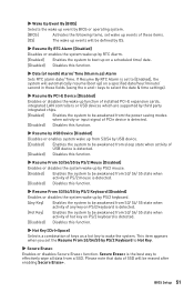
.../2 Keyboard [Disabled] Enables or disables the system wake up by PS/2 keyboard. [Any Key] Enables the system to wake the system. keys to select the date & time settings). ▶▶Resume By PCI-E Device [Disabled] Enables or disables the wake up function of installed PCI-E expansion cards, integrated LAN controllers or USB devices which are supported by third party integrated chips. [Enabled] Enables the system to be awakened from the power saving modes when activity or input signal of PCIe device is...
.../2 Keyboard [Disabled] Enables or disables the system wake up by PS/2 keyboard. [Any Key] Enables the system to wake the system. keys to select the date & time settings). ▶▶Resume By PCI-E Device [Disabled] Enables or disables the wake up function of installed PCI-E expansion cards, integrated LAN controllers or USB devices which are supported by third party integrated chips. [Enabled] Enables the system to be awakened from the power saving modes when activity or input signal of PCIe device is...
User Manual
Page 52
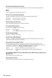
... USB Key Drive BBS Priorities/ USB Key Drive BBS Priorities Sets device priority for system boot. ▶▶Boot Option Priorities These items are used to OS and reboot repeatedly. ▶▶Boot Mode Select [LEGACY+UEFI] Sets the system boot mode from legacy or UEFI architecture depending on the screen. ▶▶POST Beep [Disabled] Enables or disables POST beep. ▶▶AUTO CLR_CMOS [Disabled] Enables or disables the CMOS data to be configured automatically by BIOS when Windows 10 WHQL Support is enabled. [UEFI] [LEGACY+UEFI] Enables UEFI BIOS boot mode support...
... USB Key Drive BBS Priorities/ USB Key Drive BBS Priorities Sets device priority for system boot. ▶▶Boot Option Priorities These items are used to OS and reboot repeatedly. ▶▶Boot Mode Select [LEGACY+UEFI] Sets the system boot mode from legacy or UEFI architecture depending on the screen. ▶▶POST Beep [Disabled] Enables or disables POST beep. ▶▶AUTO CLR_CMOS [Disabled] Enables or disables the CMOS data to be configured automatically by BIOS when Windows 10 WHQL Support is enabled. [UEFI] [LEGACY+UEFI] Enables UEFI BIOS boot mode support...
User Manual
Page 54
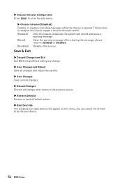
...;▶Restore Defaults Restore or load all default values. ▶▶Boot Override The installed boot-able devices will record and issue a warning message. [Reset] Clear the warning message. After clearing the message, please return to Enabled or Disabled. [Disabled] Disables this menu, you can select one of them to be the boot device. 54 BIOS Setup This function is ready for the chassis equips a chassis intrusion switch. [Enabled] Once the chassis is opened...
...;▶Restore Defaults Restore or load all default values. ▶▶Boot Override The installed boot-able devices will record and issue a warning message. [Reset] Clear the warning message. After clearing the message, please return to Enabled or Disabled. [Disabled] Disables this menu, you can select one of them to be the boot device. 54 BIOS Setup This function is ready for the chassis equips a chassis intrusion switch. [Enabled] Once the chassis is opened...
User Manual
Page 66
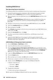
... credentials. 66 AMD RAID Configuration Under the Drivers/Software tab, check the AMD RAID Drivers check-box. 5. AMD RAIDXpert2 Management Suite Installation 1. exe from the Windows Control Panel, you to restart, click OK button to open the installer. admin ▫▫Password - Click the Select to RAID Mode in BIOS 2. You have successfully installed the RAID driver, and Windows setup should continue. 9. When prompted, click OK. 6. When prompt you can still manually execute the DVDSetup...
... credentials. 66 AMD RAID Configuration Under the Drivers/Software tab, check the AMD RAID Drivers check-box. 5. AMD RAIDXpert2 Management Suite Installation 1. exe from the Windows Control Panel, you to restart, click OK button to open the installer. admin ▫▫Password - Click the Select to RAID Mode in BIOS 2. You have successfully installed the RAID driver, and Windows setup should continue. 9. When prompted, click OK. 6. When prompt you can still manually execute the DVDSetup...
User Manual
Page 67
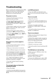
...;∙Connect the USB device to other USB port on the motherboard rear IO panel. ∙∙Remove secondary speakers/ headphones, HDMI cables, USB audio devices. ∙∙Test with another known working graphics card. Troubleshooting Before sending the motherboard for motherboard with another known working speaker or headphone. There is properly connected and make sure the button is turned on the monitor. ∙∙If 3 long beeps are heard, remove all customized settings in the BIOS. Lost BIOS password ∙∙Clear the CMOS...
...;∙Connect the USB device to other USB port on the motherboard rear IO panel. ∙∙Remove secondary speakers/ headphones, HDMI cables, USB audio devices. ∙∙Test with another known working graphics card. Troubleshooting Before sending the motherboard for motherboard with another known working speaker or headphone. There is properly connected and make sure the button is turned on the monitor. ∙∙If 3 long beeps are heard, remove all customized settings in the BIOS. Lost BIOS password ∙∙Clear the CMOS...


