User Manual
Page 12
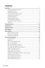
...a Processor 2 Installing DDR4 memory 4 Connecting the Front Panel Header 5 Installing the Motherboard 6 Installing SATA Drives 7 Installing a Graphics Card 8 Connecting Peripheral Devices 9 Connecting the Power Connectors 10 Power On...11 Safety Information 15 Specifications...16 Package contents 20 Block Diagram ...21 Rear I/O Panel ...22 LAN Port LED Status Table 22 Audio Ports Configuration 22 Realtek HD Audio Manager 23 Overview of Components 25 Processor Socket 27 DIMM Slots...28 PCI_E1~6: PCIe Expansion Slots 29 M2_1: M.2 Slot (Key M 30 SATA1~6: SATA 6Gb/s Connectors 31...
...a Processor 2 Installing DDR4 memory 4 Connecting the Front Panel Header 5 Installing the Motherboard 6 Installing SATA Drives 7 Installing a Graphics Card 8 Connecting Peripheral Devices 9 Connecting the Power Connectors 10 Power On...11 Safety Information 15 Specifications...16 Package contents 20 Block Diagram ...21 Rear I/O Panel ...22 LAN Port LED Status Table 22 Audio Ports Configuration 22 Realtek HD Audio Manager 23 Overview of Components 25 Processor Socket 27 DIMM Slots...28 PCI_E1~6: PCIe Expansion Slots 29 M2_1: M.2 Slot (Key M 30 SATA1~6: SATA 6Gb/s Connectors 31...
User Manual
Page 13
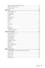
... Resetting BIOS...39 Updating BIOS...39 EZ Mode ...41 Advanced Mode ...43 SETTINGS...44 Advanced...44 Boot...49 Security ...50 Save & Exit...51 OC...53 M-FLASH ...57 OC PROFILE ...58 HARDWARE MONITOR 59 Software Description 60 Installing Windows® 10 60 Installing Drivers 60 Installing Utilities 60 APP MANAGER ...61 LIVE UPDATE 6...62 COMMAND CENTER 64 X-BOOST ...68 MYSTIC LIGHT...70 MYSTIC LIGHT PARTY 74 SMART TOOL...78 RAMDISK...80 RAID Configuration 81 Using AMD RAID Controller BIOS Configuration Utility...
... Resetting BIOS...39 Updating BIOS...39 EZ Mode ...41 Advanced Mode ...43 SETTINGS...44 Advanced...44 Boot...49 Security ...50 Save & Exit...51 OC...53 M-FLASH ...57 OC PROFILE ...58 HARDWARE MONITOR 59 Software Description 60 Installing Windows® 10 60 Installing Drivers 60 Installing Utilities 60 APP MANAGER ...61 LIVE UPDATE 6...62 COMMAND CENTER 64 X-BOOST ...68 MYSTIC LIGHT...70 MYSTIC LIGHT PARTY 74 SMART TOOL...78 RAMDISK...80 RAID Configuration 81 Using AMD RAID Controller BIOS Configuration Utility...
User Manual
Page 17
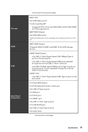
...CPU y 2x SATA 6Gb/s ports* y 1x M.2 slot (Key M)* ƒ Supports PCIe 3.0 x4 and SATA 6Gb/s 2242/ 2260 /2280/ 22110 storage devices AMD® B450 Chipset y 4x SATA 6Gb/s ports * SATA5 and SATA6 ports will be unavailable when installing a M.2 device in M.2 slot. AMD® B450 Chipset y Supports RAID 0, RAID1 and RAID 10 for SATA storage devices y AMD® B450 Chipset ƒ 2x USB 3.1 Gen2 (SuperSpeed USB 10Gbps) Type-A ports on the back panel ƒ 2x USB 3.1 Gen1 (SuperSpeed USB) ports available through the internal USB 3.1 Gen1 connector ƒ 6x USB 2.0 (High-speed USB) ports (2 Type...
...CPU y 2x SATA 6Gb/s ports* y 1x M.2 slot (Key M)* ƒ Supports PCIe 3.0 x4 and SATA 6Gb/s 2242/ 2260 /2280/ 22110 storage devices AMD® B450 Chipset y 4x SATA 6Gb/s ports * SATA5 and SATA6 ports will be unavailable when installing a M.2 device in M.2 slot. AMD® B450 Chipset y Supports RAID 0, RAID1 and RAID 10 for SATA storage devices y AMD® B450 Chipset ƒ 2x USB 3.1 Gen2 (SuperSpeed USB 10Gbps) Type-A ports on the back panel ƒ 2x USB 3.1 Gen1 (SuperSpeed USB) ports available through the internal USB 3.1 Gen1 connector ƒ 6x USB 2.0 (High-speed USB) ports (2 Type...
User Manual
Page 39
... system and enter the flash mode. 4. Updating BIOS Updating BIOS with Live Update 6 Before updating: Make sure the LAN driver is already installed and the internet connection is 100% completed, the system will restart automatically. Press Del key to perform the BIOS update process. 5. Insert the USB flash drive that matches your motherboard model from MSI website. Updating the BIOS with M-FLASH Before updating: Please download the latest BIOS file that contains the update file into the USB flash drive. y Short the Clear CMOS jumper on Scan button. 4. And...
... system and enter the flash mode. 4. Updating BIOS Updating BIOS with Live Update 6 Before updating: Make sure the LAN driver is already installed and the internet connection is 100% completed, the system will restart automatically. Press Del key to perform the BIOS update process. 5. Insert the USB flash drive that matches your motherboard model from MSI website. Updating the BIOS with M-FLASH Before updating: Please download the latest BIOS file that contains the update file into the USB flash drive. y Short the Clear CMOS jumper on Scan button. 4. And...
User Manual
Page 41
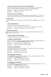
... change the boot priority. y Setup Mode switch - y Screenshot - shows the CPU/ DDR speed, CPU/ MB temperature, MB/ CPU type, memory size, CPU/ DDR voltage, BIOS version and build date. you can move the device icons to right. BIOS Setup 41 EZ Mode At EZ mode, it provides the basic system information and allows you to find the item listing. A-XMP switch Setup Mode switch Screenshot Search Language System information OC GENIE 4 switch Boot device priority bar Information display M-Flash Favorites Hardware Monitor Function buttons...
... change the boot priority. y Setup Mode switch - y Screenshot - shows the CPU/ DDR speed, CPU/ MB temperature, MB/ CPU type, memory size, CPU/ DDR voltage, BIOS version and build date. you can move the device icons to right. BIOS Setup 41 EZ Mode At EZ mode, it provides the basic system information and allows you to find the item listing. A-XMP switch Setup Mode switch Screenshot Search Language System information OC GENIE 4 switch Boot device priority bar Information display M-Flash Favorites Hardware Monitor Function buttons...
User Manual
Page 42
... this button to display the Hardware Monitor menu that provides the way to add the frequently-used BIOS setting items. ƒ Default HomePage - It allows you to create personal BIOS menu where you to update BIOS with a USB flash drive. Right-click or press F2 key. 3. click on this button to display the M-Flash menu that allows you to select a BIOS menu (e.g. enable or disable the LAN Option ROM, HD audio controller, AHCI/RAID, CPU Fan Fail Warning Control, Windows 10 WHQL support and BIOS Log Review by...
... this button to display the Hardware Monitor menu that provides the way to add the frequently-used BIOS setting items. ƒ Default HomePage - It allows you to create personal BIOS menu where you to update BIOS with a USB flash drive. Right-click or press F2 key. 3. click on this button to display the M-Flash menu that allows you to select a BIOS menu (e.g. enable or disable the LAN Option ROM, HD audio controller, AHCI/RAID, CPU Fan Fail Warning Control, Windows 10 WHQL support and BIOS Log Review by...
User Manual
Page 43
... overclocking profiles. ƒ HARDWARE MONITOR - allows you to set the speeds of fans and monitor voltages of system. ƒ BOARD EXPLORER - A-XMP switch Setup Mode switch Screenshot Search Language System information OC GENIE 4 switch Boot device priority bar BIOS menu selection BIOS menu selection Menu display y OC GENIE 4 switch/ Setup Mode switch/ Screenshot/ Language/ System information/ Boot device priority bar - allows you to the descriptions of installed devices on this motherboard. Advanced Mode Press Setup Mode switch or F7 function key can switch between EZ Mode...
... overclocking profiles. ƒ HARDWARE MONITOR - allows you to set the speeds of fans and monitor voltages of system. ƒ BOARD EXPLORER - A-XMP switch Setup Mode switch Screenshot Search Language System information OC GENIE 4 switch Boot device priority bar BIOS menu selection BIOS menu selection Menu display y OC GENIE 4 switch/ Setup Mode switch/ Screenshot/ Language/ System information/ Boot device priority bar - allows you to the descriptions of installed devices on this motherboard. Advanced Mode Press Setup Mode switch or F7 function key can switch between EZ Mode...
User Manual
Page 45
.... f ACPI Settings Sets ACPI parameters of the onboard Power LED. [Dual Color] The power LED turns to another color to indicate the S3 state. [Blinking] The power LED blinks to enter the submenu. fOnboard LAN Controller [Enabled] Enables or disables the onboard LAN controller. fLAN Option ROM [Disabled] Enables or disables the legacy network Boot Option ROM for detailed settings. f Integrated Peripherals Sets integrated peripherals' parameters, such as LAN, HDD, USB and audio. fIpv4 PXE Support [Enabled] When Enabled, the system UEFI network stack will vary with the installed processor...
.... f ACPI Settings Sets ACPI parameters of the onboard Power LED. [Dual Color] The power LED turns to another color to indicate the S3 state. [Blinking] The power LED blinks to enter the submenu. fOnboard LAN Controller [Enabled] Enables or disables the onboard LAN controller. fLAN Option ROM [Disabled] Enables or disables the legacy network Boot Option ROM for detailed settings. f Integrated Peripherals Sets integrated peripherals' parameters, such as LAN, HDD, USB and audio. fIpv4 PXE Support [Enabled] When Enabled, the system UEFI network stack will vary with the installed processor...
User Manual
Page 46
...Sets the onboard USB controller and device function. fInitiate Graphic Adapter [PEG] (optional) Selects a graphics device as Native Command Queuing (NCQ) and hot-plugging. [RAID Mode] Enables RAID function for SATA storage devices. fUMA Frame Buffer Size [Auto] (optional) Selects a fixed amount of system memory allocated to enter the submenu. fXHCI Hand-off [Enabled] Enables or disables XHCI hand-off support for optimum system. fSATA Mode [AHCI Mode] Sets the operation mode of SATA storage device, such as the primary boot device. [IGD] Integrated Graphics Display. [PEG] PCI-Express...
...Sets the onboard USB controller and device function. fInitiate Graphic Adapter [PEG] (optional) Selects a graphics device as Native Command Queuing (NCQ) and hot-plugging. [RAID Mode] Enables RAID function for SATA storage devices. fUMA Frame Buffer Size [Auto] (optional) Selects a fixed amount of system memory allocated to enter the submenu. fXHCI Hand-off [Enabled] Enables or disables XHCI hand-off support for optimum system. fSATA Mode [AHCI Mode] Sets the operation mode of SATA storage device, such as the primary boot device. [IGD] Integrated Graphics Display. [PEG] PCI-Express...
User Manual
Page 47
... (COM) Port0 Settings [Auto] Sets serial port 0. fErP Ready [Disabled] Enables or disables the system power consumption according to ErP regulation. [Enabled] Optimize the system power consumption according to enter the submenu. fParallel (LPT) Port Settings [Auto] Sets parallel port (LPT). fRestore after restoring AC power. [Power On] Boot up by USB, PCI and PCIe devices. [Disabled] Disables this function. fParallel (LPT) Port Configuration Sets detailed configuration of serial(COM) port 0. If set to Auto, BIOS will not support S4 & S5 wake up the...
... (COM) Port0 Settings [Auto] Sets serial port 0. fErP Ready [Disabled] Enables or disables the system power consumption according to ErP regulation. [Enabled] Optimize the system power consumption according to enter the submenu. fParallel (LPT) Port Settings [Auto] Sets parallel port (LPT). fRestore after restoring AC power. [Power On] Boot up by USB, PCI and PCIe devices. [Disabled] Disables this function. fParallel (LPT) Port Configuration Sets detailed configuration of serial(COM) port 0. If set to Auto, BIOS will not support S4 & S5 wake up the...
User Manual
Page 48
... WHQL Support [Disabled] Enables the supports for Windows 10 or disables for different sleep modes. Press Enter to select the date & time settings). 48 BIOS Setup fResume By RTC Alarm [Disabled] Disables or enables the system wake up by RTC Alarm. [Enabled] Enables the system to boot up ) on a scheduled time/ date. [Disabled] Disables this function. Press Enter to prevent the unauthorized accessing. fSecure Boot Sets the Windows secure boot to enter the sub-menu. fSystem Power Fault Protection [Disabled] Enables or disables...
... WHQL Support [Disabled] Enables the supports for Windows 10 or disables for different sleep modes. Press Enter to select the date & time settings). 48 BIOS Setup fResume By RTC Alarm [Disabled] Disables or enables the system wake up by RTC Alarm. [Enabled] Enables the system to boot up ) on a scheduled time/ date. [Disabled] Disables this function. Press Enter to prevent the unauthorized accessing. fSecure Boot Sets the Windows secure boot to enter the sub-menu. fSystem Power Fault Protection [Disabled] Enables or disables...
User Manual
Page 49
... PCI-E Device [Disabled] Enables or disables the wake up function of installed PCI-E expansion cards, integrated LAN controllers or USB devices which are supported by third party integrated chips. [Enabled] Enables the system to be erased after enabling Secure Erase+. f Secure Erase+ Enables or disables Secure Erase+ function. Please note that data of SSD will be awakened from the power saving modes when activity or input signal of PCIe device is detected. [Disabled] Disables this function. Boot Sets...
... PCI-E Device [Disabled] Enables or disables the wake up function of installed PCI-E expansion cards, integrated LAN controllers or USB devices which are supported by third party integrated chips. [Enabled] Enables the system to be erased after enabling Secure Erase+. f Secure Erase+ Enables or disables Secure Erase+ function. Please note that data of SSD will be awakened from the power saving modes when activity or input signal of PCIe device is detected. [Disabled] Disables this function. Boot Sets...
User Manual
Page 51
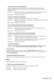
... chassis equips a chassis intrusion switch. [Enabled] Once the chassis is enabled. [AMD CPU fTPM] Select it for AMD Firmware TPM. [AMD CPU fTPM Disabled] Select it for accessing the system. Save & Exit f Discard Changes and Exit Exit BIOS setup without authorization. fSecurity Device Support [Disabled] Enables or disables the TPM function to Enabled or Disabled. [Disabled] Disables this funcion. Type the password then press Enter. You will detect the TPM 2.0 or TPM 1.2 model automatically. A message will replace any change. fDevice Select [Auto] Sets the version...
... chassis equips a chassis intrusion switch. [Enabled] Once the chassis is enabled. [AMD CPU fTPM] Select it for AMD Firmware TPM. [AMD CPU fTPM Disabled] Select it for accessing the system. Save & Exit f Discard Changes and Exit Exit BIOS setup without authorization. fSecurity Device Support [Disabled] Enables or disables the TPM function to Enabled or Disabled. [Disabled] Disables this funcion. Type the password then press Enter. You will detect the TPM 2.0 or TPM 1.2 model automatically. A message will replace any change. fDevice Select [Auto] Sets the version...
User Manual
Page 53
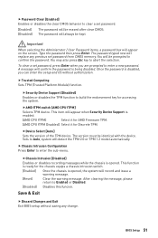
... installed processor, memory modules and motherboard support this function. f A-XMP [Disabled] Please enable A-XMP or select a profile of OC settings. [Normal] Provides the regular OC settings in BIOS setup. f CPU Ratio [Auto] Sets the CPU ratio that is only recommended for OC expert to determine CPU clock speed. Note: We use OC GENIE 4 function for overclocking the memory. This item appears when the installed CPU supports this function. y If you to be changed if the processor supports...
... installed processor, memory modules and motherboard support this function. f A-XMP [Disabled] Please enable A-XMP or select a profile of OC settings. [Normal] Provides the regular OC settings in BIOS setup. f CPU Ratio [Auto] Sets the CPU ratio that is only recommended for OC expert to determine CPU clock speed. Note: We use OC GENIE 4 function for overclocking the memory. This item appears when the installed CPU supports this function. y If you to be changed if the processor supports...
User Manual
Page 55
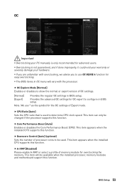
... instruction is repeated. This item appears when the installed CPU supports this function and keeps the current BIOS settings. BIOS Setup 55 f DRAM Voltages control [Auto] These options allows you to set the voltages related to CPU. f Memory Changed Detect [Enabled]* Enables or disables the system to issue a warning message during boot when the memory has been replaced. [Enabled] [Disabled] The system will configure this information menu at any time by pressing [F5]. The sub-menu displays the information of installed memory...
... instruction is repeated. This item appears when the installed CPU supports this function and keeps the current BIOS settings. BIOS Setup 55 f DRAM Voltages control [Auto] These options allows you to set the voltages related to CPU. f Memory Changed Detect [Enabled]* Enables or disables the system to issue a warning message during boot when the memory has been replaced. [Enabled] [Disabled] The system will configure this information menu at any time by pressing [F5]. The sub-menu displays the information of installed memory...
User Manual
Page 56
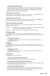
.... [Disabled] Part-specific EDC throttling protection enabled. It manages PSP sub-items including all cores are plagued by BIOS. [Custom Setting] Allows you to select the power-saving control mode for I /O Memory Management Unit) for the CPU when all C2P/P2C mailbox, Secure S3, fTPM support. If set the currents manually. 56 BIOS Setup fIOMMU Mode (optional) Enables/disables the IOMMU (I /O Virtualization. fCPU VDD_SoC Current Optimization [Auto] (optional) Sets the currents of CPU Base clock. fSpread Spectrum (optional...
.... [Disabled] Part-specific EDC throttling protection enabled. It manages PSP sub-items including all cores are plagued by BIOS. [Custom Setting] Allows you to select the power-saving control mode for I /O Memory Management Unit) for the CPU when all C2P/P2C mailbox, Secure S3, fTPM support. If set the currents manually. 56 BIOS Setup fIOMMU Mode (optional) Enables/disables the IOMMU (I /O Virtualization. fCPU VDD_SoC Current Optimization [Auto] (optional) Sets the currents of CPU Base clock. fSpread Spectrum (optional...
User Manual
Page 57
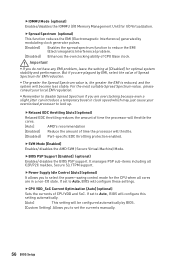
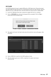
... update BIOS with a USB flash drive. Click on M-FLASH tab, a demand message will appear after rebooting. 4. The system will enter the flash mode and a file selection menu will be prompted. Select a BIOS file to update BIOS. 1. Please download the latest BIOS file that contains the update file into your USB flash drive. After the flashing process is 100% completed, the system will reboot automatically. BIOS Setup 57 Insert the USB flash drive that matches your motherboard model from MSI website, save the BIOS file...
... update BIOS with a USB flash drive. Click on M-FLASH tab, a demand message will appear after rebooting. 4. The system will enter the flash mode and a file selection menu will be prompted. Select a BIOS file to update BIOS. 1. Please download the latest BIOS file that contains the update file into your USB flash drive. After the flashing process is 100% completed, the system will reboot automatically. BIOS Setup 57 Insert the USB flash drive that matches your motherboard model from MSI website, save the BIOS file...

User Manual
Page 60
... Installing Windows® 10 1. Installing Drivers 1. Insert MSI® Driver Disc into your optical drive. 3. The software installation will prompt you to restart. 7. Press the Restart button on the computer. 2. Click OK button to finish. 8. Restart your computer. 60 Software Description Insert MSI® Driver Disc into your optical drive from CD or DVD... message. 7. Insert the Windows® 10 disc into Boot Menu. 5. Press F11 key during the computer POST (Power...
... Installing Windows® 10 1. Installing Drivers 1. Insert MSI® Driver Disc into your optical drive. 3. The software installation will prompt you to restart. 7. Press the Restart button on the computer. 2. Click OK button to finish. 8. Restart your computer. 60 Software Description Insert MSI® Driver Disc into your optical drive from CD or DVD... message. 7. Insert the Windows® 10 disc into Boot Menu. 5. Press F11 key during the computer POST (Power...
User Manual
Page 91
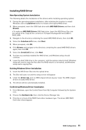
... the disk/ USB drive in \\Chipset\Packages\Drivers\SBDrv\ RAID_AM4 3. The Disc will auto-run and the setup screen will be automatically installed. Navigate to the directory containing the saved AMD RAID drivers again, then click OK. 7. Existing Windows Driver Installation 1. Insert the MSI Driver Disc into the optical drive. Confirming Windows Driver Installation 1. From Windows, open the Control Panel from My Computer followed by your need to copy the files after selecting the location to install...
... the disk/ USB drive in \\Chipset\Packages\Drivers\SBDrv\ RAID_AM4 3. The Disc will auto-run and the setup screen will be automatically installed. Navigate to the directory containing the saved AMD RAID drivers again, then click OK. 7. Existing Windows Driver Installation 1. Insert the MSI Driver Disc into the optical drive. Confirming Windows Driver Installation 1. From Windows, open the Control Panel from My Computer followed by your need to copy the files after selecting the location to install...
User Manual
Page 92
... motherboard for motherboard with Dual BIOS) 92 Troubleshooting y Some power supply units have a power button on the rear side, make sure the LAN port LEDs are heard, remove all ATX power connectors like ATX_PWR1, CPU_PWR1 are heard, remove and reinstall the graphics card and then restart the computer. y Test with another known working speaker or headphone. The power is turned on . y If 1 long 2 short beeps are connected from the power supply to other USB port on the monitor. Lost BIOS password y Clear the CMOS, but no audio...
... motherboard for motherboard with Dual BIOS) 92 Troubleshooting y Some power supply units have a power button on the rear side, make sure the LAN port LEDs are heard, remove all ATX power connectors like ATX_PWR1, CPU_PWR1 are heard, remove and reinstall the graphics card and then restart the computer. y Test with another known working speaker or headphone. The power is turned on . y If 1 long 2 short beeps are connected from the power supply to other USB port on the monitor. Lost BIOS password y Clear the CMOS, but no audio...


