User Manual
Page 13
... 36 JRGB1: RGB LED connector 37 EZ Debug LEDs ...37 BIOS Setup ...38 Entering BIOS Setup 38 Resetting BIOS...39 Updating BIOS...39 EZ Mode ...41 Advanced Mode ...43 SETTINGS...44 Advanced...44 Boot...49 Security ...50 Save & Exit...51 OC...53 M-FLASH ...57 OC PROFILE ...58 ... 6...62 COMMAND CENTER 64 X-BOOST ...68 MYSTIC LIGHT...70 MYSTIC LIGHT PARTY 74 SMART TOOL...78 RAMDISK...80 RAID Configuration 81 Using AMD RAID Controller BIOS Configuration Utility 81 Initialize Disks ...83 Create Arrays...84 Delete Arrays ...85 Swap Arrays...86 Manage Spares ...87 Contents 13
... 36 JRGB1: RGB LED connector 37 EZ Debug LEDs ...37 BIOS Setup ...38 Entering BIOS Setup 38 Resetting BIOS...39 Updating BIOS...39 EZ Mode ...41 Advanced Mode ...43 SETTINGS...44 Advanced...44 Boot...49 Security ...50 Save & Exit...51 OC...53 M-FLASH ...57 OC PROFILE ...58 ... 6...62 COMMAND CENTER 64 X-BOOST ...68 MYSTIC LIGHT...70 MYSTIC LIGHT PARTY 74 SMART TOOL...78 RAMDISK...80 RAID Configuration 81 Using AMD RAID Controller BIOS Configuration Utility 81 Initialize Disks ...83 Create Arrays...84 Delete Arrays ...85 Swap Arrays...86 Manage Spares ...87 Contents 13
User Manual
Page 17
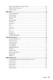
...SATA 6Gb/s ports * SATA5 and SATA6 ports will be unavailable when installing a M.2 device in M.2 slot. AMD® B450 Chipset y Supports RAID 0, RAID1 and RAID 10 for SATA storage devices y AMD® B450 Chipset ƒ 2x USB 3.1 Gen2 (SuperSpeed USB 10Gbps) Type-A ports on the back panel ƒ 2x USB ...4 ports available through the internal USB 2.0 connectors) y AMD® CPU ƒ 2x USB 3.1 Gen1 (SuperSpeed USB) Type-A ports on the back panel y 1x Flash BIOS Button y 1x PS/2 keyboard/ mouse combo port y 2x USB 2.0 Type-A ports y 1x VGA port y 1x DVI-D port y 1x HDMI™ port y 2x USB...
...SATA 6Gb/s ports * SATA5 and SATA6 ports will be unavailable when installing a M.2 device in M.2 slot. AMD® B450 Chipset y Supports RAID 0, RAID1 and RAID 10 for SATA storage devices y AMD® B450 Chipset ƒ 2x USB 3.1 Gen2 (SuperSpeed USB 10Gbps) Type-A ports on the back panel ƒ 2x USB ...4 ports available through the internal USB 2.0 connectors) y AMD® CPU ƒ 2x USB 3.1 Gen1 (SuperSpeed USB) Type-A ports on the back panel y 1x Flash BIOS Button y 1x PS/2 keyboard/ mouse combo port y 2x USB 2.0 Type-A ports y 1x VGA port y 1x DVI-D port y 1x HDMI™ port y 2x USB...

User Manual
Page 18
... y CPU/System temperature detection y CPU/System fan speed detection y CPU/System fan speed control Form Factor y ATX Form Factor y 12 in . (30.5 cm x 24.4 cm) BIOS Features y 1x 128 Mb flash y UEFI AMI BIOS y ACPI 6.1, SM BIOS 2.8 y Multi-language Continued on next page 18 Specifications x 9.6 in .
... y CPU/System temperature detection y CPU/System fan speed detection y CPU/System fan speed control Form Factor y ATX Form Factor y 12 in . (30.5 cm x 24.4 cm) BIOS Features y 1x 128 Mb flash y UEFI AMI BIOS y ACPI 6.1, SM BIOS 2.8 y Multi-language Continued on next page 18 Specifications x 9.6 in .

User Manual
Page 20
...; PCIe Steel Slot y Performance ƒ Multi GPU-CrossFire Technology ƒ DDR4 Boost ƒ AMD Turbo USB 3.1 Gen 2 ƒ CORE Boost y VR ƒ VR Ready y BIOS ƒ Click BIOS 5 Package contents Please check the contents of the above items are damaged or missing, please contact your motherboard package. It should contain: y Motherboard y Driver...
...; PCIe Steel Slot y Performance ƒ Multi GPU-CrossFire Technology ƒ DDR4 Boost ƒ AMD Turbo USB 3.1 Gen 2 ƒ CORE Boost y VR ƒ VR Ready y BIOS ƒ Click BIOS 5 Package contents Please check the contents of the above items are damaged or missing, please contact your motherboard package. It should contain: y Motherboard y Driver...

User Manual
Page 22
Please refer to page 40 for Updating BIOS with Flash BIOS Button. LAN Port LED Status Table Link/ Activity LED Status Off Yellow Blinking Description No link Linked Data activity Speed LED Status Off Green Orange .../ Front Speaker Out Rear Speaker Out Center/ Subwoofer Out Side Speaker Out ●● ● Mic In (●: connected, Blank: empty) 22 Rear I /O Panel Flash BIOS Port PS/2 VGA USB 3.1 Gen1 Type-A LAN Audio Ports USB 2.0 Type-A Flash...
Please refer to page 40 for Updating BIOS with Flash BIOS Button. LAN Port LED Status Table Link/ Activity LED Status Off Yellow Blinking Description No link Linked Data activity Speed LED Status Off Green Orange .../ Front Speaker Out Rear Speaker Out Center/ Subwoofer Out Side Speaker Out ●● ● Mic In (●: connected, Blank: empty) 22 Rear I /O Panel Flash BIOS Port PS/2 VGA USB 3.1 Gen1 Type-A LAN Audio Ports USB 2.0 Type-A Flash...

User Manual
Page 27
...to prevent overheating and maintain system stability. y Overheating can tolerate overclocking. y This motherboard is necessary to install a CPU heatsink. MSI® does not guarantee the damages or risks caused by inadequate operation beyond product specifications is the Pin 1 indicator. Overview of Components...power outlet before booting your system. Important y When changing the processor, the system configuration could be cleared and reset BIOS to default values, due to operate beyond product specifications. Any attempt to the AM4 processor's architecture. Processor Socket ...
...to prevent overheating and maintain system stability. y Overheating can tolerate overclocking. y This motherboard is necessary to install a CPU heatsink. MSI® does not guarantee the damages or risks caused by inadequate operation beyond product specifications is the Pin 1 indicator. Overview of Components...power outlet before booting your system. Important y When changing the processor, the system configuration could be cleared and reset BIOS to default values, due to operate beyond product specifications. Any attempt to the AM4 processor's architecture. Processor Socket ...

User Manual
Page 28
...the Memory DIMM voltage below 1.35V is recommended to protect the processor. y The stability and compatibility of installed. Please refer www.msi.com for full DIMMs installation or overclocking. y Based on installed CPU and devices when overclocking. y Some memory modules may operate ... It is suggested to use a more efficient memory cooling system for more information on its Serial Presence Detect (SPD). y Due to BIOS and find the DRAM Frequency! y Due to the memory frequency operates dependent on compatible memory. 28 Overview of memory modules may operate ...
...the Memory DIMM voltage below 1.35V is recommended to protect the processor. y The stability and compatibility of installed. Please refer www.msi.com for full DIMMs installation or overclocking. y Based on installed CPU and devices when overclocking. y Some memory modules may operate ... It is suggested to use a more efficient memory cooling system for more information on its Serial Presence Detect (SPD). y Due to BIOS and find the DRAM Frequency! y Due to the memory frequency operates dependent on compatible memory. 28 Overview of memory modules may operate ...

User Manual
Page 34
... and DC mode and adjust fan speed in PWM mode, the fan speed will auto detect the fan mode. When you to a fan connector in BIOS > HARDWARE MONITOR. You can be classified as PWM (Pulse Width Modulation) Mode or DC Mode. JCOM1: Serial Port Connector This connector allows you plug a 3-pin...
... and DC mode and adjust fan speed in PWM mode, the fan speed will auto detect the fan mode. When you to a fan connector in BIOS > HARDWARE MONITOR. You can be classified as PWM (Pulse Width Modulation) Mode or DC Mode. JCOM1: Serial Port Connector This connector allows you plug a 3-pin...
User Manual
Page 35
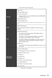
... warning 1. Press F10 to save and exit and then press the Enter key to select Yes. 6. JCI1: Chassis Intrusion Connector This connector allows you to BIOS > SETTINGS > Security > Chassis Intrusion Configuration. 4. Connect the JCI1 connector to select Yes. Go to connect the chassis intrusion switch cable. Press F10 to save and... (default) Trigger the chassis intrusion event Using chassis intrusion detector 1. Go to the TPM security platform manual for TPM (Trusted Platform Module). Please refer to BIOS > SETTINGS > Security > Chassis Intrusion Configuration. 2.
... warning 1. Press F10 to save and exit and then press the Enter key to select Yes. 6. JCI1: Chassis Intrusion Connector This connector allows you to BIOS > SETTINGS > Security > Chassis Intrusion Configuration. 4. Connect the JCI1 connector to select Yes. Go to connect the chassis intrusion switch cable. Press F10 to save and... (default) Trigger the chassis intrusion event Using chassis intrusion detector 1. Go to the TPM security platform manual for TPM (Trusted Platform Module). Please refer to BIOS > SETTINGS > Security > Chassis Intrusion Configuration. 2.

User Manual
Page 36
Keep Data (default) Clear CMOS/ Reset BIOS Resetting BIOS to clear the CMOS memory. Remove the jumper cap from a battery located on the computer. 36 Overview of Components If you to connect the optional ... 17 PRND7 18 Ground 19 ACK# 20 Ground 21 BUSY 22 Ground 23 PE 24 Ground 25 SLCT 26 No Pin JBAT1: Clear CMOS (Reset BIOS) Jumper There is CMOS memory onboard that is external powered from JBAT1. 4. Use a jumper cap to save system configuration data. Plug the power cord and...
Keep Data (default) Clear CMOS/ Reset BIOS Resetting BIOS to clear the CMOS memory. Remove the jumper cap from a battery located on the computer. 36 Overview of Components If you to connect the optional ... 17 PRND7 18 Ground 19 ACK# 20 Ground 21 BUSY 22 Ground 23 PE 24 Ground 25 SLCT 26 No Pin JBAT1: Clear CMOS (Reset BIOS) Jumper There is CMOS memory onboard that is external powered from JBAT1. 4. Use a jumper cap to save system configuration data. Plug the power cord and...

User Manual
Page 38
... Press Delete key, when the Press DEL key to enter Setup Menu, F11 to the HELP information panel for BIOS item description. Important y BIOS items are continuously update for better system performance. Ctrl+F: Enter Search page * When you press F10, a confirmation window appears and ...it to avoid possible system damage or failure booting unless you are familiar with the processor. y The pictures in normal conditions. BIOS Setup The default settings offer the optimal performance for system stability in this chapter are for reference only and may be slightly different from ...
... Press Delete key, when the Press DEL key to enter Setup Menu, F11 to the HELP information panel for BIOS item description. Important y BIOS items are continuously update for better system performance. Ctrl+F: Enter Search page * When you press F10, a confirmation window appears and ...it to avoid possible system damage or failure booting unless you are familiar with the processor. y The pictures in normal conditions. BIOS Setup The default settings offer the optimal performance for system stability in this chapter are for reference only and may be slightly different from ...
User Manual
Page 39
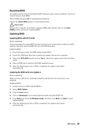
... and enter the flash mode. 4. Updating BIOS: 1. Click Next and choose In Windows mode. After the flashing process is 100% completed, the system will restart automatically. Insert the USB flash drive that matches your motherboard model from MSI website. Select the M-FLASH tab and click... on the motherboard. y Short the Clear CMOS jumper on Yes to enter the BIOS Setup during POST. 2. Updating BIOS Updating BIOS with Live Update 6 Before updating: Make sure the LAN...
... and enter the flash mode. 4. Updating BIOS: 1. Click Next and choose In Windows mode. After the flashing process is 100% completed, the system will restart automatically. Insert the USB flash drive that matches your motherboard model from MSI website. Select the M-FLASH tab and click... on the motherboard. y Short the Clear CMOS jumper on Yes to enter the BIOS Setup during POST. 2. Updating BIOS Updating BIOS with Live Update 6 Before updating: Make sure the LAN...
User Manual
Page 40
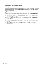
...the FAT32 format USB flash drive supports updating BIOS by Flash BIOS Button. 1. Updating BIOS with Flash BIOS Button Before updating: Please download the latest BIOS file that contains the MSI.ROM file into the Flash BIOS Port on rear I/O panel. 3. And then, save the MSI.ROM file to the button starts flashing. ...Plug the USB flash drive that matches your motherboard model from MSI® website and rename the BIOS file to CPU_PWR1 and ATX_PWR1. (No other components are necessary but power supply.) 2. Press the Flash BIOS Button to flash BIOS, and the LED next to the root of USB flash ...
...the FAT32 format USB flash drive supports updating BIOS by Flash BIOS Button. 1. Updating BIOS with Flash BIOS Button Before updating: Please download the latest BIOS file that contains the MSI.ROM file into the Flash BIOS Port on rear I/O panel. 3. And then, save the MSI.ROM file to the button starts flashing. ...Plug the USB flash drive that matches your motherboard model from MSI® website and rename the BIOS file to CPU_PWR1 and ATX_PWR1. (No other components are necessary but power supply.) 2. Press the Flash BIOS Button to flash BIOS, and the LED next to the root of USB flash ...
User Manual
Page 41
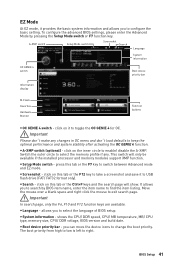
...) - This switch will show. y Screenshot - shows the CPU/ DDR speed, CPU/ MB temperature, MB/ CPU type, memory size, CPU/ DDR voltage, BIOS version and build date. y Boot device priority bar - EZ Mode At EZ mode, it provides the basic system information and allows you to right. y Search... - Important In search page, only the F6, F10 and F12 function keys are available. BIOS Setup 41 Important Please don't make any . A-XMP switch Setup Mode switch Screenshot Search Language System information OC GENIE 4 switch Boot device ...
...) - This switch will show. y Screenshot - shows the CPU/ DDR speed, CPU/ MB temperature, MB/ CPU type, memory size, CPU/ DDR voltage, BIOS version and build date. y Boot device priority bar - EZ Mode At EZ mode, it provides the basic system information and allows you to right. y Search... - Important In search page, only the F6, F10 and F12 function keys are available. BIOS Setup 41 Important Please don't make any . A-XMP switch Setup Mode switch Screenshot Search Language System information OC GENIE 4 switch Boot device ...
User Manual
Page 42
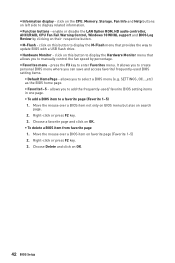
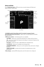
... Help buttons on left side to enter Favorites menu. y M-Flash - allows you to add the frequently-used BIOS setting items. ƒ Default HomePage - Choose a favorite page and click on OK. 42 BIOS Setup Right-click or press F2 key. 3. y Function buttons - click on favorite page (Favorite 1~5) 2. .... enable or disable the LAN Option ROM, HD audio controller, AHCI/RAID, CPU Fan Fail Warning Control, Windows 10 WHQL support and BIOS Log Review by percentage. y Information display - click on this button to display the M-Flash menu that allows you can save and access...
... Help buttons on left side to enter Favorites menu. y M-Flash - allows you to add the frequently-used BIOS setting items. ƒ Default HomePage - Choose a favorite page and click on OK. 42 BIOS Setup Right-click or press F2 key. 3. y Function buttons - click on favorite page (Favorite 1~5) 2. .... enable or disable the LAN Option ROM, HD audio controller, AHCI/RAID, CPU Fan Fail Warning Control, Windows 10 WHQL support and BIOS Log Review by percentage. y Information display - click on this button to display the M-Flash menu that allows you can save and access...
User Manual
Page 43
...ƒ BOARD EXPLORER - Advanced Mode Press Setup Mode switch or F7 function key can switch between EZ Mode and Advanced Mode in BIOS setup. provides BIOS setting items and information to specify the parameters for chipset and boot devices. ƒ OC - allows you to adjust the frequency ...and voltage. y Menu display - allows you to be configured. Increasing the frequency may get better performance. ƒ M-FLASH - y BIOS menu selection - A-XMP switch Setup Mode switch Screenshot Search Language System information OC GENIE 4 switch Boot device priority bar...
...ƒ BOARD EXPLORER - Advanced Mode Press Setup Mode switch or F7 function key can switch between EZ Mode and Advanced Mode in BIOS setup. provides BIOS setting items and information to specify the parameters for chipset and boot devices. ƒ OC - allows you to adjust the frequency ...and voltage. y Menu display - allows you to be configured. Increasing the frequency may get better performance. ƒ M-FLASH - y BIOS menu selection - A-XMP switch Setup Mode switch Screenshot Search Language System information OC GENIE 4 switch Boot device priority bar...

User Manual
Page 44
...of the device and motherboard. through Dec. f SATA PortX Shows the information of the week, from Sun to 31 can be keyed by BIOS. Important If the connected SATA device is . Day of connected SATA device. The date from Jan. The time format is . f DMI...System Time Sets the system time. Use tab key to switch between time elements. f System Information Shows detailed system information, including CPU type, BIOS version, and Memory (read only). Use tab key to switch between date elements. Advanced f PCI Subsystem Settings Sets PCI, PCI express interface ...
...of the device and motherboard. through Dec. f SATA PortX Shows the information of the week, from Sun to 31 can be keyed by BIOS. Important If the connected SATA device is . Day of connected SATA device. The date from Jan. The time format is . f DMI...System Time Sets the system time. Use tab key to switch between time elements. f System Information Shows detailed system information, including CPU type, BIOS version, and Memory (read only). Use tab key to switch between date elements. Advanced f PCI Subsystem Settings Sets PCI, PCI express interface ...
User Manual
Page 45
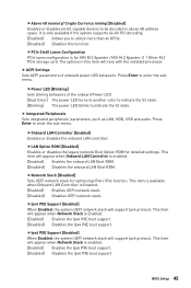
...Enabled] Enables the Ipv6 PXE boot support. [Disabled] Disables the Ipv6 PXE boot support. This item will appear when Onboard LAN Controller is for MSI M.2 Xpander / MSI M.2 Xpander-Z / Other M.2 PCIe storage card. This item will appear when Network Stack is Enabled. [Enabled] Enables UEFI network stack. [Disabled]...Color] The power LED turns to another color to indicate the S3 state. [Blinking] The power LED blinks to indicate the S3 state. BIOS Setup 45 Press Enter to enter the submenu. It is Enabled. [Enabled] Enables the Ipv4 PXE boot support. [Disabled] Disables the ...
...Enabled] Enables the Ipv6 PXE boot support. [Disabled] Disables the Ipv6 PXE boot support. This item will appear when Onboard LAN Controller is for MSI M.2 Xpander / MSI M.2 Xpander-Z / Other M.2 PCIe storage card. This item will appear when Network Stack is Enabled. [Enabled] Enables UEFI network stack. [Disabled]...Color] The power LED turns to another color to indicate the S3 state. [Blinking] The power LED blinks to indicate the S3 state. BIOS Setup 45 Press Enter to enter the submenu. It is Enabled. [Enabled] Enables the Ipv4 PXE boot support. [Disabled] Disables the ...
User Manual
Page 46
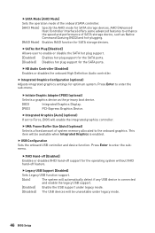
... USB support. [Enabled] Enable the USB support under legacy mode. [Disabled] The USB devices will be unavailable under legacy mode. 46 BIOS Setup Press Enter to enter the sub-menu. fSATA Mode [AHCI Mode] Sets the operation mode of system memory allocated to the onboard graphics.... AHCI (Advanced Host Controller Interface) offers some advanced features to Force, BIOS will automatically detect if any USB device is enabled. fHD Audio Controller [Enabled] Enables or disables the onboard High Definition Audio ...
... USB support. [Enabled] Enable the USB support under legacy mode. [Disabled] The USB devices will be unavailable under legacy mode. 46 BIOS Setup Press Enter to enter the sub-menu. fSATA Mode [AHCI Mode] Sets the operation mode of system memory allocated to the onboard graphics.... AHCI (Advanced Host Controller Interface) offers some advanced features to Force, BIOS will automatically detect if any USB device is enabled. fHD Audio Controller [Enabled] Enables or disables the onboard High Definition Audio ...
User Manual
Page 47
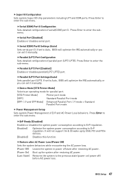
... detailed configuration of ErP and AC Power Loss behaviors. fSerial (COM) Port0 Settings [Auto] Sets serial port 0. Press Enter to Auto, BIOS will optimize the IRQ automatically or you can set to enter the submenu. If set it manually. fParallel (LPT) Port Settings [Auto] Sets parallel... to enter the sub-menu. fSerial Port [Enabled] Enables or disables serial port. Press Enter to ErP regulation. Press Enter to Auto, BIOS will not support S4 & S5 wake up the system after AC Power Loss [Power Off] Sets the system behaviors while encountering the AC ...
... detailed configuration of ErP and AC Power Loss behaviors. fSerial (COM) Port0 Settings [Auto] Sets serial port 0. Press Enter to Auto, BIOS will optimize the IRQ automatically or you can set to enter the submenu. If set it manually. fParallel (LPT) Port Settings [Auto] Sets parallel... to enter the sub-menu. fSerial Port [Enabled] Enables or disables serial port. Press Enter to ErP regulation. Press Enter to Auto, BIOS will not support S4 & S5 wake up the system after AC Power Loss [Power Off] Sets the system behaviors while encountering the AC ...


