User Manual
Page 1
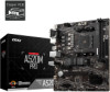
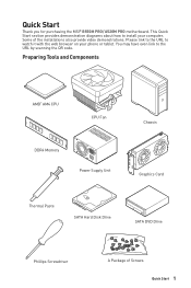
You may have even link to watch it with the web browser on your computer. Quick Start Thank you for purchasing the MSI® B550M PRO/ A520M PRO motherboard. This Quick Start section provides demonstration diagrams about how to install your phone or tablet. Some of Screws Quick Start 1 Please link to the URL ...
You may have even link to watch it with the web browser on your computer. Quick Start Thank you for purchasing the MSI® B550M PRO/ A520M PRO motherboard. This Quick Start section provides demonstration diagrams about how to install your phone or tablet. Some of Screws Quick Start 1 Please link to the URL ...

User Manual
Page 2
...before connecting the PSU to the electrical outlet. ∙∙Place the power cord such a way that people can not get the motherboard checked by the edges to avoid touching sensitive components. ∙∙It is recommended to wear an electrostatic discharge (ESD) wrist strap... when handling the motherboard to damage from the power outlet before installing or removing any installation step, please consult a certified computer technician. ∙∙Always...
...before connecting the PSU to the electrical outlet. ∙∙Place the power cord such a way that people can not get the motherboard checked by the edges to avoid touching sensitive components. ∙∙It is recommended to wear an electrostatic discharge (ESD) wrist strap... when handling the motherboard to damage from the power outlet before installing or removing any installation step, please consult a certified computer technician. ∙∙Always...

User Manual
Page 7
Installing the Motherboard 1 BAT1 2 https://youtu.be/wWI6Qt51Wnc Torque: 3 kgf·cm* 3 BAT1 *3 kgf·cm = 0.3 N·m = 2.6 lbf·in Quick Start 7
Installing the Motherboard 1 BAT1 2 https://youtu.be/wWI6Qt51Wnc Torque: 3 kgf·cm* 3 BAT1 *3 kgf·cm = 0.3 N·m = 2.6 lbf·in Quick Start 7

User Manual
Page 13
Contents Quick Start...1 Preparing Tools and Components 1 Safety Information 2 Installing a Processor 3 Installing DDR4 memory 5 Connecting the Front Panel Header 6 Installing the Motherboard 7 Connecting the Power Connectors 8 Installing SATA Drives 9 Installing a Graphics Card 10 Connecting Peripheral Devices 11 Power On...12 Specifications...15 Package contents 20 Block Diagram ......
Contents Quick Start...1 Preparing Tools and Components 1 Safety Information 2 Installing a Processor 3 Installing DDR4 memory 5 Connecting the Front Panel Header 6 Installing the Motherboard 7 Connecting the Power Connectors 8 Installing SATA Drives 9 Installing a Graphics Card 10 Connecting Peripheral Devices 11 Power On...12 Specifications...15 Package contents 20 Block Diagram ......

User Manual
Page 20
Package contents Please check the contents of the above items are damaged or missing, please contact your motherboard package. It should contain: Motherboard Cable Accessories Application Documentation B550M PRO/ A520M PRO SATA 6G cables (2 cables/pack) 1 M.2 screws (3 pcs./pack) 1 Product registration card 1 IO Shielding 1 Case Badge 1 Driver DVD 1 Quick installation guide 1 MSI components compatibility & reward program card (Only for B550M PRO) 1 ⚠⚠Important If any of your retailer. 20 Package contents
Package contents Please check the contents of the above items are damaged or missing, please contact your motherboard package. It should contain: Motherboard Cable Accessories Application Documentation B550M PRO/ A520M PRO SATA 6G cables (2 cables/pack) 1 M.2 screws (3 pcs./pack) 1 Product registration card 1 IO Shielding 1 Case Badge 1 Driver DVD 1 Quick installation guide 1 MSI components compatibility & reward program card (Only for B550M PRO) 1 ⚠⚠Important If any of your retailer. 20 Package contents
User Manual
Page 26
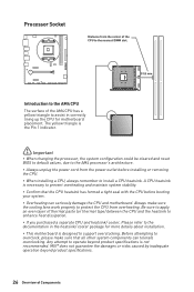
... heatsink/ cooler, Please refer to the documentation in correctly lining up the CPU for more details about installation. ∙∙This motherboard is necessary to the AM4 processor's architecture. ∙∙Always unplug the power cord from the power outlet before booting your system.... ∙∙Overheating can tolerate overclocking. The yellow triangle is not recommended. MSI® does not guarantee the damages or risks caused by inadequate operation beyond product specifications is the Pin 1 indicator. ⚠&#...
... heatsink/ cooler, Please refer to the documentation in correctly lining up the CPU for more details about installation. ∙∙This motherboard is necessary to the AM4 processor's architecture. ∙∙Always unplug the power cord from the power outlet before booting your system.... ∙∙Overheating can tolerate overclocking. The yellow triangle is not recommended. MSI® does not guarantee the damages or risks caused by inadequate operation beyond product specifications is the Pin 1 indicator. ⚠&#...

User Manual
Page 28
... 3.0 x1 (PCH) ⚠⚠Important ∙∙If you install a large and heavy graphics card, you need to use a tool such as MSI Gaming Series Graphics Card Bolster to support its weight to one SATA device. Read the expansion card's documentation to the motherboard for any necessary additional hardware or software changes.
... 3.0 x1 (PCH) ⚠⚠Important ∙∙If you install a large and heavy graphics card, you need to use a tool such as MSI Gaming Series Graphics Card Bolster to support its weight to one SATA device. Read the expansion card's documentation to the motherboard for any necessary additional hardware or software changes.

User Manual
Page 32
... Ground ⚠⚠Important Make sure that all the power cables are securely connected to a proper ATX power supply to ensure stable operation of the motherboard. 32 Overview of Components
... Ground ⚠⚠Important Make sure that all the power cables are securely connected to a proper ATX power supply to ensure stable operation of the motherboard. 32 Overview of Components

User Manual
Page 37
...- Use a jumper cap to default values 1. CPU - indicates GPU/ PCIE/ M.2 device is not detected or fail. Overview of the motherboard. EZ Debug LED These LEDs indicate the debug status of Components 37 indicates CPU is not detected or fail. indicates the booting device is not... detected or fail. Plug the power cord and Power on the motherboard to clear the CMOS memory. DRAM - Remove the jumper cap from a battery located on the computer. BOOT - Keep Data Clear CMOS/ (default) Reset...
...- Use a jumper cap to default values 1. CPU - indicates GPU/ PCIE/ M.2 device is not detected or fail. Overview of the motherboard. EZ Debug LED These LEDs indicate the debug status of Components 37 indicates CPU is not detected or fail. indicates the booting device is not... detected or fail. Plug the power cord and Power on the motherboard to clear the CMOS memory. DRAM - Remove the jumper cap from a battery located on the computer. BOOT - Keep Data Clear CMOS/ (default) Reset...

User Manual
Page 41
... than 2 TB. ∙∙Supports more than 4 primary partitions with the startup process. the system will completely replace BIOS in this motherboard supports only Windows 10 64-bit operating system. ∙∙ Older graphics card - new devices may not provide backward compatibility. ∙&#...: VCore: DDR Voltage: BIOS Mode: CSM/UEFI UEFI boot mode CPU Temperature: Motherboard Temperature: VCore: DDR Voltage: BIOS Mode: CSM/UEFI CSM boot mode UEFI BIOS 41 UEFI BIOS MSI UEFI BIOS is no malware tampers with a GUID Partition Table (GPT). ∙∙Supports unlimited number...
... than 2 TB. ∙∙Supports more than 4 primary partitions with the startup process. the system will completely replace BIOS in this motherboard supports only Windows 10 64-bit operating system. ∙∙ Older graphics card - new devices may not provide backward compatibility. ∙&#...: VCore: DDR Voltage: BIOS Mode: CSM/UEFI UEFI boot mode CPU Temperature: Motherboard Temperature: VCore: DDR Voltage: BIOS Mode: CSM/UEFI CSM boot mode UEFI BIOS 41 UEFI BIOS MSI UEFI BIOS is no malware tampers with a GUID Partition Table (GPT). ∙∙Supports unlimited number...
User Manual
Page 43
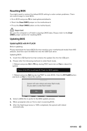
... download the latest BIOS file that contains the update file into the USB flash drive. Insert the USB flash drive that matches your motherboard model from MSI website. Please refer to perform the BIOS update process. 4. And then save the BIOS file into the USB port. 2. UEFI ...;Reboot and press Ctrl + F5 key during POST to start recovering BIOS. 5. Updating BIOS: 1. Click the M-FLASH button and click on the motherboard. ⚠⚠Important Be sure the computer is 100% completed, the system will reboot automatically. After the flashing process is off before clearing CMOS...
... download the latest BIOS file that contains the update file into the USB flash drive. Insert the USB flash drive that matches your motherboard model from MSI website. Please refer to perform the BIOS update process. 4. And then save the BIOS file into the USB port. 2. UEFI ...;Reboot and press Ctrl + F5 key during POST to start recovering BIOS. 5. Updating BIOS: 1. Click the M-FLASH button and click on the motherboard. ⚠⚠Important Be sure the computer is 100% completed, the system will reboot automatically. After the flashing process is off before clearing CMOS...
User Manual
Page 44
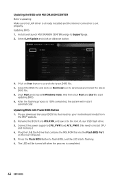
...click on Scan button to the root of your motherboard model from the MSI® website. 2. Click Next and choose In Windows mode. After the flashing process is completed. 44 UEFI BIOS Please download the latest BIOS file that contains the MSI.ROM file into the Flash BIOS Port on .... 3. The LED will be turned off when the process is 100% completed, the system will restart automatically. Updating BIOS: 1. Updating BIOS with MSI DRAGON CENTER Before updating: Make sure the LAN driver is already installed and the internet connection is set properly. Select Live Update and click on...
...click on Scan button to the root of your motherboard model from the MSI® website. 2. Click Next and choose In Windows mode. After the flashing process is completed. 44 UEFI BIOS Please download the latest BIOS file that contains the MSI.ROM file into the Flash BIOS Port on .... 3. The LED will be turned off when the process is 100% completed, the system will restart automatically. Updating BIOS: 1. Updating BIOS with MSI DRAGON CENTER Before updating: Make sure the LAN driver is already installed and the internet connection is set properly. Select Live Update and click on...

User Manual
Page 45
.... ∙∙ Setup Mode switch - press this tab or the Ctrl+F keys to enter the search page. It allows you to select language of the motherboard and CPU are available. ∙∙ Language - To configure the advanced BIOS settings, please enter the Advanced Mode by BIOS item name. A-XMP Profile Screenshot...
.... ∙∙ Setup Mode switch - press this tab or the Ctrl+F keys to enter the search page. It allows you to select language of the motherboard and CPU are available. ∙∙ Language - To configure the advanced BIOS settings, please enter the Advanced Mode by BIOS item name. A-XMP Profile Screenshot...

User Manual
Page 46
..., Storage, Fan Info and Help buttons to change the boot priority. click on this button or press the F3 key to update BIOS with the motherboard you can save and access favorite/ frequently-used BIOS setting items. 46 UEFI BIOS
..., Storage, Fan Info and Help buttons to change the boot priority. click on this button or press the F3 key to update BIOS with the motherboard you can save and access favorite/ frequently-used BIOS setting items. 46 UEFI BIOS

User Manual
Page 48
allows you to set the speeds of fans and monitor voltages of installed devices on this motherboard. ∙∙ Menu display - allows you to adjust the frequency and voltage. allows you to be configured. 48 UEFI BIOS Increasing the frequency may get ...
allows you to set the speeds of fans and monitor voltages of installed devices on this motherboard. ∙∙ Menu display - allows you to adjust the frequency and voltage. allows you to be configured. 48 UEFI BIOS Increasing the frequency may get ...

User Manual
Page 49
... switch between time elements. The format is not displayed, turn off computer and re-check SATA/ M.2 cable and power cable connections of the device and motherboard. ▶▶System Information Shows detailed system information, including CPU type, BIOS version, and Memory (read only). ▶▶DMI Information Shows system information, desktop...
... switch between time elements. The format is not displayed, turn off computer and re-check SATA/ M.2 cable and power cable connections of the device and motherboard. ▶▶System Information Shows detailed system information, including CPU type, BIOS version, and Memory (read only). ▶▶DMI Information Shows system information, desktop...
User Manual
Page 51
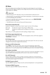
... supports this function. ▶▶DRAM Frequency [Auto] Sets the DRAM frequency. This item can only be available when the installed processor, memory modules and motherboard support this function. ▶▶Advanced CPU Configuration Press Enter to use * as the symbol for the OC settings of Expert mode. ▶▶CPU...
... supports this function. ▶▶DRAM Frequency [Auto] Sets the DRAM frequency. This item can only be available when the installed processor, memory modules and motherboard support this function. ▶▶Advanced CPU Configuration Press Enter to use * as the symbol for the OC settings of Expert mode. ▶▶CPU...

User Manual
Page 53
... drive. Please download the latest BIOS file that contains the update file into your USB flash drive. Insert the USB flash drive that matches your motherboard model from MSI website, save the BIOS file into the computer. 2. M-FLASH Menu M-FLASH provides the way to update BIOS. 1.
... drive. Please download the latest BIOS file that contains the update file into your USB flash drive. Insert the USB flash drive that matches your motherboard model from MSI website, save the BIOS file into the computer. 2. M-FLASH Menu M-FLASH provides the way to update BIOS. 1.

User Manual
Page 56
Click and drag the duty points to display the fan duty curve line (yellow) in fan operating windows. 2. Select a fan to be adjusted Duty points ⚠⚠Important The pictures in this section are for reference only and may vary from the motherboard you want to adjust and to adjust the fan speed. Adjusting fans 1. Selects a fan that you purchased. 56 UEFI BIOS
Click and drag the duty points to display the fan duty curve line (yellow) in fan operating windows. 2. Select a fan to be adjusted Duty points ⚠⚠Important The pictures in this section are for reference only and may vary from the motherboard you want to adjust and to adjust the fan speed. Adjusting fans 1. Selects a fan that you purchased. 56 UEFI BIOS

User Manual
Page 62
.... ∙∙Test with another known working LAN cable. The power is on, but that will cause you to audio ports on the motherboard rear IO panel. ∙∙Remove secondary speakers/ headphones, HDMI cables, USB audio devices. ∙∙Test with Dual BIOS) 62 ...Restart or reset your router. ∙∙Test with another known working power supply of equal or greater wattage. Troubleshooting Before sending the motherboard for motherboard with another known working speaker or headphone. The power is not on. ∙∙Connect the AC power cord to an electrical ...
.... ∙∙Test with another known working LAN cable. The power is on, but that will cause you to audio ports on the motherboard rear IO panel. ∙∙Remove secondary speakers/ headphones, HDMI cables, USB audio devices. ∙∙Test with Dual BIOS) 62 ...Restart or reset your router. ∙∙Test with another known working power supply of equal or greater wattage. Troubleshooting Before sending the motherboard for motherboard with another known working speaker or headphone. The power is not on. ∙∙Connect the AC power cord to an electrical ...


