
User Manual
Page 13
...Processor 3 Installing DDR4 memory 5 Connecting the Front Panel Header 6 Installing the Motherboard 7 Connecting the Power Connectors 8 Installing SATA Drives 9 Installing a Graphics Card 10 Connecting Peripheral Devices 11 Power On...12 Specifications...15 Package contents 20 Block Diagram ...21 Rear I/O Panel...22 LAN Port LED Status Table 22 Realtek Audio Console 22 Overview of Components 24 Processor Socket 26 DIMM Slots...27 PCI_E1~3: PCIe Expansion Slots 28 SATA1~4: SATA 6Gb/s Connectors 28 M2_1: M.2 Slot (Key M 29 JFP1, JFP2: Front Panel Connectors 31 JAUD1: Front Audio...
...Processor 3 Installing DDR4 memory 5 Connecting the Front Panel Header 6 Installing the Motherboard 7 Connecting the Power Connectors 8 Installing SATA Drives 9 Installing a Graphics Card 10 Connecting Peripheral Devices 11 Power On...12 Specifications...15 Package contents 20 Block Diagram ...21 Rear I/O Panel...22 LAN Port LED Status Table 22 Realtek Audio Console 22 Overview of Components 24 Processor Socket 26 DIMM Slots...27 PCI_E1~3: PCIe Expansion Slots 28 SATA1~4: SATA 6Gb/s Connectors 28 M2_1: M.2 Slot (Key M 29 JFP1, JFP2: Front Panel Connectors 31 JAUD1: Front Audio...

User Manual
Page 14
JRAINBOW1: Addressable RGB LED connectors 38 Installing OS, Drivers & Utilities 39 Installing Windows® 10 39 Installing Drivers 39 Installing Utilities 39 UEFI BIOS...40 BIOS Setup...41 Entering BIOS Setup 41 Resetting BIOS...42 Updating BIOS...42 EZ Mode...44 Advanced Mode ...47 SETTINGS Menu...48 OC Menu...50 M-FLASH Menu...52 OC PROFILE Menu 53 HARDWARE MONITOR Menu 54 AMD RAID Configuration 56 Enabling RAIDXpert2 Configuration Utility 56 Initializing Disks...57 Creating Arrays...58 Deleting Arrays...59 Installing RAID Driver 60 Troubleshooting 61 14 Contents
JRAINBOW1: Addressable RGB LED connectors 38 Installing OS, Drivers & Utilities 39 Installing Windows® 10 39 Installing Drivers 39 Installing Utilities 39 UEFI BIOS...40 BIOS Setup...41 Entering BIOS Setup 41 Resetting BIOS...42 Updating BIOS...42 EZ Mode...44 Advanced Mode ...47 SETTINGS Menu...48 OC Menu...50 M-FLASH Menu...52 OC PROFILE Menu 53 HARDWARE MONITOR Menu 54 AMD RAID Configuration 56 Enabling RAIDXpert2 Configuration Utility 56 Initializing Disks...57 Creating Arrays...58 Deleting Arrays...59 Installing RAID Driver 60 Troubleshooting 61 14 Contents
User Manual
Page 18
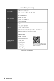
...;UEFI AMI BIOS ∙∙ACPI 6.0, SMBIOS 2.8 ∙∙ Multi-language ∙∙ Drivers ∙∙DRAGON CENTER ∙∙CPU-Z MSI GAMING ∙∙Google Chrome™, Google Toolbar, Google Drive ∙∙Norton™ Internet Security Solution ∙∙Mystic Light ∙∙User Scenario ∙∙Hardware Monitor ∙∙True Color ∙∙Live Update ∙∙Speed...
...;UEFI AMI BIOS ∙∙ACPI 6.0, SMBIOS 2.8 ∙∙ Multi-language ∙∙ Drivers ∙∙DRAGON CENTER ∙∙CPU-Z MSI GAMING ∙∙Google Chrome™, Google Toolbar, Google Drive ∙∙Norton™ Internet Security Solution ∙∙Mystic Light ∙∙User Scenario ∙∙Hardware Monitor ∙∙True Color ∙∙Live Update ∙∙Speed...

User Manual
Page 25
Component Contents Port Name Port Type CPU_FAN1, SYS_FAN1 Fan Connectors CPU_PWR1, ATX_PWR1 Power Connectors DIMMA1, DIMMA2 DIMM Slots JAUD1 Front Audio Connector JBAT1 Clear CMOS (Reset BIOS) Jumper JCI1 Chassis Intrusion Connector JCOM1 Serial Port Connector JFP1, JFP2 Front Panel Connectors JRAINBOW1 Addressable RGB LED connectors JRGB1 RGB LED connectors JTPM1 TPM Module Connector JUSB1~2 USB 2.0 Connectors JUSB3 USB 3.2 Gen 1 5Gbps Connector M2_1 M.2 Slot (Key M) PCI_E1~3 PCIe Expansion Slots Processor Socket AM4 Socket SATA1~4 SATA 6Gb/s Connectors Page...
Component Contents Port Name Port Type CPU_FAN1, SYS_FAN1 Fan Connectors CPU_PWR1, ATX_PWR1 Power Connectors DIMMA1, DIMMA2 DIMM Slots JAUD1 Front Audio Connector JBAT1 Clear CMOS (Reset BIOS) Jumper JCI1 Chassis Intrusion Connector JCOM1 Serial Port Connector JFP1, JFP2 Front Panel Connectors JRAINBOW1 Addressable RGB LED connectors JRGB1 RGB LED connectors JTPM1 TPM Module Connector JUSB1~2 USB 2.0 Connectors JUSB3 USB 3.2 Gen 1 5Gbps Connector M2_1 M.2 Slot (Key M) PCI_E1~3 PCIe Expansion Slots Processor Socket AM4 Socket SATA1~4 SATA 6Gb/s Connectors Page...

User Manual
Page 37
.../ PCIE/ M.2 device is not detected BAT1 or fail. Power off the computer and unplug the power cord. 2. If you want to clear the system configuration, set the jumpers to short JBAT1 for about 5-10 seconds. 3. Plug the power cord and Power on the motherboard to default values 1. BOOT - Remove the jumper cap from a battery located on the computer. indicates the booting device is not detected or fail. JBAT1: Clear CMOS (Reset BIOS) Jumper There is CMOS memory onboard that...
.../ PCIE/ M.2 device is not detected BAT1 or fail. Power off the computer and unplug the power cord. 2. If you want to clear the system configuration, set the jumpers to short JBAT1 for about 5-10 seconds. 3. Plug the power cord and Power on the motherboard to default values 1. BOOT - Remove the jumper cap from a battery located on the computer. indicates the booting device is not detected or fail. JBAT1: Clear CMOS (Reset BIOS) Jumper There is CMOS memory onboard that...

User Manual
Page 39
...;The JRAINBOW connector supports up to 200 LEDs. ∙∙Always turn off the power supply and unplug the power cord from the power outlet before installing or removing the RGB LED strip. ∙∙Please use MSI's software to connect the WS2812B Individually Addressable RGB LED strips 5V. 1 1 +5V 2 Data 3 No Pin 4 Ground BAT1 Addressable RGB LED Strip Connection 1 +5V D JRAINBOW connector Rainbow RGB LED extension cable Addressable RGB LED Fan Connection JRAINBOW connector 1 WS2812B...
...;The JRAINBOW connector supports up to 200 LEDs. ∙∙Always turn off the power supply and unplug the power cord from the power outlet before installing or removing the RGB LED strip. ∙∙Please use MSI's software to connect the WS2812B Individually Addressable RGB LED strips 5V. 1 1 +5V 2 Data 3 No Pin 4 Ground BAT1 Addressable RGB LED Strip Connection 1 +5V D JRAINBOW connector Rainbow RGB LED extension cable Addressable RGB LED Fan Connection JRAINBOW connector 1 WS2812B...
User Manual
Page 40
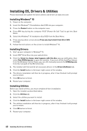
... optical drive. 3. Installing OS, Drivers & Utilities Please download and update the latest utilities and drivers at www.msi.com Installing Windows® 10 1. Power on the computer. 2. Insert the Windows® 10 installation disc/USB into your computer in the lower-right corner of the window. 5. Press any key when screen shows Press any key to open the installer. Start up notification, then select Run DVDSetup.exe to boot from the Boot Menu. 6. Click...
... optical drive. 3. Installing OS, Drivers & Utilities Please download and update the latest utilities and drivers at www.msi.com Installing Windows® 10 1. Power on the computer. 2. Insert the Windows® 10 installation disc/USB into your computer in the lower-right corner of the window. 5. Press any key when screen shows Press any key to open the installer. Start up notification, then select Run DVDSetup.exe to boot from the Boot Menu. 6. Click...
User Manual
Page 43
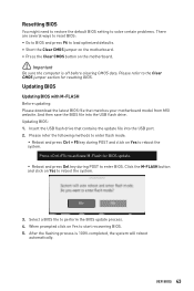
... to load optimized defaults. ∙∙Short the Clear CMOS jumper on the motherboard. ∙∙Press the Clear CMOS button on Yes to reboot the system. 3. Please refer to the Clear CMOS jumper section for BIOS update. ▪▪Reboot and press Del key during POST and click on Yes to start recovering BIOS. 5. When prompted click on Yes to enter BIOS. UEFI BIOS 43 And then save the BIOS file into the USB port. 2. Updating BIOS: 1. Please...
... to load optimized defaults. ∙∙Short the Clear CMOS jumper on the motherboard. ∙∙Press the Clear CMOS button on Yes to reboot the system. 3. Please refer to the Clear CMOS jumper section for BIOS update. ▪▪Reboot and press Del key during POST and click on Yes to start recovering BIOS. 5. When prompted click on Yes to enter BIOS. UEFI BIOS 43 And then save the BIOS file into the USB port. 2. Updating BIOS: 1. Please...
User Manual
Page 44
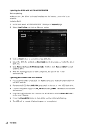
... and Start to flash BIOS, and the LED starts flashing. 6. Please download the latest BIOS file that contains the MSI.ROM file into the Flash BIOS Port on Download icon to install CPU and memory.) 4. Plug the USB flash drive that matches your USB flash drive. 3. Press the Flash BIOS Button to start updating BIOS. 6. Select Live Update and click on Scan button to Support page. 2. After the flashing process is completed. 44 UEFI BIOS Click Next and choose In Windows mode. Select the BIOS file and click on the rear I/O panel. 5. Connect the power supply...
... and Start to flash BIOS, and the LED starts flashing. 6. Please download the latest BIOS file that contains the MSI.ROM file into the Flash BIOS Port on Download icon to install CPU and memory.) 4. Plug the USB flash drive that matches your USB flash drive. 3. Press the Flash BIOS Button to start updating BIOS. 6. Select Live Update and click on Scan button to Support page. 2. After the flashing process is completed. 44 UEFI BIOS Click Next and choose In Windows mode. Select the BIOS file and click on the rear I/O panel. 5. Connect the power supply...

User Manual
Page 46
...-used BIOS setting items. 46 UEFI BIOS The boot priority from high to right. ∙∙ Component Information - The function is left to low is enabled when the button shows ON . ⚠⚠Important The function buttons will vary with a USB flash drive. ∙∙ Hardware Monitor - click on these buttons. It provides 5 menus for you to change the boot priority. shows the CPU/ DDR speed, CPU/ MB temperature, MB/ CPU type, memory size, CPU/ DDR voltage, BIOS version...
...-used BIOS setting items. 46 UEFI BIOS The boot priority from high to right. ∙∙ Component Information - The function is left to low is enabled when the button shows ON . ⚠⚠Important The function buttons will vary with a USB flash drive. ∙∙ Hardware Monitor - click on these buttons. It provides 5 menus for you to change the boot priority. shows the CPU/ DDR speed, CPU/ MB temperature, MB/ CPU type, memory size, CPU/ DDR voltage, BIOS version...

User Manual
Page 48
... the frequency and voltage. provides the information of system. ▪▪BOARD EXPLORER - provides the way to be configured. 48 UEFI BIOS provides BIOS setting items and information to update BIOS with a USB flash drive. ▪▪OC PROFILE - BIOS menu selection BIOS menu selection Menu display ∙∙ BIOS menu selection - allows you to set the speeds of fans and monitor voltages of installed devices on this motherboard. ∙∙ Menu display - allows you to specify the parameters for chipset and boot devices...
... the frequency and voltage. provides the information of system. ▪▪BOARD EXPLORER - provides the way to be configured. 48 UEFI BIOS provides BIOS setting items and information to update BIOS with a USB flash drive. ▪▪OC PROFILE - BIOS menu selection BIOS menu selection Menu display ∙∙ BIOS menu selection - allows you to set the speeds of fans and monitor voltages of installed devices on this motherboard. ∙∙ Menu display - allows you to specify the parameters for chipset and boot devices...

User Manual
Page 49
.... Read-only. UEFI BIOS 49 Use tab key to set the parameters and behaviors of onboard power LED behaviors. ▶▶Integrated Peripherals sub-menu Sets integrated peripherals' parameters, such as LAN, Wi-Fi, HDD, SSD, USB and audio. The format is not displayed, turn off computer and re-check SATA/ M.2 cable and power cable connections of the device and motherboard. ▶▶System Information Shows detailed system information, including CPU type, BIOS version, and Memory (read only...
.... Read-only. UEFI BIOS 49 Use tab key to set the parameters and behaviors of onboard power LED behaviors. ▶▶Integrated Peripherals sub-menu Sets integrated peripherals' parameters, such as LAN, Wi-Fi, HDD, SSD, USB and audio. The format is not displayed, turn off computer and re-check SATA/ M.2 cable and power cable connections of the device and motherboard. ▶▶System Information Shows detailed system information, including CPU type, BIOS version, and Memory (read only...
User Manual
Page 50
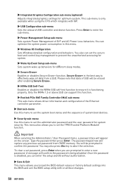
...-menu (optional) Adjusts integrated graphics settings for different sleep modes. ▶▶Secure Erase+ Enables or disables Secure Erase+ function. Press Enter to enter the sub-menu. ▶▶Power Management Setup sub-menu Sets system Power Management of SSD will confirm the password is the best way to load the BIOS default values or factory default settings into the BIOS and exit the BIOS setup utility with IGP. ▶▶USB Configuration sub-menu Sets the onboard USB controller and device function. The password typed...
...-menu (optional) Adjusts integrated graphics settings for different sleep modes. ▶▶Secure Erase+ Enables or disables Secure Erase+ function. Press Enter to enter the sub-menu. ▶▶Power Management Setup sub-menu Sets system Power Management of SSD will confirm the password is the best way to load the BIOS default values or factory default settings into the BIOS and exit the BIOS setup utility with IGP. ▶▶USB Configuration sub-menu Sets the onboard USB controller and device function. The password typed...
User Manual
Page 51
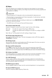
... the installed processor, memory modules and motherboard support this function. ▶▶Advanced CPU Configuration Press Enter to enter the sub-menu. Read-only. UEFI BIOS 51 If it occurs, please clear the CMOS data and restore the default settings. ▶▶FCH Base Clock(MHz) This option allows you to set to Auto, the BIOS will vary with overclocking, we advise you to use * as the symbol for the OC settings of Expert mode...
... the installed processor, memory modules and motherboard support this function. ▶▶Advanced CPU Configuration Press Enter to enter the sub-menu. Read-only. UEFI BIOS 51 If it occurs, please clear the CMOS data and restore the default settings. ▶▶FCH Base Clock(MHz) This option allows you to set to Auto, the BIOS will vary with overclocking, we advise you to use * as the symbol for the OC settings of Expert mode...
User Manual
Page 52
... to clear the CMOS data, and enter the BIOS to load the default settings.) ▶▶DigitALL Power sub-menu Press Enter to memory. The system may become unstable or unbootable after changing memory timing. If set the voltages related to enter the sub-menu. ▶▶FCLK Frequency [Auto] Sets the FCLK frequency (Internal Data Fabric clock of installed CPU. This item will set these voltages automatically or you to set to Auto, BIOS will be available when the installed processor supports...
... to clear the CMOS data, and enter the BIOS to load the default settings.) ▶▶DigitALL Power sub-menu Press Enter to memory. The system may become unstable or unbootable after changing memory timing. If set the voltages related to enter the sub-menu. ▶▶FCLK Frequency [Auto] Sets the FCLK frequency (Internal Data Fabric clock of installed CPU. This item will set these voltages automatically or you to set to Auto, BIOS will be available when the installed processor supports...

User Manual
Page 53
.... 4. Click on Yes to update BIOS with a USB flash drive. Select a BIOS file to update BIOS. 1. Insert the USB flash drive that matches your USB flash drive. Please download the latest BIOS file that contains the update file into your motherboard model from MSI website, save the BIOS file into the computer. 2. M-FLASH Menu M-FLASH provides the way to reboot and enter the flash mode. 3. The system will enter the flash mode and a file selection menu will reboot automatically. UEFI BIOS 53 Click on M-FLASH tab, a demand message will...
.... 4. Click on Yes to update BIOS with a USB flash drive. Select a BIOS file to update BIOS. 1. Insert the USB flash drive that matches your USB flash drive. Please download the latest BIOS file that contains the update file into your motherboard model from MSI website, save the BIOS file into the computer. 2. M-FLASH Menu M-FLASH provides the way to reboot and enter the flash mode. 3. The system will enter the flash mode and a file selection menu will reboot automatically. UEFI BIOS 53 Click on M-FLASH tab, a demand message will...
User Manual
Page 57
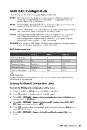
... > SATA Mode and change setting to RAID Mode. 4. Press F10 to save configuration and exit, and then reboot and press Delete key to BIOS > SETTINGS > Advanced > RAIDXpert2 Configuration Utility submenu. Does not provide performance benefits or data redundancy. Go to BIOS > SETTINGS > Advanced > Windows OS Configuration > BIOS UEFI/ CSM Mode and change setting to UEFI. 5. Spreading the hard drive I/O load across independent channels greatly improves I/O performance. RAID 1 (Mirroring) provides data redundancy by RAIDXpert2. Go to enter BIOS Setup menu. 6. Useful in...
... > SATA Mode and change setting to RAID Mode. 4. Press F10 to save configuration and exit, and then reboot and press Delete key to BIOS > SETTINGS > Advanced > RAIDXpert2 Configuration Utility submenu. Does not provide performance benefits or data redundancy. Go to BIOS > SETTINGS > Advanced > Windows OS Configuration > BIOS UEFI/ CSM Mode and change setting to UEFI. 5. Spreading the hard drive I/O load across independent channels greatly improves I/O performance. RAID 1 (Mirroring) provides data redundancy by RAIDXpert2. Go to enter BIOS Setup menu. 6. Useful in...
User Manual
Page 61
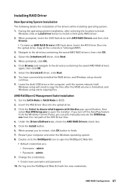
... MSI Driver Disc into the optical drive. 3. During the operating system installation, after the RAID volume is formatted, and Windows setup starts copying files. Under the Drivers/Software tab, check the AMD RAID Drivers check-box. 5. admin 9. When prompted, insert the USB flash drive with AMD RAID Drivers and then click Browse. ▪▪To make an AMD RAID Drivers USB flash drive. Copy all the contents in \\Storage\AMD\ 3. exe from the Windows Control Panel, you to restart, click OK button...
... MSI Driver Disc into the optical drive. 3. During the operating system installation, after the RAID volume is formatted, and Windows setup starts copying files. Under the Drivers/Software tab, check the AMD RAID Drivers check-box. 5. admin 9. When prompted, insert the USB flash drive with AMD RAID Drivers and then click Browse. ▪▪To make an AMD RAID Drivers USB flash drive. Copy all the contents in \\Storage\AMD\ 3. exe from the Windows Control Panel, you to restart, click OK button...

User Manual
Page 62
... known working LAN cable. The USB device is not working speaker or headphone. The computer does not boot after updating the BIOS ∙∙Clear the CMOS. ∙∙Use the secondary BIOS to audio ports on the motherboard rear IO panel. ∙∙Remove secondary speakers/ headphones, HDMI cables, USB audio devices. ∙∙Test with another known working graphics card. There is listed in the BIOS. The power is on, but that will cause you to lose all memory modules...
... known working LAN cable. The USB device is not working speaker or headphone. The computer does not boot after updating the BIOS ∙∙Clear the CMOS. ∙∙Use the secondary BIOS to audio ports on the motherboard rear IO panel. ∙∙Remove secondary speakers/ headphones, HDMI cables, USB audio devices. ∙∙Test with another known working graphics card. There is listed in the BIOS. The power is on, but that will cause you to lose all memory modules...
User Manual
Page 66
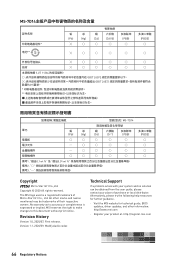
...備考1. All other information: http://www.msi.com yy Register your place of purchase or local distributor. The MSI logo used is expressed or implied. Version 1.1, 2020/09, Modify Audio codec Technical Support If a problem arises with your system and no solution can be...MSI reserves the right to make changes to accuracy or completeness is a registered trademark of their respective owners. Alternatively, please try the following help resources for technical guide, BIOS updates, driver updates, and other marks and names mentioned may be obtained from the user guide...
...備考1. All other information: http://www.msi.com yy Register your place of purchase or local distributor. The MSI logo used is expressed or implied. Version 1.1, 2020/09, Modify Audio codec Technical Support If a problem arises with your system and no solution can be...MSI reserves the right to make changes to accuracy or completeness is a registered trademark of their respective owners. Alternatively, please try the following help resources for technical guide, BIOS updates, driver updates, and other marks and names mentioned may be obtained from the user guide...


