User Guide
Page 8
Hardware Setup 2-1 Quick Components Guide 2-2 CPU (Central Processing Unit 2-2 Introduction to LGA 775 CPU 2-3 CPU & Cooler Installation 2-5 Memory ...2-6 Introduction to DDRII SDRAM 2-7 Memory Module Population Rules 2-7 Installing DDRII Modules 2-8 Power Supply ...2-8 ATX 24-Pin Power Connector: ATX 2-9 ATX 12V Power Connector: JPW/ JPWR 2-9 IEEE 1394 Port (optional 2-10 Mouse/Keyboard Connector 2-11 Back Panel ...2-11 Serial Port...
Hardware Setup 2-1 Quick Components Guide 2-2 CPU (Central Processing Unit 2-2 Introduction to LGA 775 CPU 2-3 CPU & Cooler Installation 2-5 Memory ...2-6 Introduction to DDRII SDRAM 2-7 Memory Module Population Rules 2-7 Installing DDRII Modules 2-8 Power Supply ...2-8 ATX 24-Pin Power Connector: ATX 2-9 ATX 12V Power Connector: JPW/ JPWR 2-9 IEEE 1394 Port (optional 2-10 Mouse/Keyboard Connector 2-11 Back Panel ...2-11 Serial Port...

User Guide
Page 13
... data transfers at up Supported FSB - 1066/ 800/ 533 MHz Chipset - Supports PIO, Bus Master operation mode SATA - Supports 3/4 pin CPU Fan Pin-Header with jack sensing - North Bridge: Intel® 975X chipset - DDRII 533/667/800 SDRAM (8GB Max) - 4 DIMMs DDRII (240pin / 1.8V) LAN - Chip integrated by Realtek® ALC882M - Supports...
... data transfers at up Supported FSB - 1066/ 800/ 533 MHz Chipset - Supports PIO, Bus Master operation mode SATA - Supports 3/4 pin CPU Fan Pin-Header with jack sensing - North Bridge: Intel® 975X chipset - DDRII 533/667/800 SDRAM (8GB Max) - 4 DIMMs DDRII (240pin / 1.8V) LAN - Chip integrated by Realtek® ALC882M - Supports...
User Guide
Page 14
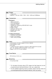
... x1 slots - 2 PCI slots. - 1 orange slot which supports 2 masters for MSI special PCI function card (ex. Support 3.3V/ 5V PCI bus Interface Form Factor - ATX (30.4cm X 24.5 cm) Mounting - 9 mounting holes * For the latest information about CPU, please visit http://www.msi.com.tw/ program/products/mainboard/mbd/pro_mbd_cpu_support.php ** For the updated...
... x1 slots - 2 PCI slots. - 1 orange slot which supports 2 masters for MSI special PCI function card (ex. Support 3.3V/ 5V PCI bus Interface Form Factor - ATX (30.4cm X 24.5 cm) Mounting - 9 mounting holes * For the latest information about CPU, please visit http://www.msi.com.tw/ program/products/mainboard/mbd/pro_mbd_cpu_support.php ** For the updated...

User Guide
Page 17
While doing the installation, be careful in holding the components and follow the installation procedures. Chapter 2 Hardware Setup This chapter tells you how to install the CPU, memory modules, and expansion cards, as well as how to setup the jumpers on connecting the peripheral devices, such as the mouse, keyboard, etc. Also, it provides the instructions on the mainboard.
While doing the installation, be careful in holding the components and follow the installation procedures. Chapter 2 Hardware Setup This chapter tells you how to install the CPU, memory modules, and expansion cards, as well as how to setup the jumpers on connecting the peripheral devices, such as the mouse, keyboard, etc. Also, it provides the instructions on the mainboard.
User Guide
Page 19
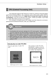
... While replacing the CPU, always turn off the ATX power supply or unplug the power supply's power cord from overheating. 2. Always make sure to install the cooler to ensure the safety of heat sink paste (or thermal tape) between the CPU and the heatsink to protect the CPU from the grounded ...to purchase and install them before turning on it for better heat dispersion. If you apply an even layer of CPU. For the latest information about CPU, please visit http://www.msi.com.tw/program/ produc ts /mainboar d/mbd/pr o_mbd_c pu _s upport .php. Alignment Key Alignment Key ...
... While replacing the CPU, always turn off the ATX power supply or unplug the power supply's power cord from overheating. 2. Always make sure to install the cooler to ensure the safety of heat sink paste (or thermal tape) between the CPU and the heatsink to protect the CPU from the grounded ...to purchase and install them before turning on it for better heat dispersion. If you apply an even layer of CPU. For the latest information about CPU, please visit http://www.msi.com.tw/program/ produc ts /mainboar d/mbd/pr o_mbd_c pu _s upport .php. Alignment Key Alignment Key ...

User Guide
Page 20
...heat dispersion. Align the two pin 1 indicators (the triangles on the CPU & the CPU Clip), and use the CPU Clip to clip the CPU up, pressing the clips on the bottom to touch the pins. 4. If you are installing the CPU, make the pin 1 indicator (yellow triangle) in the left-bottom ...corner). land side cover 3. The availability of your CPU cooler is firmly installed before installing the heat sink/cooler fan for the same direction as the arrows shown. MS-7246 Mainboard CPU & Cooler Installation (CPU clip is in the leftbottom corner. 2. Follow the steps below to...
...heat dispersion. Align the two pin 1 indicators (the triangles on the CPU & the CPU Clip), and use the CPU Clip to clip the CPU up, pressing the clips on the bottom to touch the pins. 4. If you are installing the CPU, make the pin 1 indicator (yellow triangle) in the left-bottom ...corner). land side cover 3. The availability of your CPU cooler is firmly installed before installing the heat sink/cooler fan for the same direction as the arrows shown. MS-7246 Mainboard CPU & Cooler Installation (CPU clip is in the leftbottom corner. 2. Follow the steps below to...

User Guide
Page 21
...Setup 5. The CPU has a plastic cap on it to protect the socket pin. 6. Use your index finger to allow the whole module to the hook of the socket. 9. Before you have installed the CPU, always cover it to release the CPU, then press down the CPU with the CPU chamfer, and the... square on the CPU socket. 2-5 Correctly align the triangle of socket reveal. 7. The CPU is installed well on the CPU Clip to be installed onto the CPU socket. 10. The pins of CPU Clip with...
...Setup 5. The CPU has a plastic cap on it to protect the socket pin. 6. Use your index finger to allow the whole module to the hook of the socket. 9. Before you have installed the CPU, always cover it to release the CPU, then press down the CPU with the CPU chamfer, and the... square on the CPU socket. 2-5 Correctly align the triangle of socket reveal. 7. The CPU is installed well on the CPU Clip to be installed onto the CPU socket. 10. The pins of CPU Clip with...

User Guide
Page 22
... lightly onto the load plate, and then secure the lever with 2 fingers. Press the four hooks down to lock the hooks. Visually inspect if the CPU is seated well into the holes of the mainboard. 14. Press down the cooler until its four clips get wedged into the socket, then remove... the CPU Clip with the hook under retention tab. 13. Then rotate the locking switch (refer to the correct direction marked on the mainboard with the plastic...
... lightly onto the load plate, and then secure the lever with 2 fingers. Press the four hooks down to lock the hooks. Visually inspect if the CPU is seated well into the holes of the mainboard. 14. Press down the cooler until its four clips get wedged into the socket, then remove... the CPU Clip with the hook under retention tab. 13. Then rotate the locking switch (refer to the correct direction marked on the mainboard with the plastic...
User Guide
Page 25
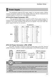
...+12V 1 JPWR JPWR Pin Definition PIN SIGNAL 1 5V 2 GND 3 GND 4 12V Important 1. ATX 24-Pin Power Connector: ATX This connector allows you to the CPU. Hardware Setup Power Supply The mainboard supports ATX power supply for system stability. 3. Before inserting the power supply connector, always make sure the plug ...) is used to provide power to ensure stable operation of the mainboard. 2. Then push down the power supply firmly into the connector. 13 ATX 24 Pin Definition 1 PIN SIGNAL PIN SIGNAL 1 +3.3V 13 +3.3V 2 +3.3V 14 -12V 3 GND 15 GND 4 +5V 16 PS...
...+12V 1 JPWR JPWR Pin Definition PIN SIGNAL 1 5V 2 GND 3 GND 4 12V Important 1. ATX 24-Pin Power Connector: ATX This connector allows you to the CPU. Hardware Setup Power Supply The mainboard supports ATX power supply for system stability. 3. Before inserting the power supply connector, always make sure the plug ...) is used to provide power to ensure stable operation of the mainboard. 2. Then push down the power supply firmly into the connector. 13 ATX 24 Pin Definition 1 PIN SIGNAL PIN SIGNAL 1 +3.3V 13 +3.3V 2 +3.3V 14 -12V 3 GND 15 GND 4 +5V 16 PS...
User Guide
Page 30
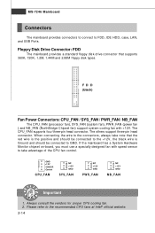
...Please refer to FDD, IDE HDD, case, LAN, and USB Ports. MS-7246 Mainboard Connectors The mainboard provides connectors to connect to the recommended CPU fans at Intel® official website. 2-14 The CPU_FAN supports four/three-pin head connector. The others support three-pin head connector. FD D...speed sensor to take note that supports 360K, 720K, 1.2M, 1.44M and 2.88M floppy disk types. Always consult the vendors for proper CPU cooling fan. 2. Floppy Disk Drive Connector: FDD The mainboard provides a standard floppy disk drive connector that the red wire is the positive and...
...Please refer to FDD, IDE HDD, case, LAN, and USB Ports. MS-7246 Mainboard Connectors The mainboard provides connectors to connect to the recommended CPU fans at Intel® official website. 2-14 The CPU_FAN supports four/three-pin head connector. The others support three-pin head connector. FD D...speed sensor to take note that supports 360K, 720K, 1.2M, 1.44M and 2.88M floppy disk types. Always consult the vendors for proper CPU cooling fan. 2. Floppy Disk Drive Connector: FDD The mainboard provides a standard floppy disk drive connector that the red wire is the positive and...
User Guide
Page 37
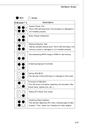
... RTC (Real Time Clock) Initializing Video Interface This will start writing VGA sign-on message to RAM for fast booting. The D-LED will start detecting CPU clock, checking type of video onboard. Testing VGA BIOS This will hang if the memory module is damaged or 3 4 not installed properly.
... RTC (Real Time Clock) Initializing Video Interface This will start writing VGA sign-on message to RAM for fast booting. The D-LED will start detecting CPU clock, checking type of video onboard. Testing VGA BIOS This will hang if the memory module is damaged or 3 4 not installed properly.
User Guide
Page 47
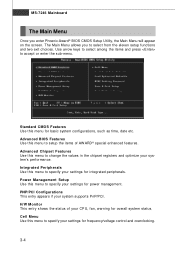
... CMOS Features Use this menu to setup the items of your settings for overall system status. Advanced Chipset Features Use this menu to specify your CPU, fan, warning for integrated peripherals. Power Management Setup Use this menu to specify your system supports PnP/PCI. Advanced BIOS Features Use this menu for...
... CMOS Features Use this menu to setup the items of your settings for overall system status. Advanced Chipset Features Use this menu to specify your CPU, fan, warning for integrated peripherals. Power Management Setup Use this menu to specify your system supports PnP/PCI. Advanced BIOS Features Use this menu for...
User Guide
Page 50
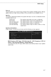
... Drive A This item allows you to enter the sub-menu and the following screen appears: BIOS Version/ CPU Type/ CPU ID/uCode ID / CPU Frequency/ CPU L2 Cache/ Total Physical M emory/ Usage M emory The items show the CPU type, BIOS version and memory status of floppy drive installed. Halt On The setting determines whether the...
... Drive A This item allows you to enter the sub-menu and the following screen appears: BIOS Version/ CPU Type/ CPU ID/uCode ID / CPU Frequency/ CPU L2 Cache/ Total Physical M emory/ Usage M emory The items show the CPU type, BIOS version and memory status of floppy drive installed. Halt On The setting determines whether the...
User Guide
Page 51
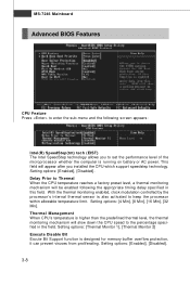
...can prevent viruses from proliferating. Setting options: [4 Min], [8 Min], [16 Min], [32 Min]. Delay Prior to Thermal W hen the CPU temperature reaches a factory preset level, a thermal monitoring mechanism will be enabled following screen appears: Intel(R) SpeedStep(tm) tech (EIST) The Intel ... microprocessor whether the computer is higher than the predefined thermal level, the thermal monitoring mechanism will appear after you installed the CPU which support speedstep technology. Setting options: [Thermal Monitor 1], [Thermal Monitor 2] Execute Disable Bit Excute Bit Support function is...
...can prevent viruses from proliferating. Setting options: [4 Min], [8 Min], [16 Min], [32 Min]. Delay Prior to Thermal W hen the CPU temperature reaches a factory preset level, a thermal monitoring mechanism will be enabled following screen appears: Intel(R) SpeedStep(tm) tech (EIST) The Intel ... microprocessor whether the computer is higher than the predefined thermal level, the thermal monitoring mechanism will appear after you installed the CPU which support speedstep technology. Setting options: [Thermal Monitor 1], [Thermal Monitor 2] Execute Disable Bit Excute Bit Support function is...

User Guide
Page 59
... in this section are : [S1 (POS)] The S1 sleep mode is a lower power state where the information of this state, no system context is lost (CPU or chipset) and hardware maintains all system context. [S3 (STR)] The S3 sleep mode is a low power state. If your operating system supports ACPI, such...
... in this section are : [S1 (POS)] The S1 sleep mode is a lower power state where the information of this state, no system context is lost (CPU or chipset) and hardware maintains all system context. [S3 (STR)] The S3 sleep mode is a low power state. If your operating system supports ACPI, such...

User Guide
Page 60
.... Restore on PME (Power Management Event). Resume by USB The item allows the activity of the USB device to [Enabled], this field, all devices except CPU will reboot after a power failure or interrupt occurs. Setting options: [Power Off] The power button functions as normal power off button. [Suspend] W hen you press...
.... Restore on PME (Power Management Event). Resume by USB The item allows the activity of the USB device to [Enabled], this field, all devices except CPU will reboot after a power failure or interrupt occurs. Setting options: [Power Off] The power button functions as normal power off button. [Suspend] W hen you press...

User Guide
Page 62
... the PCI Graphic card first. Init Display First This setting specifies which allows I/O devices to operate at speeds nearing the speed the CPU itself uses when communicating with its special components. If a PCI Graphic card is only directed to Enabled, multiple VGA devices operating on... VGA device's palette registers, permitting the palette registers of palette registers on every video device. Enabled Data read or written by the CPU is your primary graphics adapter. This section covers some very technical items and it is disabled). PCI, or Peripheral Component Interconnect, is...
... the PCI Graphic card first. Init Display First This setting specifies which allows I/O devices to operate at speeds nearing the speed the CPU itself uses when communicating with its special components. If a PCI Graphic card is only directed to Enabled, multiple VGA devices operating on... VGA device's palette registers, permitting the palette registers of palette registers on every video device. Enabled Data read or written by the CPU is your primary graphics adapter. This section covers some very technical items and it is disabled). PCI, or Peripheral Component Interconnect, is...
User Guide
Page 64
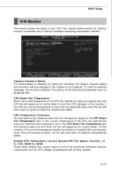
...recording the chassis intrusion status and issuing a warning message if the chassis is once opened. If the current temperature of the CPU fan reaches the value you set temperatures minus the tolerance value), the fan will automatically return to [Enabled] later. To ...BIOS Setup H/W Monitor This section shows the status of the monitored hardware devices/ components such as CPU voltage, temperatures and all of your CPU, fan, overall system status, etc. System/CPU Temperature, Current System/CPU Fan Speed, Vcore(V), +5 V, +12V, VBAT(V), 5VSB These items display the current status of ...
...recording the chassis intrusion status and issuing a warning message if the chassis is once opened. If the current temperature of the CPU fan reaches the value you set temperatures minus the tolerance value), the fan will automatically return to [Enabled] later. To ...BIOS Setup H/W Monitor This section shows the status of the monitored hardware devices/ components such as CPU voltage, temperatures and all of your CPU, fan, overall system status, etc. System/CPU Temperature, Current System/CPU Fan Speed, Vcore(V), +5 V, +12V, VBAT(V), 5VSB These items display the current status of ...
User Guide
Page 65
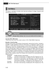
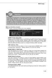
... low load balance, it will be powered only when users' PC need to be boosted up CPU automatically to adjust the best CPU frequency automatically. W hen the motherboard detects CPU is temporarily suspending or staying in Cell Menu includes some important settings of data like 3D games... or the video process, and the CPU frequency need to run smoothly and faster. When the CPU is running programs,...
... low load balance, it will be powered only when users' PC need to be boosted up CPU automatically to adjust the best CPU frequency automatically. W hen the motherboard detects CPU is temporarily suspending or staying in Cell Menu includes some important settings of data like 3D games... or the video process, and the CPU frequency need to run smoothly and faster. When the CPU is running programs,...
User Guide
Page 66
... synchronous DRAM is controlled by BIOS based on the configurations on the DRAM module. Setting options: [2], [3], [4], [5], [6], [Auto]. We suggest user to make sure that your CPU can afford to configure following fields manually. If you find the PC appears to lower the level of cycles for the RAS to accumulate its...
... synchronous DRAM is controlled by BIOS based on the configurations on the DRAM module. Setting options: [2], [3], [4], [5], [6], [Auto]. We suggest user to make sure that your CPU can afford to configure following fields manually. If you find the PC appears to lower the level of cycles for the RAS to accumulate its...

