
User Manual
Page 4
... has been exposed to the power inlet. 7. iv com.tw/program/service/faq/faq/esc_faq_list.php h Contact our technical staff at: support@msi.com.tw Safety Instructions 1. CAUTION: Danger of the power source and adjust properly 110/220V be noted. 10. h Visit the...cause electrical shock. 11. h The equipment has obvious sign of the following help resources for technical guide, BIOS updates, driver updates, and other information: http://www.msi.com.tw & http://www.msi. The openings on the equipment should be - fore connecting the equipment to moisture. h The equipment has dropped...
... has been exposed to the power inlet. 7. iv com.tw/program/service/faq/faq/esc_faq_list.php h Contact our technical staff at: support@msi.com.tw Safety Instructions 1. CAUTION: Danger of the power source and adjust properly 110/220V be noted. 10. h Visit the...cause electrical shock. 11. h The equipment has obvious sign of the following help resources for technical guide, BIOS updates, driver updates, and other information: http://www.msi.com.tw & http://www.msi. The openings on the equipment should be - fore connecting the equipment to moisture. h The equipment has dropped...

User Manual
Page 5
Getting Started F-1-3 2. BIOS Setup F-3-1 German version ...G-1 v BIOS Setup E-3-1 French version F-1-1 1. CONTENTS FCC-B Radio Frequency Interference Statement ii Copyright Notice ...iii Revision History ...iii Safety Instructions ...iv Technical Support ...iv English version E-1-1 1. Getting Started E-1-3 2. Hardware Setup E-2-1 3. Hardware Setup F-2-1 3.
Getting Started F-1-3 2. BIOS Setup F-3-1 German version ...G-1 v BIOS Setup E-3-1 French version F-1-1 1. CONTENTS FCC-B Radio Frequency Interference Statement ii Copyright Notice ...iii Revision History ...iii Safety Instructions ...iv Technical Support ...iv English version E-1-1 1. Getting Started E-1-3 2. Hardware Setup E-2-1 3. Hardware Setup F-2-1 3.
User Manual
Page 10
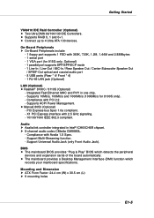
... with PCI 2.2. - Supports 10Mb/s, 100Mb/s and 1000Mb/s (1000Mb/s for 915G only, Optional) - 1 parallel port supports SPP/EPP/ECP mode - ...) h Realtek® 8100C / 8110S (Optional) - h Marvell 8053 (Optional) - BIOS h The mainboard BIOS provides "Plug & Play" BIOS which records your mainboard specifications. Supports ACPI Power Management. X1 PCI Express interface with Azalia ...Support Universal Audio Jack (only Front Audio Jack). h Supports RAID 0, 1 and 0+1. Mounting and Dimension h ATX Form Factor: 24.4 cm (W) x 30.5 cm (L) h 9 mounting holes E1-5 Compliance with 360K, 720K...
... with PCI 2.2. - Supports 10Mb/s, 100Mb/s and 1000Mb/s (1000Mb/s for 915G only, Optional) - 1 parallel port supports SPP/EPP/ECP mode - ...) h Realtek® 8100C / 8110S (Optional) - h Marvell 8053 (Optional) - BIOS h The mainboard BIOS provides "Plug & Play" BIOS which records your mainboard specifications. Supports ACPI Power Management. X1 PCI Express interface with Azalia ...Support Universal Audio Jack (only Front Audio Jack). h Supports RAID 0, 1 and 0+1. Mounting and Dimension h ATX Form Factor: 24.4 cm (W) x 30.5 cm (L) h 9 mounting holes E1-5 Compliance with 360K, 720K...

User Manual
Page 11
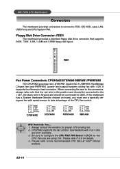
... Out JPW1 N B FA N1 PCI_E1 PCI_E2 BIOS JCD1 CMI 9880L J AUD 1 PCI_E3 PCI 1 PCI 2 PCI 3 Intel 915P/G B AT T + SATA2 SATA4 SATA1 SATA3 IDE1 J B AT 1 JUSB1 ICH6/ ICH6R S YS FAN 1 VIA VT6410 IDE 2 IDE 3 JUSB2 JDB1 JFP2 JFP1 ATX1 915P/G Combo (MS-7058) v1.X ATX Mainboard E1-6 7058 ATX Mainboard Mainboard Layout W in bo nd...
... Out JPW1 N B FA N1 PCI_E1 PCI_E2 BIOS JCD1 CMI 9880L J AUD 1 PCI_E3 PCI 1 PCI 2 PCI 3 Intel 915P/G B AT T + SATA2 SATA4 SATA1 SATA3 IDE1 J B AT 1 JUSB1 ICH6/ ICH6R S YS FAN 1 VIA VT6410 IDE 2 IDE 3 JUSB2 JDB1 JFP2 JFP1 ATX1 915P/G Combo (MS-7058) v1.X ATX Mainboard E1-6 7058 ATX Mainboard Mainboard Layout W in bo nd...
User Manual
Page 25
... positive and should be connected to the +12V, the black wire is Ground and should be connected to configure the CPU FAN PIN Select in BIOS for the CPU Fan you must use a specially designed fan with 3 or 4 fins are using first. Please refer to FDD, IDE HDD, case, LAN,...E2-14 CPUFAN2 supports the fan control. GND +12V Sensor Control CPUFAN2 GND +12V NC SYSFAN1 GND +12V NC PWRFAN1 GND +12V Sensor NBFAN1 MSI Reminds You... 1. Be sure to GND. MS-7058 ATX Mainboard Connectors The mainboard provides connectors to connect to the recommended CPU fans at Intel® official website.
... positive and should be connected to the +12V, the black wire is Ground and should be connected to configure the CPU FAN PIN Select in BIOS for the CPU Fan you must use a specially designed fan with 3 or 4 fins are using first. Please refer to FDD, IDE HDD, case, LAN,...E2-14 CPUFAN2 supports the fan control. GND +12V Sensor Control CPUFAN2 GND +12V NC SYSFAN1 GND +12V NC PWRFAN1 GND +12V Sensor NBFAN1 MSI Reminds You... 1. Be sure to GND. MS-7058 ATX Mainboard Connectors The mainboard provides connectors to connect to the recommended CPU fans at Intel® official website.

User Manual
Page 29
...Port 1 - Right channel 6 SENSE1_RETIRN Jack detection return from front panel JACK1 7 SENSE_SEND Jack detection sense line from front panel JACK2 E2-18 signals BIOS that a High Definition Audio dongle is compliant with Intel® Front Panel I/O Connectivity Design Guide. 2 1 10 9 JAUD2 JAUD2 Pin Definition ... The JAUD2 front panel audio connector allows you to connect to the front panel audio and is connected to the analog header. MS-7058 ATX Mainboard CD-In Connector: JCD1 The connector is connected. 5 PORT 2R Analog Port 2 - PRESENCE# = 0 when a High Definition Audio...
...Port 1 - Right channel 6 SENSE1_RETIRN Jack detection return from front panel JACK1 7 SENSE_SEND Jack detection sense line from front panel JACK2 E2-18 signals BIOS that a High Definition Audio dongle is compliant with Intel® Front Panel I/O Connectivity Design Guide. 2 1 10 9 JAUD2 JAUD2 Pin Definition ... The JAUD2 front panel audio connector allows you to connect to the front panel audio and is connected to the analog header. MS-7058 ATX Mainboard CD-In Connector: JCD1 The connector is connected. 5 PORT 2R Analog Port 2 - PRESENCE# = 0 when a High Definition Audio...

User Manual
Page 30
... NC GND IRRX Front USB Connectors: JUSB1 & JUSB2 The mainboard provides two standard USB 2.0 pin headers JUSB1 & JUSB2 . You must configure the setting through the BIOS setup to JUSB1 or JUSB2 USB 2.0 Bracket E2-19 Hardware Setup IrDA Infrared Module Header: JIR1 The connector allows you to connect to IrDA Infrared...
... NC GND IRRX Front USB Connectors: JUSB1 & JUSB2 The mainboard provides two standard USB 2.0 pin headers JUSB1 & JUSB2 . You must configure the setting through the BIOS setup to JUSB1 or JUSB2 USB 2.0 Bracket E2-19 Hardware Setup IrDA Infrared Module Header: JIR1 The connector allows you to connect to IrDA Infrared...
User Manual
Page 31
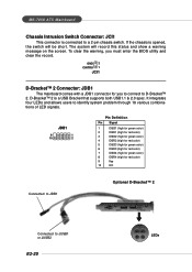
... for red color) 5 DBG3 (high for green color) 6 DBR3 (high for red color) 7 DBG4 (high for green color) 8 DBR4 (high for you must enter the BIOS utility and clear the record. To clear the warning, you to connect to a 2-pin chassis switch. D-Bracket™ 2 is opened, the switch will record this... chassis is a USB Bracket that supports both USB1.1 & 2.0 spec. It integrates four LEDs and allows users to JUSB1 or JUSB2 E2-20 LEDs MS-7058 ATX Mainboard Chassis Intrusion Switch Connector: JCI1 This connector is connected to D-Bracket™ 2.
... for red color) 5 DBG3 (high for green color) 6 DBR3 (high for red color) 7 DBG4 (high for green color) 8 DBR4 (high for you must enter the BIOS utility and clear the record. To clear the warning, you to connect to a 2-pin chassis switch. D-Bracket™ 2 is opened, the switch will record this... chassis is a USB Bracket that supports both USB1.1 & 2.0 spec. It integrates four LEDs and allows users to JUSB1 or JUSB2 E2-20 LEDs MS-7058 ATX Mainboard Chassis Intrusion Switch Connector: JCI1 This connector is connected to D-Bracket™ 2.
User Manual
Page 33
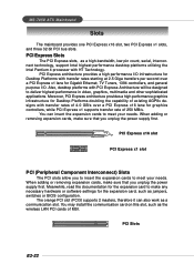
...of 4.0 GB/s over a PCI Express x1 lane for the expansion card to meet your needs. You can also work as jumpers, switches or BIOS configuration. PCI Express x16 slot PCI Express x1 slot PCI (Peripheral Component Interconnect) Slots The PCI slots allow you to insert the expansion cards ...adding or removing expansion cards, make any necessary hardware or software settings for graphics controllers, while PCI Express x1 supports transfer rate of MSI. MS-7058 ATX Mainboard Slots The mainboard provides one PCI Express x16 slot, two PCI Express x1 slots, and three 32-bit PCI bus slots. PCI...
...of 4.0 GB/s over a PCI Express x1 lane for the expansion card to meet your needs. You can also work as jumpers, switches or BIOS configuration. PCI Express x16 slot PCI Express x1 slot PCI (Peripheral Component Interconnect) Slots The PCI slots allow you to insert the expansion cards ...adding or removing expansion cards, make any necessary hardware or software settings for graphics controllers, while PCI Express x1 supports transfer rate of MSI. MS-7058 ATX Mainboard Slots The mainboard provides one PCI Express x16 slot, two PCI Express x1 slots, and three 32-bit PCI bus slots. PCI...

User Manual
Page 35
...” You want to the date this chapter are under each BIOS category described in the 1st line appearing after the memory count. MSI Reminds You... 1. BIOS Setup Chapter 3. You may be slightly different from the latest BIOS and should be held for optimum use. V1.0BH refers to the... BIOS version. 04/23/04 refers to change the default settings for better...
...” You want to the date this chapter are under each BIOS category described in the 1st line appearing after the memory count. MSI Reminds You... 1. BIOS Setup Chapter 3. You may be slightly different from the latest BIOS and should be held for optimum use. V1.0BH refers to the... BIOS version. 04/23/04 refers to change the default settings for better...

User Manual
Page 36
MS-7058 ATX Mainboard Entering Setup Power on the computer and the system will boot from by simultaneously pressing , , ...Recovery If the message disappears before you respond and you still wish to select the 1st boot device without entering the BIOS setup utility by turning it will still use the original first boot device to boot from the selected device. The POST... messages might pass by too quickly for you to respond in the BIOS setup utility, so next time when you want to boot up. Select the one you power on the system, ...
MS-7058 ATX Mainboard Entering Setup Power on the computer and the system will boot from by simultaneously pressing , , ...Recovery If the message disappears before you respond and you still wish to select the 1st boot device without entering the BIOS setup utility by turning it will still use the original first boot device to boot from the selected device. The POST... messages might pass by too quickly for you to respond in the BIOS setup utility, so next time when you want to boot up. Select the one you power on the system, ...

User Manual
Page 37
... returns to the main menu from the latest BIOS and should be held for the selected setup category is the Main Menu. BIOS Setup Control Keys Enter> Move to the previous... entering the Setup utility, the first screen you see is displayed at the bottom of the BIOS setup program provide optimal performance settings for better system performance. You can use the arrow keys ...8593;↓ ) to select the item. Main Menu The main menu displays the setup categories the BIOS supplies. Therefore, the description may be slightly different from a submenu Increase the numeric value or make...
... returns to the main menu from the latest BIOS and should be held for the selected setup category is the Main Menu. BIOS Setup Control Keys Enter> Move to the previous... entering the Setup utility, the first screen you see is displayed at the bottom of the BIOS setup program provide optimal performance settings for better system performance. You can use the arrow keys ...8593;↓ ) to select the item. Main Menu The main menu displays the setup categories the BIOS supplies. Therefore, the description may be slightly different from a submenu Increase the numeric value or make...
User Manual
Page 38
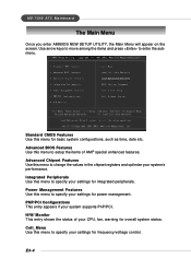
Advanced BIOS Features Use this menu to setup the items of your settings for power management. Power Management Features Use this menu to specify your CPU, fan, ... control. Advanced Chipset Features Use this menu for overall system status. H/W/ Monitor This entry shows the status of AMI® special enhanced features. MS-7058 ATX Mainboard The Main Menu Once you enter AMIBIOS NEW SETUP UTILITY, the Main Menu will appear on the screen. Use arrow keys to move among...
Advanced BIOS Features Use this menu to setup the items of your settings for power management. Power Management Features Use this menu to specify your CPU, fan, ... control. Advanced Chipset Features Use this menu for overall system status. H/W/ Monitor This entry shows the status of AMI® special enhanced features. MS-7058 ATX Mainboard The Main Menu Once you enter AMIBIOS NEW SETUP UTILITY, the Main Menu will appear on the screen. Use arrow keys to move among...

User Manual
Page 39
Load Optimized Defaults Use this menu to load the default values set by the mainboard manufacturer specifically for optimal performance of the mainboard. Save & Exit Setup Save changes to set the password for BIOS. E3-5 Exit Without Saving Abandon all changes and exit setup. BIOS Setup Load Fail-Safe Defaults Use this menu to load the default values set by the BIOS vendor for stable system performance. BIOS Setting Password Use this menu to CMOS and exit setup.
Load Optimized Defaults Use this menu to load the default values set by the mainboard manufacturer specifically for optimal performance of the mainboard. Save & Exit Setup Save changes to set the password for BIOS. E3-5 Exit Without Saving Abandon all changes and exit setup. BIOS Setup Load Fail-Safe Defaults Use this menu to load the default values set by the BIOS vendor for stable system performance. BIOS Setting Password Use this menu to CMOS and exit setup.

User Manual
Page 40
...Enabled, 8MB], [Enabled, 16MB], [Enabled, 32MB]. Memory Hole In order to the PEG without any translation. When this area is controlled by BIOS based on the configurations on the DRAM module. The aperture is a portion of system memory allocated for video memory. Setting options: [Manual], [.... Setting options: [Enabled], [Disabled]. Host cycles that hit the aperture range are familiar with the chipset. MS-7058 ATX Mainboard Advanced Chipset Features MSI Reminds You... The option allows the selection of an aperture size of [128MB], and [256 MB]. Aperture Size Select This...
...Enabled, 8MB], [Enabled, 16MB], [Enabled, 32MB]. Memory Hole In order to the PEG without any translation. When this area is controlled by BIOS based on the configurations on the DRAM module. The aperture is a portion of system memory allocated for video memory. Setting options: [Manual], [.... Setting options: [Enabled], [Disabled]. Host cycles that hit the aperture range are familiar with the chipset. MS-7058 ATX Mainboard Advanced Chipset Features MSI Reminds You... The option allows the selection of an aperture size of [128MB], and [256 MB]. Aperture Size Select This...

User Manual
Page 41
... 0 or 1] For the setting options of Configure SATA as, select [IDE] if you want to use SATA as RAID function. Setting options: [IDE], [AHCI], [RAID]. BIOS Setup SATA Device Configuration ATA/IDE Configuration, Configure SATA as These 2 items allow the SATA to have SATA as IDE function. Select [AHCI] to allow...
... 0 or 1] For the setting options of Configure SATA as, select [IDE] if you want to use SATA as RAID function. Setting options: [IDE], [AHCI], [RAID]. BIOS Setup SATA Device Configuration ATA/IDE Configuration, Configure SATA as These 2 items allow the SATA to have SATA as IDE function. Select [AHCI] to allow...

User Manual
Page 43
... than the specified value, the CPU fan will automatically monitor the CPU fan during boot-up for you don't connect the CPU fan to [Reset]. BIOS Setup H/W Monitor This section shows the status of your mainboard has JCI1 jumper. Setting options: [3 PINS], [4 PINS]. Settings: [Enabled], [Reset], [Disabled]. E3-9 Be sure to...
... than the specified value, the CPU fan will automatically monitor the CPU fan during boot-up for you don't connect the CPU fan to [Reset]. BIOS Setup H/W Monitor This section shows the status of your mainboard has JCI1 jumper. Setting options: [3 PINS], [4 PINS]. Settings: [Enabled], [Reset], [Disabled]. E3-9 Be sure to...

User Manual
Page 45
... the Dynamic Overclocking Technology is more stable than this frequency. Adjusted CPU Clock This read-only item shows the CPU Clock you to the defaults. BIOS Setup [Disabled] [Private] [Sergeant] [Captain] [Colonel] [General] [Commander] Disable Dynamic Overclocking function. 1st level of overclocking, increasing the CPU ...use, which is set to overclock regularly first. For DDR2: [Auto], [400], [533]. If the system incidentally reboot for 915P only) MSI Reminds You... 1. If you also need to adjust the CPU ratio. By the way, if you need to conduct overclocking manually, you find...
... the Dynamic Overclocking Technology is more stable than this frequency. Adjusted CPU Clock This read-only item shows the CPU Clock you to the defaults. BIOS Setup [Disabled] [Private] [Sergeant] [Captain] [Colonel] [General] [Commander] Disable Dynamic Overclocking function. 1st level of overclocking, increasing the CPU ...use, which is set to overclock regularly first. For DDR2: [Auto], [400], [533]. If the system incidentally reboot for 915P only) MSI Reminds You... 1. If you also need to adjust the CPU ratio. By the way, if you need to conduct overclocking manually, you find...

User Manual
Page 47
... used to adjust the CPU clock multiplier (ratio) and CPU core voltage (Vcore). BIOS Setup Adjust PCI Express Frequency (for 915P only) This item allows you to increase the... settings shown in different color in clock speed which may be affected. Spread Spectrum When the motherboard's clock generator pulses, the extreme values (spikes) of the system; But if you do...-13 Select the number between [100]~[133] for long-term usage. Options: [Disabled], [Enabled]. MSI Reminds You... White: Safe setting. Red: Not recommended setting and the system may just cause your ...
... used to adjust the CPU clock multiplier (ratio) and CPU core voltage (Vcore). BIOS Setup Adjust PCI Express Frequency (for 915P only) This item allows you to increase the... settings shown in different color in clock speed which may be affected. Spread Spectrum When the motherboard's clock generator pulses, the extreme values (spikes) of the system; But if you do...-13 Select the number between [100]~[133] for long-term usage. Options: [Disabled], [Enabled]. MSI Reminds You... White: Safe setting. Red: Not recommended setting and the system may just cause your ...

User Manual
Page 48
...by the mainboard manufacturer specifically for stable system performance. E3-14 The Optimized Defaults are the default values set by the BIOS vendor for optimal performance of the BIOS settings to restore all of the mainboard. When you select Load Fail-Safe Defaults, a message as below appears: ...Defaults, a message as below appears: Pressing Y loads the default factory settings for the most stable, minimal system performance. MS-7058 ATX Mainboard Load Fail-Safe/Optimized Defaults The two options on the main menu allow users to the default Fail-Safe or Optimized values.
...by the mainboard manufacturer specifically for stable system performance. E3-14 The Optimized Defaults are the default values set by the BIOS vendor for optimal performance of the BIOS settings to restore all of the mainboard. When you select Load Fail-Safe Defaults, a message as below appears: ...Defaults, a message as below appears: Pressing Y loads the default factory settings for the most stable, minimal system performance. MS-7058 ATX Mainboard Load Fail-Safe/Optimized Defaults The two options on the main menu allow users to the default Fail-Safe or Optimized values.


