User Manual
Page 8
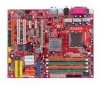
Getting Started Chapter 1. E1-3 The 915P/G Combo mainboard is based on Intel® 915P/G and Intel® ICH6/ICH6R chipset for choosing the 915P/G Combo (MS-7058) v1.X ATX mainboard. Designed to fit the advanced Intel® Pentium Prescott LGA775 processor, the 915P/G Combo mainboard delivers a high performance and professional desktop platform solution. Getting Started Getting Started Thank you for optimal system efficiency.
Getting Started Chapter 1. E1-3 The 915P/G Combo mainboard is based on Intel® 915P/G and Intel® ICH6/ICH6R chipset for choosing the 915P/G Combo (MS-7058) v1.X ATX mainboard. Designed to fit the advanced Intel® Pentium Prescott LGA775 processor, the 915P/G Combo mainboard delivers a high performance and professional desktop platform solution. Getting Started Getting Started Thank you for optimal system efficiency.
User Manual
Page 9
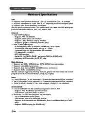
...DDR1 & DDR2 memory architecture. h Supports DDR2 533/400MHz and up to four Serial ATA devices. - Supports SATA hot plug (for 915G only). Hi-Speed USB (USB2.0) controller, 480Mb/sec, up to Two Ultra ATA drives. Supports PCI Express x16 interface. - PCI...Threading Technology. (For the latest information about CPU, please visit http://www.msi.com.tw/program/ products/mainboard/mbd/pro_mbd_cpu_support.php) Chipset h Intel® 915P/G chipset - Supports FSB 533/800MHz. - 7058 ATX Mainboard Mainboard Specifications CPU h Supports Intel® Pentium 4 Prescott LGA775 processors in ...
...DDR1 & DDR2 memory architecture. h Supports DDR2 533/400MHz and up to four Serial ATA devices. - Supports SATA hot plug (for 915G only). Hi-Speed USB (USB2.0) controller, 480Mb/sec, up to Two Ultra ATA drives. Supports PCI Express x16 interface. - PCI...Threading Technology. (For the latest information about CPU, please visit http://www.msi.com.tw/program/ products/mainboard/mbd/pro_mbd_cpu_support.php) Chipset h Intel® 915P/G chipset - Supports FSB 533/800MHz. - 7058 ATX Mainboard Mainboard Specifications CPU h Supports Intel® Pentium 4 Prescott LGA775 processors in ...
User Manual
Page 10
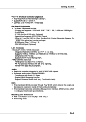
...ATX Form Factor: 24.4 cm (W) x 30.5 cm (L) h 9 mounting holes E1-5 Integrated Fast Ethernet MAC and PHY in Intel® ICH6/ICH6R chipset. Compliance with 360K, 720K, 1.2M, 1.44M and 2.88Mbytes - 1 serial port - 1 VGA port (for 8100S only). - h 8-channel audio codec CMedia CMI9880L. - h The mainboard...which records your mainboard specifications. Compliance with 2.5 GHz signaling. - 10/100/1000 IEEE 802.3 compliant. h Connect up to 4 Ultra ATA 133 devices. X1 PCI Express interface with Azalia 1.X Spec. - Supports 10Mb/s, 100Mb/s and 1000Mb/s (1000Mb/s for 915G only, Optional)...
...ATX Form Factor: 24.4 cm (W) x 30.5 cm (L) h 9 mounting holes E1-5 Integrated Fast Ethernet MAC and PHY in Intel® ICH6/ICH6R chipset. Compliance with 360K, 720K, 1.2M, 1.44M and 2.88Mbytes - 1 serial port - 1 VGA port (for 8100S only). - h 8-channel audio codec CMedia CMI9880L. - h The mainboard...which records your mainboard specifications. Compliance with 2.5 GHz signaling. - 10/100/1000 IEEE 802.3 compliant. h Connect up to 4 Ultra ATA 133 devices. X1 PCI Express interface with Azalia 1.X Spec. - Supports 10Mb/s, 100Mb/s and 1000Mb/s (1000Mb/s for 915G only, Optional)...

User Manual
Page 11
... 915P/G B AT T + SATA2 SATA4 SATA1 SATA3 IDE1 J B AT 1 JUSB1 ICH6/ ICH6R S YS FAN 1 VIA VT6410 IDE 2 IDE 3 JUSB2 JDB1 JFP2 JFP1 ATX1 915P/G Combo (MS-7058) v1.X ATX Mainboard E1-6 7058 ATX Mainboard Mainboard Layout W in bo nd W 83 627 TH F Top : mouse Bottom: keyboard Top : Parallel Port Bottom: COM A VGA port (Optional) C P U FA N 1 J C 11 J IR...
... 915P/G B AT T + SATA2 SATA4 SATA1 SATA3 IDE1 J B AT 1 JUSB1 ICH6/ ICH6R S YS FAN 1 VIA VT6410 IDE 2 IDE 3 JUSB2 JDB1 JFP2 JFP1 ATX1 915P/G Combo (MS-7058) v1.X ATX Mainboard E1-6 7058 ATX Mainboard Mainboard Layout W in bo nd W 83 627 TH F Top : mouse Bottom: keyboard Top : Parallel Port Bottom: COM A VGA port (Optional) C P U FA N 1 J C 11 J IR...

User Manual
Page 12
Hardware Setup Hardware Setup This chapter tells you how to install the CPU, memory modules, and expansion cards, as well as the mouse, keyboard, etc. Also, it provides the instructions on connecting the peripheral devices, such as how to setup the jumpers on the mainboard. While doing the installation, be careful in holding the components and follow the installation procedures. E2-1 Hardware Setup Chapter 2.
Hardware Setup Hardware Setup This chapter tells you how to install the CPU, memory modules, and expansion cards, as well as the mouse, keyboard, etc. Also, it provides the instructions on connecting the peripheral devices, such as how to setup the jumpers on the mainboard. While doing the installation, be careful in holding the components and follow the installation procedures. E2-1 Hardware Setup Chapter 2.

User Manual
Page 14
... about CPU, please visit http://www.msi.com.tw/ program/products/mainboard/mbd/pro_mbd_cpu_support.php. We do not have the CPU cooler, contact your components are able to prevent overheating. Introduction to support overclocking. Overclocking This motherboard is the Pin 1 indicator E2-3 ...If you are installing the CPU, make sure your dealer to ensure the safety of CPU. However, please make sure to install the cooler to tolerate such abnormal setting, while doing overclocking. Replacing the CPU While replacing the CPU, always turn off the ATX...
... about CPU, please visit http://www.msi.com.tw/ program/products/mainboard/mbd/pro_mbd_cpu_support.php. We do not have the CPU cooler, contact your components are able to prevent overheating. Introduction to support overclocking. Overclocking This motherboard is the Pin 1 indicator E2-3 ...If you are installing the CPU, make sure your dealer to ensure the safety of CPU. However, please make sure to install the cooler to tolerate such abnormal setting, while doing overclocking. Replacing the CPU While replacing the CPU, always turn off the ATX...

User Manual
Page 15
... you install the CPU, always cover it to prevent overheating. Remove the cap from damage. Meanwhile, do not have the cooler, contact your CPU & mainboard. 1. Wrong installation will cause the damage of socket reveal. 4. The pins of your dealer to install the CPU & cooler correctly. MS-7058... ATX Mainboard CPU & Cooler Installation When you do not forget to apply some silicon heat transfer compound on the top to protect the contact from ...
... you install the CPU, always cover it to prevent overheating. Remove the cap from damage. Meanwhile, do not have the cooler, contact your CPU & mainboard. 1. Wrong installation will cause the damage of socket reveal. 4. The pins of your dealer to install the CPU & cooler correctly. MS-7058... ATX Mainboard CPU & Cooler Installation When you do not forget to apply some silicon heat transfer compound on the top to protect the contact from ...

User Manual
Page 17
Press the four hooks down to avoid damaging. 3. locking switch MSI Reminds You... 1. Do not touch the CPU socket pins to fasten the... until its four clips get wedged into the holes of the CPU is firmly installed before turning on the mainboard with the hook under retention tab. 10. Align the holes on your CPU cooler is 20 cycles. Please... note that the clip-ends are correctly inserted. Turn over the mainboard to confirm that the mating/unmating durability of the mainboard. 11. MS-7058 ATX Mainboard 9. Therefore we suggest you do not plug/unplug the CPU too often.
Press the four hooks down to avoid damaging. 3. locking switch MSI Reminds You... 1. Do not touch the CPU socket pins to fasten the... until its four clips get wedged into the holes of the CPU is firmly installed before turning on the mainboard with the hook under retention tab. 10. Align the holes on your CPU cooler is 20 cycles. Please... note that the clip-ends are correctly inserted. Turn over the mainboard to confirm that the mating/unmating durability of the mainboard. 11. MS-7058 ATX Mainboard 9. Therefore we suggest you do not plug/unplug the CPU too often.
User Manual
Page 18
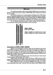
...rate by transferring data twice per cycle. Wrong installation may cause damage of memory module, and its speed is not backwardly compatible and only motherboards specifically designed for DDR1, and requires 28% less power than 1.3" in DDR1 slot (DIMM2 & DIMM4). E2-7 DDR1 SDRAM is similar... to DDR2 & DDR1 SDRAM DDR2 is a new technology of mainboard. For the updated supporting memory modules, please visit http://www.msi. Since DDR2 modules are for DDR1 memory module Introduction to conventional SDRAM, but they will be able to boot...
...rate by transferring data twice per cycle. Wrong installation may cause damage of memory module, and its speed is not backwardly compatible and only motherboards specifically designed for DDR1, and requires 28% less power than 1.3" in DDR1 slot (DIMM2 & DIMM4). E2-7 DDR1 SDRAM is similar... to DDR2 & DDR1 SDRAM DDR2 is a new technology of mainboard. For the updated supporting memory modules, please visit http://www.msi. Since DDR2 modules are for DDR1 memory module Introduction to conventional SDRAM, but they will be able to boot...
User Manual
Page 19
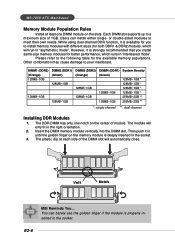
Each DIMM slot supports up to your mainboard. However, it is available for you install same-size memory modules for better performance, which will run in the socket. DIMM1 (DDR2) (Orange) 128MB~1GB ... is strongly recommended that you to meet their own needs. The DDR DIMM has only one DIMM module on the center of module. Volt Notch MSI Reminds You... or double-sided modules to install memory modules with different sizes (for the available memory populations. E2-8 Insert the DIMM memory module vertically...
Each DIMM slot supports up to your mainboard. However, it is available for you install same-size memory modules for better performance, which will run in the socket. DIMM1 (DDR2) (Orange) 128MB~1GB ... is strongly recommended that you to meet their own needs. The DDR DIMM has only one DIMM module on the center of module. Volt Notch MSI Reminds You... or double-sided modules to install memory modules with different sizes (for the available memory populations. E2-8 Insert the DIMM memory module vertically...

User Manual
Page 20
..., 12, 23 & 24 to the CPU. Power supply of the mainboard. 2. There is used to provide power to avoid wrong installation. JPW1 42 31 JPW1 Pin Definition PIN SIGNAL 1 GND 2 GND 3 12V 4 12V MSI Reminds You... 1. ATX 12V power connection should be caused. Then push down the power supply... at the right hand). You may use the 20-pin ATX power supply, please plug your power supply along with pin 1 & pin 13 (refer to connect an ATX 24-pin power supply. Hardware Setup Power Supply The mainboard supports ATX power supply for system stability. 3. If you like to ...
..., 12, 23 & 24 to the CPU. Power supply of the mainboard. 2. There is used to provide power to avoid wrong installation. JPW1 42 31 JPW1 Pin Definition PIN SIGNAL 1 GND 2 GND 3 12V 4 12V MSI Reminds You... 1. ATX 12V power connection should be caused. Then push down the power supply... at the right hand). You may use the 20-pin ATX power supply, please plug your power supply along with pin 1 & pin 13 (refer to connect an ATX 24-pin power supply. Hardware Setup Power Supply The mainboard supports ATX power supply for system stability. 3. If you like to ...

User Manual
Page 21
MS-7058 ATX Mainboard Back Panel The back panel provides the following connectors: Mouse Parallel S/PDIF LAN L-In RS-Out Keyboard COM A VGA port (Optional) USB Ports L-Out CS-Out Mic SPDIF Out Mouse/Keyboard Connector The mainboard provides a standard PS/2® mouse/keyboard mini.../Keyboard data 2 NC No connection 3 GND Ground 4 VCC +5V 5 Mouse/KeyboardClock Mouse/Keyboardclock 6 NC No connection VGA Connector (Optional) The mainboard provides a DB 15-pin female connector to connect a VGA monitor. 5 1 15 11 VGA Connector (DB 15-pin) Pin Signal Description Pin ...
MS-7058 ATX Mainboard Back Panel The back panel provides the following connectors: Mouse Parallel S/PDIF LAN L-In RS-Out Keyboard COM A VGA port (Optional) USB Ports L-Out CS-Out Mic SPDIF Out Mouse/Keyboard Connector The mainboard provides a standard PS/2® mouse/keyboard mini.../Keyboard data 2 NC No connection 3 GND Ground 4 VCC +5V 5 Mouse/KeyboardClock Mouse/Keyboardclock 6 NC No connection VGA Connector (Optional) The mainboard provides a DB 15-pin female connector to connect a VGA monitor. 5 1 15 11 VGA Connector (DB 15-pin) Pin Signal Description Pin ...

User Manual
Page 22
... high speed communication port that sends/receives 16 bytes FIFOs. You can attach a serial mouse or other USBcompatible devices. Hardware Setup Serial Port Connector The mainboard offers one 9-pin male DIN connector as keyboard, mouse or other serial devices directly to the connector. 1 2 3 4 5 PIN 1 2 3 4 6 7 8 9 5 9-Pin ...or Transmit Data Data Terminal Ready) Ground Data Set Ready Request To Send Clear To Send Ring Indicate USB Connectors The mainboard provides an OHCI (Open Host Controller Interface) Universal Serial Bus root for attaching USB devices such as the serial port....
... high speed communication port that sends/receives 16 bytes FIFOs. You can attach a serial mouse or other USBcompatible devices. Hardware Setup Serial Port Connector The mainboard offers one 9-pin male DIN connector as keyboard, mouse or other serial devices directly to the connector. 1 2 3 4 5 PIN 1 2 3 4 6 7 8 9 5 9-Pin ...or Transmit Data Data Terminal Ready) Ground Data Set Ready Request To Send Clear To Send Ring Indicate USB Connectors The mainboard provides an OHCI (Open Host Controller Interface) Universal Serial Bus root for attaching USB devices such as the serial port....

User Manual
Page 23
... operation and can connect a network cable to be transferred at 1000, 100 or 10Mbps. However, there is a connector for microphones. MS-7058 ATX Mainboard LAN (RJ-45) Jack The mainboard provides 1 standard RJ-45 jack for connection to 4-/5.1-channel audio. RJ-45 LAN Jack Giga-bit LAN Pin Definition PIN SIGNAL 1 D0P 2 D0N...
... operation and can connect a network cable to be transferred at 1000, 100 or 10Mbps. However, there is a connector for microphones. MS-7058 ATX Mainboard LAN (RJ-45) Jack The mainboard provides 1 standard RJ-45 jack for connection to 4-/5.1-channel audio. RJ-45 LAN Jack Giga-bit LAN Pin Definition PIN SIGNAL 1 D0P 2 D0N...

User Manual
Page 24
Hardware Setup Parallel Port Connector: LPT1 The mainboard provides a 25-pin female centronic connector as LPT. A parallel port is a standard printer port that supports Enhanced Parallel Port (EPP) and Extended Capabilities Parallel Port (...
Hardware Setup Parallel Port Connector: LPT1 The mainboard provides a 25-pin female centronic connector as LPT. A parallel port is a standard printer port that supports Enhanced Parallel Port (EPP) and Extended Capabilities Parallel Port (...
User Manual
Page 25
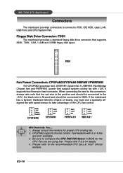
... CPU cooling fan. 2. GND +12V Sensor Control CPUFAN2 GND +12V NC SYSFAN1 GND +12V NC PWRFAN1 GND +12V Sensor NBFAN1 MSI Reminds You... 1. E2-14 If the mainboard has a System Hardware Monitor chipset on-board, you are both available. 3. Be sure to take note that supports 360K, 720K,... 1.2M, 1.44M and 2.88M floppy disk types. MS-7058 ATX Mainboard Connectors The mainboard provides connectors to connect to FDD, IDE HDD, case, LAN, USB Ports and CPU/System FAN. FDD1 Fan Power Connectors: CPUFAN2/SYSFAN1/...
... CPU cooling fan. 2. GND +12V Sensor Control CPUFAN2 GND +12V NC SYSFAN1 GND +12V NC PWRFAN1 GND +12V Sensor NBFAN1 MSI Reminds You... 1. E2-14 If the mainboard has a System Hardware Monitor chipset on-board, you are both available. 3. Be sure to take note that supports 360K, 720K,... 1.2M, 1.44M and 2.88M floppy disk types. MS-7058 ATX Mainboard Connectors The mainboard provides connectors to connect to FDD, IDE HDD, case, LAN, USB Ports and CPU/System FAN. FDD1 Fan Power Connectors: CPUFAN2/SYSFAN1/...

User Manual
Page 26
... always be connected to the hard disk documentation supplied by hard disk vendors for jumper setting instructions. MSI Reminds You... Hardware Setup Hard Disk Connectors: IDE1, IDE2 & IDE3 (IDE 2 & IDE3 are optional) The mainboard has one 32-bit Ultra DMA 66/100 IDE controller integrated in the optional VIA 6410 IDE Raid...
... always be connected to the hard disk documentation supplied by hard disk vendors for jumper setting instructions. MSI Reminds You... Hardware Setup Hard Disk Connectors: IDE1, IDE2 & IDE3 (IDE 2 & IDE3 are optional) The mainboard has one 32-bit Ultra DMA 66/100 IDE controller integrated in the optional VIA 6410 IDE Raid...
User Manual
Page 27
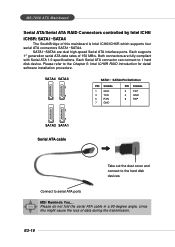
... Introduction for detail software installation procedure. Please refer to serial ATA ports MSI Reminds You... E2-16 Each Serial ATA connector can connect to 1 hard disk device. Both connectors are dual high-speed Serial ATA interface ports. MS-7058 ATX Mainboard Serial ATA/Serial ATA RAID Connectors controlled by Intel ICH6/ ICH6R: SATA1... of this might cause the loss of data during the transmission. Please do not fold the serial ATA cable in a 90-degree angle, since this mainboard is Intel ICH6/ICH6R which supports four serial ATA connectors SATA1~SATA4.
... Introduction for detail software installation procedure. Please refer to serial ATA ports MSI Reminds You... E2-16 Each Serial ATA connector can connect to 1 hard disk device. Both connectors are dual high-speed Serial ATA interface ports. MS-7058 ATX Mainboard Serial ATA/Serial ATA RAID Connectors controlled by Intel ICH6/ ICH6R: SATA1... of this might cause the loss of data during the transmission. Please do not fold the serial ATA cable in a 90-degree angle, since this mainboard is Intel ICH6/ICH6R which supports four serial ATA connectors SATA1~SATA4.

User Manual
Page 28
JFP2 Pin Definition PIN SIGNAL 1 GND 3 SLED 5 PLED 7 NC PIN SIGNAL 2 SPK- 4 BUZ+ 6 BUZ- 8 SPK+ E2-17 Hardware Setup Front Panel Connectors: JFP1 & JFP2 The mainboard provides two front panel connectors for electrical connection to GND Reserved. Do not use. JFP1 is compliant with Intel® Front Panel I/O Connectivity Design Guide. ...
JFP2 Pin Definition PIN SIGNAL 1 GND 3 SLED 5 PLED 7 NC PIN SIGNAL 2 SPK- 4 BUZ+ 6 BUZ- 8 SPK+ E2-17 Hardware Setup Front Panel Connectors: JFP1 & JFP2 The mainboard provides two front panel connectors for electrical connection to GND Reserved. Do not use. JFP1 is compliant with Intel® Front Panel I/O Connectivity Design Guide. ...

User Manual
Page 29
... channel 10 SENSE2_RETIRN Jack detection return from the High Definition Audio CODEC jack detection resistor network 8 KEY Connector Key 9 PORT 2L Analog Port 2 - MS-7058 ATX Mainboard CD-In Connector: JCD1 The connector is connected to the front panel audio and is connected. 5 PORT 2R Analog Port 2 - signals BIOS that a High Definition...
... channel 10 SENSE2_RETIRN Jack detection return from the High Definition Audio CODEC jack detection resistor network 8 KEY Connector Key 9 PORT 2L Analog Port 2 - MS-7058 ATX Mainboard CD-In Connector: JCD1 The connector is connected to the front panel audio and is connected. 5 PORT 2R Analog Port 2 - signals BIOS that a High Definition...


