User Guide
Page 2
... trademarks of Phoenix Technologies Ltd. W indows® NT/XP/Vista are registered trademarks of International Business Machines Corporation. Revision History Revision V1.0 Revision History First Release Date January 2009 Technical Support If a problem arises with your place of purchase or local distributor. Alternatively, please try the following help resources for FAQ, technical guide, BIOS updates, driver updates, and other...
... trademarks of Phoenix Technologies Ltd. W indows® NT/XP/Vista are registered trademarks of International Business Machines Corporation. Revision History Revision V1.0 Revision History First Release Date January 2009 Technical Support If a problem arises with your place of purchase or local distributor. Alternatively, please try the following help resources for FAQ, technical guide, BIOS updates, driver updates, and other...
User Guide
Page 8
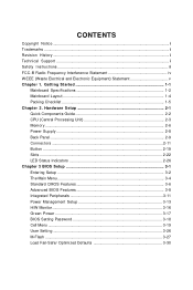
... 2-3 Memory ...2-6 Power Supply ...2-8 Back Panel ...2-9 Connectors ...2-11 Button ...2-19 Slots ...2-22 LED Status Indicators 2-26 Chapter 3 BIOS Setup 3-1 Entering Setup ...3-2 The Main Menu ...3-4 Standard CMOS Features 3-6 Advanced BIOS Features 3-8 Integrated Peripherals 3-11 Power Management Setup 3-13 H/W Monitor ...3-16 Green Power ...3-17 BIOS Setting Password 3-18 Cell Menu ...3-19 User Setting ...3-26 M-Flash ...3-27 Load Fail-Safe/ Optimized Defaults 3-30 CONTENTS Copyright Notice ...ii Trademarks ...ii Revision History ...ii Technical Support ...ii Safety Instructions...
... 2-3 Memory ...2-6 Power Supply ...2-8 Back Panel ...2-9 Connectors ...2-11 Button ...2-19 Slots ...2-22 LED Status Indicators 2-26 Chapter 3 BIOS Setup 3-1 Entering Setup ...3-2 The Main Menu ...3-4 Standard CMOS Features 3-6 Advanced BIOS Features 3-8 Integrated Peripherals 3-11 Power Management Setup 3-13 H/W Monitor ...3-16 Green Power ...3-17 BIOS Setting Password 3-18 Cell Menu ...3-19 User Setting ...3-26 M-Flash ...3-27 Load Fail-Safe/ Optimized Defaults 3-30 CONTENTS Copyright Notice ...ii Trademarks ...ii Revision History ...ii Technical Support ...ii Safety Instructions...
User Guide
Page 11
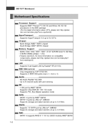
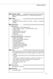
... 3.0 Gb/s ESATA - Supports storage and data transfers at up to 8-channel audio with jack sensing IDE - 1 IDE port by JMicron® JMB322 - Supports Ultra DMA 66/ 100/ 133 mode - msi.com.tw/index.php?func=cpuform2) HyperTransport - Supports Dual Gigabit LAN by JMicron® JMB362 - Supports 2 IEEE1394 ports (rear x 1, front x 1) Audio - Supports 1 E-SATA port by Realtek® RTL8111DL IEEE 1394 (optional) - SATA1~6 supports RAID 0/ 1/ 10/ 5 or JBOD mode by AMD® SB750 1-2 MS-7577 Mainboard Motherboard Specifications Processor Support -
... 3.0 Gb/s ESATA - Supports storage and data transfers at up to 8-channel audio with jack sensing IDE - 1 IDE port by JMicron® JMB322 - Supports Ultra DMA 66/ 100/ 133 mode - msi.com.tw/index.php?func=cpuform2) HyperTransport - Supports Dual Gigabit LAN by JMicron® JMB362 - Supports 2 IEEE1394 ports (rear x 1, front x 1) Audio - Supports 1 E-SATA port by Realtek® RTL8111DL IEEE 1394 (optional) - SATA1~6 supports RAID 0/ 1/ 10/ 5 or JBOD mode by AMD® SB750 1-2 MS-7577 Mainboard Motherboard Specifications Processor Support -
User Guide
Page 12
... Back panel - 1 PS/2 mouse/ 1 PS/2 keyboard port - 1 Coaxial S/PDIF-out jack / 1 Optical S/PDIF-out port - 7 USB 2.0 Ports - 1 E-SATA/USB common port - 1 IEEE 1394 port (optional) - 2 LAN jacks - 6 flexible audio jacks On-Board Pinheaders/ Connectors - 2 USB 2.0 pinheaders - 1 IEEE 1394 pinheader (optional) - 1 COM port pinheader - 1 CD-in pinheader - 1 TPM Module pinheader - 1 Chassis Intrusion pinheader - 1 Front Panel Audio pinheader - 1 S/PDIF-out pinheader - 1 Debug LED Slots - 4 PCI Express gen2 x16 slots, support CrossFireXTM technology a. the PCIE x16 slots (PCI_E3 & PCI_E5) support up...
... Back panel - 1 PS/2 mouse/ 1 PS/2 keyboard port - 1 Coaxial S/PDIF-out jack / 1 Optical S/PDIF-out port - 7 USB 2.0 Ports - 1 E-SATA/USB common port - 1 IEEE 1394 port (optional) - 2 LAN jacks - 6 flexible audio jacks On-Board Pinheaders/ Connectors - 2 USB 2.0 pinheaders - 1 IEEE 1394 pinheader (optional) - 1 COM port pinheader - 1 CD-in pinheader - 1 TPM Module pinheader - 1 Chassis Intrusion pinheader - 1 Front Panel Audio pinheader - 1 S/PDIF-out pinheader - 1 Debug LED Slots - 4 PCI Express gen2 x16 slots, support CrossFireXTM technology a. the PCIE x16 slots (PCI_E3 & PCI_E5) support up...
User Guide
Page 22
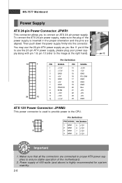
... used to provide power to the CPU. 5 1 8 4 Pin Definition PIN SIGNAL PIN SIGNAL 1 GND 2 GND 3 GND 4 GND 5 +12V 6 +12V 7 +12V 8 +12V pin 13 pin 12 Important 1. MS-7577 Mainboard Power Supply ATX 24-pin Power Connector: JPWR1 This connector allows you like to use the 20-pin ATX power supply as you to connect an ATX 24-pin power supply. Maker sure that all the connectors are aligned. You may use the 20-pin ATX power supply, please plug your power supply along with pin 1 & pin 13...
... used to provide power to the CPU. 5 1 8 4 Pin Definition PIN SIGNAL PIN SIGNAL 1 GND 2 GND 3 GND 4 GND 5 +12V 6 +12V 7 +12V 8 +12V pin 13 pin 12 Important 1. MS-7577 Mainboard Power Supply ATX 24-pin Power Connector: JPWR1 This connector allows you like to use the 20-pin ATX power supply as you to connect an ATX 24-pin power supply. Maker sure that all the connectors are aligned. You may use the 20-pin ATX power supply, please plug your power supply along with pin 1 & pin 13...
User Guide
Page 25
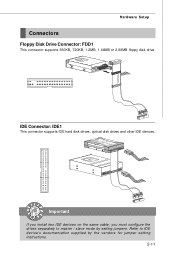
Refer to master / slave mode by the vendors for jumper setting instructions. 2-11 IDE Connector: IDE1 This connector supports IDE hard disk drives, optical disk drives and other IDE devices. Important If you install two IDE devices on the same cable, you must configure the drives separately to IDE device's documentation supplied by setting jumpers. Hardware Setup Connectors Floppy Disk Drive Connector: FDD1 This connector supports 360KB, 720KB, 1.2MB, 1.44MB or 2.88MB floppy disk drive.
Refer to master / slave mode by the vendors for jumper setting instructions. 2-11 IDE Connector: IDE1 This connector supports IDE hard disk drives, optical disk drives and other IDE devices. Important If you install two IDE devices on the same cable, you must configure the drives separately to IDE device's documentation supplied by setting jumpers. Hardware Setup Connectors Floppy Disk Drive Connector: FDD1 This connector supports 360KB, 720KB, 1.2MB, 1.44MB or 2.88MB floppy disk drive.
User Guide
Page 27
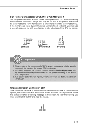
..., you must enter the BIOS utility and clear the record. CPUFAN1 supports fan control. The system will automatically control the CPU fan speed according to the chassis intrusion switch cable. Fan cooler set with +12V. You can install Overclocking Center utility that the red wire is Ground and should be connected to take advantage of the CPU fan control. GND CINTRU 2 1 2-13 If the motherboard has a System Hardware Monitor chipset on the screen. W hen connecting the wire to the connectors, always...
..., you must enter the BIOS utility and clear the record. CPUFAN1 supports fan control. The system will automatically control the CPU fan speed according to the chassis intrusion switch cable. Fan cooler set with +12V. You can install Overclocking Center utility that the red wire is Ground and should be connected to take advantage of the CPU fan control. GND CINTRU 2 1 2-13 If the motherboard has a System Hardware Monitor chipset on the screen. W hen connecting the wire to the connectors, always...
User Guide
Page 36
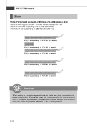
... jumpers, switches or BIOS configuration. 2-22 The PCIE x1 slot supports up to 250 MB/s transfer rate. PCI_E1 supports up to PCIE 2.0 x16 speed PCI_E2 supports up to PCIE 2.0 x1 speed PCI_E3 supports up to PCIE 2.0 x8 speed PCI_E4 supports up to PCIE 2.0 x16 speed PCI_E5 supports up to PCIE 2.0 x8 speed Important When adding or removing expansion cards, make sure that you unplug the power supply first. The PCIE x16 slots support up to configure any necessary hardware or software settings...
... jumpers, switches or BIOS configuration. 2-22 The PCIE x1 slot supports up to 250 MB/s transfer rate. PCI_E1 supports up to PCIE 2.0 x16 speed PCI_E2 supports up to PCIE 2.0 x1 speed PCI_E3 supports up to PCIE 2.0 x8 speed PCI_E4 supports up to PCIE 2.0 x16 speed PCI_E5 supports up to PCIE 2.0 x8 speed Important When adding or removing expansion cards, make sure that you unplug the power supply first. The PCIE x16 slots support up to configure any necessary hardware or software settings...
User Guide
Page 37
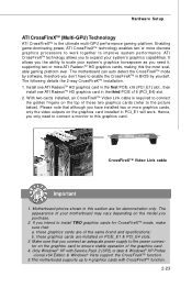
The motherboard can auto detect the CrossFireXTM mode by yourself. Please note that you connect an adequate power supply to the power connector on the graphics card to ensure stable operation of these graphics cards are installed on the top of the graphics card. 4. Motherboard photos shown in PCI_E1 will work together to the picture below). these two graphics cards (refer to improve sys tem performance. Hardware Setup ATI CrossFireXTM (Multi...
The motherboard can auto detect the CrossFireXTM mode by yourself. Please note that you connect an adequate power supply to the power connector on the graphics card to ensure stable operation of these graphics cards are installed on the top of the graphics card. 4. Motherboard photos shown in PCI_E1 will work together to the picture below). these two graphics cards (refer to improve sys tem performance. Hardware Setup ATI CrossFireXTM (Multi...
User Guide
Page 39
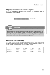
... I-R-Q, are typically connected to the PCI bus pins as jumpers, switches or BIOS configuration. The PCI IRQ pins are hardware lines over which devices can send interrupt signals to configure any necessary hardware or software settings for the expansion card to the microprocessor. Hardware Setup PCI (Peripheral Component Interconnect) Slot The PCI slot supports LAN card, SCSI card, USB card, and other add-on cards that comply with PCI specifications. 32-bit PCI Slot Important When adding or removing expansion cards, make sure that...
... I-R-Q, are typically connected to the PCI bus pins as jumpers, switches or BIOS configuration. The PCI IRQ pins are hardware lines over which devices can send interrupt signals to configure any necessary hardware or software settings for the expansion card to the microprocessor. Hardware Setup PCI (Peripheral Component Interconnect) Slot The PCI slot supports LAN card, SCSI card, USB card, and other add-on cards that comply with PCI specifications. 32-bit PCI Slot Important When adding or removing expansion cards, make sure that...
User Guide
Page 49
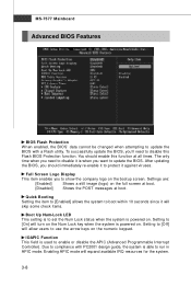
... to update the BIOS. Enabling APIC mode will allow users to use the arrow keys on the numeric keypad. MS-7577 Mainboard Advanced BIOS Features BIOS Flash Protection W hen enabled, the BIOS' data cannot be changed when attempting to update the BIOS with PC2001 design guide, the system is powered on. The only time when you should enable this Flash BIOS Protection function. Quick Booting Setting the item to [Enabled] allows the system to disable...
... to update the BIOS. Enabling APIC mode will allow users to use the arrow keys on the numeric keypad. MS-7577 Mainboard Advanced BIOS Features BIOS Flash Protection W hen enabled, the BIOS' data cannot be changed when attempting to update the BIOS with PC2001 design guide, the system is powered on. The only time when you should enable this Flash BIOS Protection function. Quick Booting Setting the item to [Enabled] allows the system to disable...
User Guide
Page 50
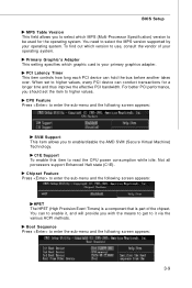
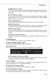
... Graphic's Adapter This setting specifies which MPS (Multi-Processor Specification) version to be used for a longer time and thus improve the effective PCI bandwidth. Chipset Feature Press to enter the sub-menu and the following screen appears: HPET The HPET (High Precision Event Timers) is a component that is your operating system. You need to select the MPS version supported by your primary graphics adapter. BIOS Setup MPS...
... Graphic's Adapter This setting specifies which MPS (Multi-Processor Specification) version to be used for a longer time and thus improve the effective PCI bandwidth. Chipset Feature Press to enter the sub-menu and the following screen appears: HPET The HPET (High Precision Event Timers) is a component that is your operating system. You need to select the MPS version supported by your primary graphics adapter. BIOS Setup MPS...
User Guide
Page 52
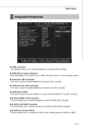
...1394 Controller This item allows you to enable/disable the onboard 2nd LAN controller. Onboard LAN Controller This item is used to decide whether to use a USB-interfaced device in the operating system. E-SATA/ HW RAID Controller This item allows you to enable/ disable the E-SATA & HW RAID controller. LAN Option ROM This item is used to enable/disable the onboard USB controller. E-SATA Controller Mode This item allows you to configure E-SATA mode. Setting options: [AHCI] or [IDE]. 3-11 USB Device Legacy Support Select [Enabled] if you need to invoke the Boot ROM of the LAN...
...1394 Controller This item allows you to enable/disable the onboard 2nd LAN controller. Onboard LAN Controller This item is used to decide whether to use a USB-interfaced device in the operating system. E-SATA/ HW RAID Controller This item allows you to enable/ disable the E-SATA & HW RAID controller. LAN Option ROM This item is used to enable/disable the onboard USB controller. E-SATA Controller Mode This item allows you to configure E-SATA mode. Setting options: [AHCI] or [IDE]. 3-11 USB Device Legacy Support Select [Enabled] if you need to invoke the Boot ROM of the LAN...
User Guide
Page 53
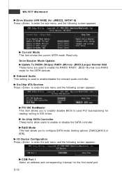
... (Large)/ Normal Hdd These items are used to enable the RAID0/ RAID1/ JBOD/ Normal (non-RAID) mode for reading/ writing to enter the sub-menu and the following screen appears. On-Chip ATA Devices Press to IDE drives. Setting options: [RAID],[AHCI] or [IDE]. On-Chip SATA Controller These items allow users to enable/disable the onboard audio controller. RAID Mode This item allows you to enable/ disable BIOS to configure SATA mode. I/O Device Configuration Press to enter the sub-menu and the following screen appears: COM Port 1 Select an...
... (Large)/ Normal Hdd These items are used to enable the RAID0/ RAID1/ JBOD/ Normal (non-RAID) mode for reading/ writing to enter the sub-menu and the following screen appears. On-Chip ATA Devices Press to IDE drives. Setting options: [RAID],[AHCI] or [IDE]. On-Chip SATA Controller These items allow users to enable/disable the onboard audio controller. RAID Mode This item allows you to enable/ disable BIOS to configure SATA mode. I/O Device Configuration Press to enter the sub-menu and the following screen appears: COM Port 1 Select an...
User Guide
Page 57
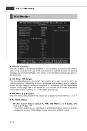
... opened. CPU Smart FAN Target The motherboard provides the Smart Fan function which can select a fan target value here. SYS FAN 1/ 2/ 3/ 4 Control This item allows users to keep it with in a specific range. To clear the warning message, set the field to speed up for the SYS FAN 1/ 2/ 3/ 4. MS-7577 Mainboard H/W Monitor Chassis Intrusion The field enables or disables the feature of the monitored hardware devices/ components such as CPU voltage, temperatures and all fans' speeds. 3-16...
... opened. CPU Smart FAN Target The motherboard provides the Smart Fan function which can select a fan target value here. SYS FAN 1/ 2/ 3/ 4 Control This item allows users to keep it with in a specific range. To clear the warning message, set the field to speed up for the SYS FAN 1/ 2/ 3/ 4. MS-7577 Mainboard H/W Monitor Chassis Intrusion The field enables or disables the feature of the monitored hardware devices/ components such as CPU voltage, temperatures and all fans' speeds. 3-16...
User Guide
Page 64
.... HT Link Control Press to access multiple banks simultaneously. It allows system to enter the sub-menu and the following screen appears. HT Incoming/ Outgoing Link Width These items allow you set the Hyper-Transport Link width. FSB/DRAM Ratio This item will remove (turn off) clocks from empty PCI slots to [DCT 0], [DCT 1] or [Both], some fields will automatically reduce the memory power supply.
.... HT Link Control Press to access multiple banks simultaneously. It allows system to enter the sub-menu and the following screen appears. HT Incoming/ Outgoing Link Width These items allow you set the Hyper-Transport Link width. FSB/DRAM Ratio This item will remove (turn off) clocks from empty PCI slots to [DCT 0], [DCT 1] or [Both], some fields will automatically reduce the memory power supply.
User Guide
Page 69
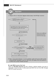
... Select BIOS file from the root directory of some graphics cards will cause dark screen during M-flash operation, and you may refer the beeps from " field Save changes and exit the BIOS setup SYSTEM Restart Please check USB drive/ Storage drive/ BIOS file status and reboot the system manually again. Start M-Flash 4 short beeps Check the storage device and file status Success Fail The selected file/ USB drive / Storage drive can 2 long beeps not be recognized. BIOS update successfully or Boot from the USB/ Storage (FAT...
... Select BIOS file from the root directory of some graphics cards will cause dark screen during M-flash operation, and you may refer the beeps from " field Save changes and exit the BIOS setup SYSTEM Restart Please check USB drive/ Storage drive/ BIOS file status and reboot the system manually again. Start M-Flash 4 short beeps Check the storage device and file status Success Fail The selected file/ USB drive / Storage drive can 2 long beeps not be recognized. BIOS update successfully or Boot from the USB/ Storage (FAT...

User Guide
Page 73
... The HD Audio Configuration software utility is under continuous update to 2-, 4-, 6-, 8- The setup screen will automatically appear. 2. a A-2 Click Realtek HD Audio Driver. channel or 7.1+2 channel audio operations. Hence, the program screens shown here in different operating systems. 1. MS-7577 Mainboard Installing the Realtek HD Audio Driver You need to install the driver for reference only. Follow the procedures described below to install the drivers for different operating systems. Installation for Windows XP/ Vista...
... The HD Audio Configuration software utility is under continuous update to 2-, 4-, 6-, 8- The setup screen will automatically appear. 2. a A-2 Click Realtek HD Audio Driver. channel or 7.1+2 channel audio operations. Hence, the program screens shown here in different operating systems. 1. MS-7577 Mainboard Installing the Realtek HD Audio Driver You need to install the driver for reference only. Follow the procedures described below to install the drivers for different operating systems. Installation for Windows XP/ Vista...
User Guide
Page 109
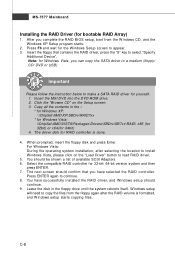
... driver disk for 32-bit/ 64-bit version system and then press ENTER. 7. Select the compatible RAID controller for RAID controller is formatted, and W indows setup starts copying files. Insert the MSI DVD into the DVD-ROM drive. 2. Press ENTER again to appear. 3. Copy all the contents in the floppy drive until the system reboots itself. Click the "Browse CD" on the "Load Driver" button to select "Specify Additional Device". After you have successfully installed the RAID driver, and...
... driver disk for 32-bit/ 64-bit version system and then press ENTER. 7. Select the compatible RAID controller for RAID controller is formatted, and W indows setup starts copying files. Insert the MSI DVD into the DVD-ROM drive. 2. Press ENTER again to appear. 3. Copy all the contents in the floppy drive until the system reboots itself. Click the "Browse CD" on the "Load Driver" button to select "Specify Additional Device". After you have successfully installed the RAID driver, and...
User Guide
Page 110
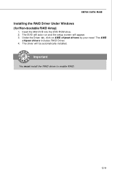
Insert the MSI DVD into the DVD-ROM drive. 2. Under the Driver tab, click on AMD chipset drivers by your need. The AMD chipset drivers includes RAID Driver. 4. Important You must install the RAID driver to enable RAID. The driver will appear. 3. C-9 SB750 SATA RAID Installing the RAID Driver Under Windows (for Non-bootable RAID Array) 1. The DVD will auto-run and the setup screen will be automatically installed.
Insert the MSI DVD into the DVD-ROM drive. 2. Under the Driver tab, click on AMD chipset drivers by your need. The AMD chipset drivers includes RAID Driver. 4. Important You must install the RAID driver to enable RAID. The driver will appear. 3. C-9 SB750 SATA RAID Installing the RAID Driver Under Windows (for Non-bootable RAID Array) 1. The DVD will auto-run and the setup screen will be automatically installed.


