
User Guide
Page 4
... Part 15 of the FCC Rules. iv power cord, if any, must accept any interference received, including interference that to radio communications. Micro-Star International MS-7577 This device complies with the emission limits. FCC-B Radio Frequency Interference Statement T h is eq uip men t h as been tested and found to comply with...
... Part 15 of the FCC Rules. iv power cord, if any, must accept any interference received, including interference that to radio communications. Micro-Star International MS-7577 This device complies with the emission limits. FCC-B Radio Frequency Interference Statement T h is eq uip men t h as been tested and found to comply with...
User Guide
Page 11
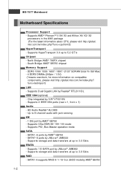
... Bridge: AMD® 790FX chipset - func=testreport) LAN - SATA7~8 ports by AMD® SB750 1-2 SATA1~6 supports RAID 0/ 1/ 10/ 5 or JBOD mode by JMicron® JMB322 - Supports PIO, Bus Master operation mode SATA - MS-7577 Mainboard Motherboard Specifications Processor Support - msi.com.tw/index.php... (total 16 GB Max) - 4 DDR3 DIMMs (240pin / 1.5V) (*means overclock, for more information on compatible components, please visit http://global.msi.com.tw/index.php? Supports 2 IEEE1394 ports (rear x 1, front x 1) Audio - Supports AMD® PhenomTM II X4/ X3 and Athlon X4...
... Bridge: AMD® 790FX chipset - func=testreport) LAN - SATA7~8 ports by AMD® SB750 1-2 SATA1~6 supports RAID 0/ 1/ 10/ 5 or JBOD mode by JMicron® JMB322 - Supports PIO, Bus Master operation mode SATA - MS-7577 Mainboard Motherboard Specifications Processor Support - msi.com.tw/index.php... (total 16 GB Max) - 4 DDR3 DIMMs (240pin / 1.5V) (*means overclock, for more information on compatible components, please visit http://global.msi.com.tw/index.php? Supports 2 IEEE1394 ports (rear x 1, front x 1) Audio - Supports AMD® PhenomTM II X4/ X3 and Athlon X4...
User Guide
Page 13
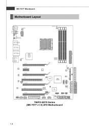
... SATA8 SATA3-4 S ATA1-2 SYSFAN2 FDD 1 JCI1 POS T_LED J COM1 I MM 4 Top: LAN Jack Bottom: USB ports AMD 790FX T:L i ne - O u t B:Mi c T:RS-Out M:CS-Out B:SS-Out SYSFAN4 PCI_E1 SY SFAN1 PCI_E2 LAN chip...chip J SP1 PCI_E4 Audio codec PCI2 PCI_E5 JAUD1 J CD1 (O ptional) J1394_1 Clock Gen. JP WR1 MS-7577 Mainboard Motherboard Layout Top : mouse Bottom: keyboard Top: Coaxial S/PDI F Buttom: Optical S/PDI F SY SFAN3 Top... JUSB1 JUS B2 OC DRIVE J TPM1 OC GEAR J FP1 JFP2 C L R_ C M OS 1 Gr een Power RESET1 POWER1 790FX-GD70 Series (MS-7577 v1.X) ATX Motherboard 1-4
... SATA8 SATA3-4 S ATA1-2 SYSFAN2 FDD 1 JCI1 POS T_LED J COM1 I MM 4 Top: LAN Jack Bottom: USB ports AMD 790FX T:L i ne - O u t B:Mi c T:RS-Out M:CS-Out B:SS-Out SYSFAN4 PCI_E1 SY SFAN1 PCI_E2 LAN chip...chip J SP1 PCI_E4 Audio codec PCI2 PCI_E5 JAUD1 J CD1 (O ptional) J1394_1 Clock Gen. JP WR1 MS-7577 Mainboard Motherboard Layout Top : mouse Bottom: keyboard Top: Coaxial S/PDI F Buttom: Optical S/PDI F SY SFAN3 Top... JUSB1 JUS B2 OC DRIVE J TPM1 OC GEAR J FP1 JFP2 C L R_ C M OS 1 Gr een Power RESET1 POWER1 790FX-GD70 Series (MS-7577 v1.X) ATX Motherboard 1-4
User Guide
Page 18
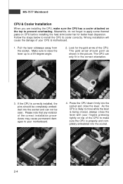
Meanwhile, do not forget to your motherboard. 4. T he gold arrow s hould point as shown in the correct orientation. 3. Please note... heat dispersion. The CPU can not be completely embedded into the socket and close the lever with your CPU & motherboard. 1. Press the CPU down firmly into the socket and can only fit in the picture. Make sure to raise...the lever up to make sure the CPU has a cooler attached on the top to install the CPU & cooler correctly. MS-7577 Mainboard CPU & Cooler Installation W hen you are installing the CPU, make sure the CPU is being closed, always...
Meanwhile, do not forget to your motherboard. 4. T he gold arrow s hould point as shown in the correct orientation. 3. Please note... heat dispersion. The CPU can not be completely embedded into the socket and close the lever with your CPU & motherboard. 1. Press the CPU down firmly into the socket and can only fit in the picture. Make sure to raise...the lever up to make sure the CPU has a cooler attached on the top to install the CPU & cooler correctly. MS-7577 Mainboard CPU & Cooler Installation W hen you are installing the CPU, make sure the CPU is being closed, always...

User Guide
Page 20
For more information on compatible components, please visit http://global.msi.com. Please refer to the following illustrations for installing memory modules. You should always install DDR3 memory modules in different channel DIMM slots. - To enable...modules can enhance the system performance. Enabling Dual-Channel mode can transmit and receive data with DDR2 and the DDR3 standard is not backwards compatible. MS-7577 Mainboard Memory These DIMM slots are not interchangeable with two data bus lines simultaneously. DDR3 memory modules are used for population rules under Dual...
For more information on compatible components, please visit http://global.msi.com. Please refer to the following illustrations for installing memory modules. You should always install DDR3 memory modules in different channel DIMM slots. - To enable...modules can enhance the system performance. Enabling Dual-Channel mode can transmit and receive data with DDR2 and the DDR3 standard is not backwards compatible. MS-7577 Mainboard Memory These DIMM slots are not interchangeable with two data bus lines simultaneously. DDR3 memory modules are used for population rules under Dual...
User Guide
Page 22
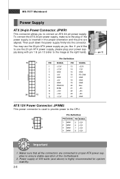
... 13 +3.3V 14 -12V 15 GND 16 PS-ON# 17 GND 18 GND 19 GND 20 Res 21 +5V 22 +5V 23 +5V 24 GND ATX 12V Power Connector: JPWM2 This power connector is used to provide power to the CPU. 5 1 8 4 Pin Definition PIN SIGNAL PIN SIGNAL 1 GND 2 GND 3 ...4 GND 5 +12V 6 +12V 7 +12V 8 +12V pin 13 pin 12 Important 1. Maker sure that all the connectors are aligned. Power supply of the motherboard. 2. MS-7577 Mainboard Power Supply ATX 24-pin Power Connector: JPWR1 This connector allows you to ensure stable operation of 450 watts (and above) is inserted in the proper...
... 13 +3.3V 14 -12V 15 GND 16 PS-ON# 17 GND 18 GND 19 GND 20 Res 21 +5V 22 +5V 23 +5V 24 GND ATX 12V Power Connector: JPWM2 This power connector is used to provide power to the CPU. 5 1 8 4 Pin Definition PIN SIGNAL PIN SIGNAL 1 GND 2 GND 3 ...4 GND 5 +12V 6 +12V 7 +12V 8 +12V pin 13 pin 12 Important 1. Maker sure that all the connectors are aligned. Power supply of the motherboard. 2. MS-7577 Mainboard Power Supply ATX 24-pin Power Connector: JPWR1 This connector allows you to ensure stable operation of 450 watts (and above) is inserted in the proper...
User Guide
Page 24
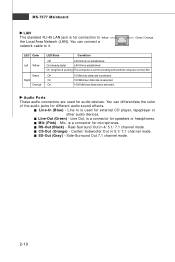
On (steady state) LAN link is selected. On 1000 Mbit/sec data rate is established. Mic (Pink) - RS-Out (Black) - MS-7577 Mainboard LAN The standard RJ-45 LAN jack is not established. Green / Orange LED Color Left Yellow Green Right Orange LED State Condition Off ...
On (steady state) LAN link is selected. On 1000 Mbit/sec data rate is established. Mic (Pink) - RS-Out (Black) - MS-7577 Mainboard LAN The standard RJ-45 LAN jack is not established. Green / Orange LED Color Left Yellow Green Right Orange LED State Condition Off ...
User Guide
Page 26
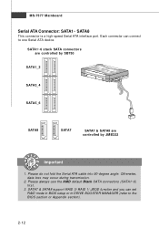
... BIOS section or Appendix section). 2-12 Please do not fold the Serial ATA cable into 90-degree angle. Otherwise, data loss may occur during transmission. 2. MS-7577 Mainboard Serial ATA Connector: SATA1~ SATA8 This connector is a high-speed Serial ATA interface port.
... BIOS section or Appendix section). 2-12 Please do not fold the Serial ATA cable into 90-degree angle. Otherwise, data loss may occur during transmission. 2. MS-7577 Mainboard Serial ATA Connector: SATA1~ SATA8 This connector is a high-speed Serial ATA interface port.
User Guide
Page 28
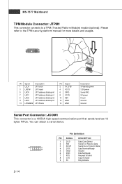
... Serial In or Receive Data Serial Out or Transmit Data Data Terminal Ready Ground Data Set Ready Request To Send Clear To Send Ring Indicate MS-7577 Mainboard TPM Module Connector: JTPM1 This connector connects to the TPM security platform manual for more details and usages. 13 1 14 2 Pin Signal Description...
... Serial In or Receive Data Serial Out or Transmit Data Data Terminal Ready Ground Data Set Ready Request To Send Clear To Send Ring Indicate MS-7577 Mainboard TPM Module Connector: JTPM1 This connector connects to the TPM security platform manual for more details and usages. 13 1 14 2 Pin Signal Description...
User Guide
Page 30
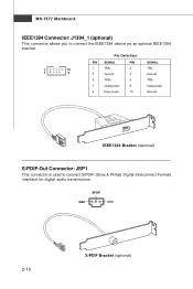
SPDIF GND VCC 2-16 S/PDIF Bracket (optional) Pin Definition 2 10 1 9 PIN SIGNAL PIN 1 TPA+ 2 3 Ground 4 5 TPB+ 6 7 Cable power 8 9 Key (no pin) 10 SIGNAL TPAGround TPBCable power Ground IEEE1394 Bracket (optional) S/PDIF-Out Connector: JSP1 This connector is used to connect the IEEE1394 device via an optional IEEE1394 bracket. MS-7577 Mainboard IEEE1394 Connector: J1394_1 (optional) This connector allows you to connect S/PDIF (Sony & Philips Digital Interconnect Format) interface for digital audio transmission.
SPDIF GND VCC 2-16 S/PDIF Bracket (optional) Pin Definition 2 10 1 9 PIN SIGNAL PIN 1 TPA+ 2 3 Ground 4 5 TPB+ 6 7 Cable power 8 9 Key (no pin) 10 SIGNAL TPAGround TPBCable power Ground IEEE1394 Bracket (optional) S/PDIF-Out Connector: JSP1 This connector is used to connect the IEEE1394 device via an optional IEEE1394 bracket. MS-7577 Mainboard IEEE1394 Connector: J1394_1 (optional) This connector allows you to connect S/PDIF (Sony & Philips Digital Interconnect Format) interface for digital audio transmission.
User Guide
Page 32
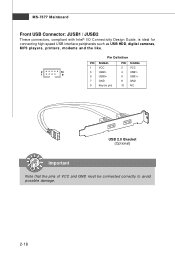
MS-7577 Mainboard Front USB Connector: JUSB1 / JUSB2 These connectors, compliant with Intel® I/O Connectivity Design Guide, is ideal for connecting high-speed USB interface peripherals such as USB HDD, digital cameras, MP3 players, printers, modems and the like. 2 10 1 9 Pin Definition PIN SIGNAL 1 VCC 3 USB0- 5 USB0+ 7 GND 9 Key (no pin) PIN SIGNAL 2 VCC 4 USB1- 6 USB1+ 8 GND 10 NC USB 2.0 Bracket (Optional) Important Note that the pins of VCC and GND must be connected correctly to avoid possible damage. 2-18
MS-7577 Mainboard Front USB Connector: JUSB1 / JUSB2 These connectors, compliant with Intel® I/O Connectivity Design Guide, is ideal for connecting high-speed USB interface peripherals such as USB HDD, digital cameras, MP3 players, printers, modems and the like. 2 10 1 9 Pin Definition PIN SIGNAL 1 VCC 3 USB0- 5 USB0+ 7 GND 9 Key (no pin) PIN SIGNAL 2 VCC 4 USB1- 6 USB1+ 8 GND 10 NC USB 2.0 Bracket (Optional) Important Note that the pins of VCC and GND must be connected correctly to avoid possible damage. 2-18
User Guide
Page 34
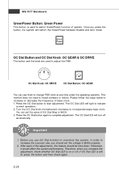
... the OC Dial button again to indicate current operation. 2. Otherwise, it would affect the system performance. The OC Dial LED will light to complete adjustment. MS-7577 Mainboard GreenPower Button: Green Power This button is still lit, press the button and then check again. 2-20 You can use OC Dial function...
... the OC Dial button again to indicate current operation. 2. Otherwise, it would affect the system performance. The OC Dial LED will light to complete adjustment. MS-7577 Mainboard GreenPower Button: Green Power This button is still lit, press the button and then check again. 2-20 You can use OC Dial function...
User Guide
Page 36
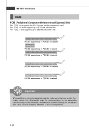
... documentation for the expansion card to PCIE 2.0 x8 speed Important When adding or removing expansion cards, make sure that you unplug the power supply first. MS-7577 Mainboard Slots PCIE (Peripheral Component Interconnect Express) Slot The PCIE slot supports the PCI Express interface expansion card. The PCIE x1 slot supports up...
... documentation for the expansion card to PCIE 2.0 x8 speed Important When adding or removing expansion cards, make sure that you unplug the power supply first. MS-7577 Mainboard Slots PCIE (Peripheral Component Interconnect Express) Slot The PCIE slot supports the PCI Express interface expansion card. The PCIE x1 slot supports up...

User Guide
Page 38
... in the Catalyst™ Control Center that needs to be enabled for more details, please consult the graphics card manual from the view drop menu. MS-7577 Mainboard 3.W hen all of the hardware and software has been properly set up and installed, reboot the system. There is a setting in Catalyst™...
... in the Catalyst™ Control Center that needs to be enabled for more details, please consult the graphics card manual from the view drop menu. MS-7577 Mainboard 3.W hen all of the hardware and software has been properly set up and installed, reboot the system. There is a setting in Catalyst™...

User Guide
Page 40
MS-7577 Mainboard LED Status Indicators NB Phase LED CPU Phase LEDs Memory Phase LEDs System Phase LEDs OC Dial LED HDD Status LED NB Phase LED Lights blue when the the NB is in 4 phase power mode. 2-26 Follow the instructions below to read. 1 LED will light blue when CPU is in 1 phase power mode. 2 LEDs will light blue when CPU is in 2 phase power mode. 3 LEDs will light blue when CPU is in 3 phase power mode. 4 LEDs will light blue when CPU is operating. CPU Phase LEDs These LEDs indicate the current CPU power phase mode.
MS-7577 Mainboard LED Status Indicators NB Phase LED CPU Phase LEDs Memory Phase LEDs System Phase LEDs OC Dial LED HDD Status LED NB Phase LED Lights blue when the the NB is in 4 phase power mode. 2-26 Follow the instructions below to read. 1 LED will light blue when CPU is in 1 phase power mode. 2 LEDs will light blue when CPU is in 2 phase power mode. 3 LEDs will light blue when CPU is in 3 phase power mode. 4 LEDs will light blue when CPU is operating. CPU Phase LEDs These LEDs indicate the current CPU power phase mode.

User Guide
Page 43
... digit refers to the model number. 6th digit refers to the chipset as I = Intel, N = nVidia, and A = AMD. 7th - 8th digit refers to the customer as MS = all standard customers. Upon boot-up, the 1st line appearing after the memory count is usually in this BIOS was released.... 3-2 MS-7577 Mainboard Entering Setup Power on the screen, press key to enter Setup. You may be slightly different from the latest BIOS and should be ...
... digit refers to the model number. 6th digit refers to the chipset as I = Intel, N = nVidia, and A = AMD. 7th - 8th digit refers to the customer as MS = all standard customers. Upon boot-up, the 1st line appearing after the memory count is usually in this BIOS was released.... 3-2 MS-7577 Mainboard Entering Setup Power on the screen, press key to enter Setup. You may be slightly different from the latest BIOS and should be ...
User Guide
Page 45
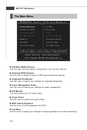
... Use this menu to set the password for basic system configurations, such as time, date etc. H/W Monitor This entry shows your settings for integrated peripherals. MS-7577 Mainboard The Main Menu Standard CMOS Features Use this menu for BIOS. Advanced BIOS Features Use this menu to specify your settings for power...
... Use this menu to set the password for basic system configurations, such as time, date etc. H/W Monitor This entry shows your settings for integrated peripherals. MS-7577 Mainboard The Main Menu Standard CMOS Features Use this menu for BIOS. Advanced BIOS Features Use this menu to specify your settings for power...
User Guide
Page 47
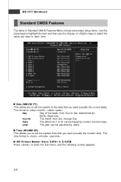
... setup items. Use the arrow keys to highlight the item and then use the or keys to set the system to Sat, determined by users. MS-7577 Mainboard Standard CMOS Features The items in each item. day Day of the week, from Jan. The format is . Date (MM:DD:YY) This...
... setup items. Use the arrow keys to highlight the item and then use the or keys to set the system to Sat, determined by users. MS-7577 Mainboard Standard CMOS Features The items in each item. day Day of the week, from Jan. The format is . Date (MM:DD:YY) This...
User Guide
Page 49
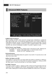
... immediately re-enable it to protect it against viruses. IOAPIC Function This field is used to enable or disable the APIC (Advanced Programmable Interrupt Controller). MS-7577 Mainboard Advanced BIOS Features BIOS Flash Protection W hen enabled, the BIOS' data cannot be changed when attempting to update the BIOS with PC2001 design...
... immediately re-enable it to protect it against viruses. IOAPIC Function This field is used to enable or disable the APIC (Advanced Programmable Interrupt Controller). MS-7577 Mainboard Advanced BIOS Features BIOS Flash Protection W hen enabled, the BIOS' data cannot be changed when attempting to update the BIOS with PC2001 design...
User Guide
Page 51
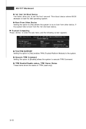
.... TPM Enable/Disable status, TPM Owner Status These items show the status of TPM (read only). 3-10 if the system fails to execute TPM Command. MS-7577 Mainboard 1st/ 2nd/ 3rd Boot Device The items allow you to set the first/ second/ Third boot device where BIOS attempts to load the...
.... TPM Enable/Disable status, TPM Owner Status These items show the status of TPM (read only). 3-10 if the system fails to execute TPM Command. MS-7577 Mainboard 1st/ 2nd/ 3rd Boot Device The items allow you to set the first/ second/ Third boot device where BIOS attempts to load the...


