User Guide
Page 9
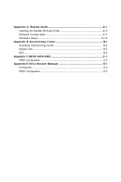
Appendix A Realtek Audio A-1 Installing the Realtek HD Audio Driver A-2 Software Configuration A-4 Hardware Setup A-19 Appendix B Overclocking Center B-1 Activating Overclocking Center B-2 System Info ...B-3 DOT ...B-5 Appendix C SB750 SATA RAID C-1 RAID Configuration C-2 Appendix D Drive Booster Manager D-1 Introduction ...D-2 RAID Configuration D-3
Appendix A Realtek Audio A-1 Installing the Realtek HD Audio Driver A-2 Software Configuration A-4 Hardware Setup A-19 Appendix B Overclocking Center B-1 Activating Overclocking Center B-2 System Info ...B-3 DOT ...B-5 Appendix C SB750 SATA RAID C-1 RAID Configuration C-2 Appendix D Drive Booster Manager D-1 Introduction ...D-2 RAID Configuration D-3
User Guide
Page 11
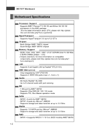
...SATA - SATA7~8 ports by JMicron® JMB362 - Supports 2 IEEE1394 ports (rear x 1, front x 1) Audio - Supports 1 E-SATA port by JMicron® JMB322 - Supports storage and data transfers at up to 3.0 Gb/s RAID - msi... DDR3 DIMMs (240pin / 1.5V) (*means overclock, for more information on compatible components, please visit http://global.msi.com.tw/index.php? func=testreport) LAN - SATA1~6 supports RAID 0/ 1/ 10/ 5 or JBOD mode ... by AMD® SB750 - MS-7577 Mainboard Motherboard Specifications Processor Support - Up to 5.2 GT/s Chipset - Chip integrated by VIA® VT6315N...
...SATA - SATA7~8 ports by JMicron® JMB362 - Supports 2 IEEE1394 ports (rear x 1, front x 1) Audio - Supports 1 E-SATA port by JMicron® JMB322 - Supports storage and data transfers at up to 3.0 Gb/s RAID - msi... DDR3 DIMMs (240pin / 1.5V) (*means overclock, for more information on compatible components, please visit http://global.msi.com.tw/index.php? func=testreport) LAN - SATA1~6 supports RAID 0/ 1/ 10/ 5 or JBOD mode ... by AMD® SB750 - MS-7577 Mainboard Motherboard Specifications Processor Support - Up to 5.2 GT/s Chipset - Chip integrated by VIA® VT6315N...
User Guide
Page 12
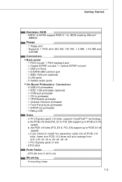
... x16 slots, these four PCIE x16 lanes will auto arrange from x16/ x16/ x0/ x0 to PCIE 2.0 x16 s peed b. Getting Started Hardware RAID - ATX (30.4cm X 24.5 cm) Mounting - 9 mounting holes 1-3 SATA7 & SATA8 support RAID 0/ 1 & JBOD mode by JMicron® JMB322 Floppy -... 2.88 MB Connectors Back panel - 1 PS/2 mouse/ 1 PS/2 keyboard port - 1 Coaxial S/PDIF-out jack / 1 Optical S/PDIF-out port - 7 USB 2.0 Ports - 1 E-SATA/USB common port - 1 IEEE 1394 port (optional) - 2 LAN jacks - 6 flexible audio jacks On-Board Pinheaders/ Connectors - 2 USB 2.0 pinheaders - 1 IEEE 1394 pinheader (optional) ...
... x16 slots, these four PCIE x16 lanes will auto arrange from x16/ x16/ x0/ x0 to PCIE 2.0 x16 s peed b. Getting Started Hardware RAID - ATX (30.4cm X 24.5 cm) Mounting - 9 mounting holes 1-3 SATA7 & SATA8 support RAID 0/ 1 & JBOD mode by JMicron® JMB322 Floppy -... 2.88 MB Connectors Back panel - 1 PS/2 mouse/ 1 PS/2 keyboard port - 1 Coaxial S/PDIF-out jack / 1 Optical S/PDIF-out port - 7 USB 2.0 Ports - 1 E-SATA/USB common port - 1 IEEE 1394 port (optional) - 2 LAN jacks - 6 flexible audio jacks On-Board Pinheaders/ Connectors - 2 USB 2.0 pinheaders - 1 IEEE 1394 pinheader (optional) ...
User Guide
Page 14
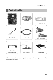
Packing Checklist Getting Started MSI motherboard MSI Driver/Utility CD Back IO Shield Power Cable SATA Cable IDE/ Floppy Cable CrossFire Video Link Cable USB Bracket User's Guide * The pictures are for reference only and may vary from the packing contents of the product you purchased. 1-5
Packing Checklist Getting Started MSI motherboard MSI Driver/Utility CD Back IO Shield Power Cable SATA Cable IDE/ Floppy Cable CrossFire Video Link Cable USB Bracket User's Guide * The pictures are for reference only and may vary from the packing contents of the product you purchased. 1-5
User Guide
Page 26
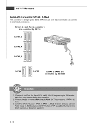
Please do not fold the Serial ATA cable into 90-degree angle. Otherwise, data loss may occur during transmission. 2. SATA1~6 stack SATA connectors are controlled by SB750 SATA1_2 SATA3_4 SATA5_6 SATA8 SATA7 SATA7 & SATA8 are controlled by JMB322 Important 1. SATA7 & SATA8 support RAID 0/ RAID 1/... JBOD function and you can connect to the BIOS section or Appendix section). 2-12 Please always use the AM D default Black SATA connectors (SATA1~6) fir s t. 3. Each connector can set RAID mode in BIOS setup or in DRIVE BOOSTER MANAGER (refer to one Serial ATA device. ...
Please do not fold the Serial ATA cable into 90-degree angle. Otherwise, data loss may occur during transmission. 2. SATA1~6 stack SATA connectors are controlled by SB750 SATA1_2 SATA3_4 SATA5_6 SATA8 SATA7 SATA7 & SATA8 are controlled by JMB322 Important 1. SATA7 & SATA8 support RAID 0/ RAID 1/... JBOD function and you can connect to the BIOS section or Appendix section). 2-12 Please always use the AM D default Black SATA connectors (SATA1~6) fir s t. 3. Each connector can set RAID mode in BIOS setup or in DRIVE BOOSTER MANAGER (refer to one Serial ATA device. ...
User Guide
Page 35
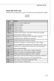
... Early CPU Initialize. Detect different devices (parallel ports, serial ports and coprocessor in CPU...etc.) 75, 78 Initialize INT 13 devices and IPL devices. (include SATA/ PATA HDD and CD/DVD ROM). 87 Enter setup screen. BIOS setup if needed . Prepare give control to OS loader (INT 19H). 00 Pass control...
... Early CPU Initialize. Detect different devices (parallel ports, serial ports and coprocessor in CPU...etc.) 75, 78 Initialize INT 13 devices and IPL devices. (include SATA/ PATA HDD and CD/DVD ROM). 87 Enter setup screen. BIOS setup if needed . Prepare give control to OS loader (INT 19H). 00 Pass control...
User Guide
Page 47
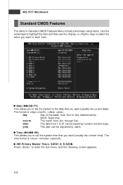
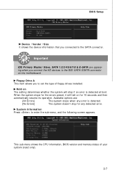
year The year can be adjusted by users. IDE Primary Master/ Slave, SATA1~8, E-SATA Press to enter the sub-menu, and the following screen appears. 3-6 Read-only. day Day of the week, from Jan. The format is . date The ...
year The year can be adjusted by users. IDE Primary Master/ Slave, SATA1~8, E-SATA Press to enter the sub-menu, and the following screen appears. 3-6 Read-only. day Day of the week, from Jan. The format is . date The ...
User Guide
Page 48
...menu shows the CPU information, BIOS version and memory status of floppy drives installed. Available options are appearing when you to the IDE/ SATA/ ESATA connector on the motherboard. W hen the system stops for the errors preset, it will halt on The setting determines whether the system will stop for 15 ... Vender / Size It shows the device information that you connected to enter the sub-menu, and the following screen appears. System Information Press to the SATA connector. Hold on for any error is detected at boot. The system doesn't stop if an error is detected.
...menu shows the CPU information, BIOS version and memory status of floppy drives installed. Available options are appearing when you to the IDE/ SATA/ ESATA connector on the motherboard. W hen the system stops for the errors preset, it will halt on The setting determines whether the system will stop for 15 ... Vender / Size It shows the device information that you connected to enter the sub-menu, and the following screen appears. System Information Press to the SATA connector. Hold on for any error is detected at boot. The system doesn't stop if an error is detected.
User Guide
Page 52
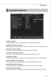
... operating system. Integrated Peripherals BIOS Setup USB Controller This setting allows you to configure E-SATA mode. LAN Option ROM This item is used to enable/disable the onboard 2nd LAN controller. E-SATA Controller Mode This item allows you to enable/disable the onboard LAN controller. Onboard 2nd... LAN Controller This item is used to enable/disable the onboard USB controller. Setting options: [AHCI] or [IDE]. 3-11 E-SATA/ HW RAID Controller This item allows you to invoke the Boot ROM of the LAN controller. Onboard LAN Controller This item is used to decide...
... operating system. Integrated Peripherals BIOS Setup USB Controller This setting allows you to configure E-SATA mode. LAN Option ROM This item is used to enable/disable the onboard 2nd LAN controller. E-SATA Controller Mode This item allows you to enable/disable the onboard LAN controller. Onboard 2nd... LAN Controller This item is used to enable/disable the onboard USB controller. Setting options: [AHCI] or [IDE]. 3-11 E-SATA/ HW RAID Controller This item allows you to invoke the Boot ROM of the LAN controller. Onboard LAN Controller This item is used to decide...
User Guide
Page 53
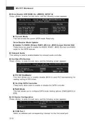
...used to enable the RAID0/ RAID1/ JBOD/ Normal (non-RAID) mode for reading/ writing to used PCI busmastering for the SATA devices. Current Mode This item shows the current SATA mode. Drive Booster M ode Update: Update To RAID0 (Stripe)/ RAID1 (Mirror)/ JBOD (Large)/ Normal Hdd These items ...you to enable/disable the onboard audio controller. I/O Device Configuration Press to enter the sub-menu and the following screen appears. On-Chip SATA Controller These items allow users to enter the sub-menu, and the following screen appears: COM Port 1 Select an address and corresponding ...
...used to enable the RAID0/ RAID1/ JBOD/ Normal (non-RAID) mode for reading/ writing to used PCI busmastering for the SATA devices. Current Mode This item shows the current SATA mode. Drive Booster M ode Update: Update To RAID0 (Stripe)/ RAID1 (Mirror)/ JBOD (Large)/ Normal Hdd These items ...you to enable/disable the onboard audio controller. I/O Device Configuration Press to enter the sub-menu and the following screen appears. On-Chip SATA Controller These items allow users to enter the sub-menu, and the following screen appears: COM Port 1 Select an address and corresponding ...

User Guide
Page 102
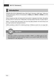
...), RAID 10 (Striping & Mirroring) & RAID 5 (striping with parity). RAID 5 defines techniques for performance and reliability. SB750 SATA RAID Appendix C SB750 SATA RAID The integrated SATA host controller separately, and support RAID function for parity data. RAID 1 makes sure data is implemented as a mirrored array whose ...segments are RAID 0 arrays. It needs at least four drives to form a RAID 1 set. C-1 SB750 SATA RAID (SATA1~6) provides support for RAID Mirroring are said to form a RAID 10. Drives configured for RAID Striping are said to two ...
...), RAID 10 (Striping & Mirroring) & RAID 5 (striping with parity). RAID 5 defines techniques for performance and reliability. SB750 SATA RAID Appendix C SB750 SATA RAID The integrated SATA host controller separately, and support RAID function for parity data. RAID 1 makes sure data is implemented as a mirrored array whose ...segments are RAID 0 arrays. It needs at least four drives to form a RAID 1 set. C-1 SB750 SATA RAID (SATA1~6) provides support for RAID Mirroring are said to form a RAID 10. Drives configured for RAID Striping are said to two ...
User Guide
Page 103
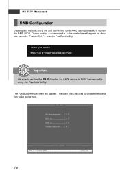
C-2 Press to enable the RAID function for about few seconds. MS-7577 Mainboard RAID Configuration Creating and deleting RAID set and performing other RAID setting operations done in BIOS before configuring the Fastbuild Utility. Important Be sure to enter FastBuild utility. The FastBuild menu screen will appear for SATA device in the RAID BIOS. During bootup, a screen similar to be performed. The Main Menu is used to choose the operation to the one below will appear.
C-2 Press to enable the RAID function for about few seconds. MS-7577 Mainboard RAID Configuration Creating and deleting RAID set and performing other RAID setting operations done in BIOS before configuring the Fastbuild Utility. Important Be sure to enter FastBuild utility. The FastBuild menu screen will appear for SATA device in the RAID BIOS. During bootup, a screen similar to be performed. The Main Menu is used to choose the operation to the one below will appear.

User Guide
Page 104
C-3 SB750 SATA RAID View Drives Assignments This window displays the model number, capacities and assignment of the drives physically attached to the SATA host adapter.
C-3 SB750 SATA RAID View Drives Assignments This window displays the model number, capacities and assignment of the drives physically attached to the SATA host adapter.

User Guide
Page 106
.... 2. The default capacity is best for most applications. If you allocate the first LD capacity manually, you want to allocate the RAID capacity manually. SB750 SATA RAID • Initialize logical drive, zero the disk drives.
.... 2. The default capacity is best for most applications. If you allocate the first LD capacity manually, you want to allocate the RAID capacity manually. SB750 SATA RAID • Initialize logical drive, zero the disk drives.
User Guide
Page 108
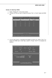
Choose a LD No you , press "Ctrl+Y" to delete the RAID set . 3. Press "Ctrl+Y" to abort it. On the next screen, a message will display to inform you want to delete and press "Del" or "Alt+D" delete the RAID set or other key to complete the deletion. SB750 SATA RAID Delete LD (Deleting RAID) 1. Select "Delete LD" on the main screen. 2. C-7
Choose a LD No you , press "Ctrl+Y" to delete the RAID set . 3. Press "Ctrl+Y" to abort it. On the next screen, a message will display to inform you want to delete and press "Del" or "Alt+D" delete the RAID set or other key to complete the deletion. SB750 SATA RAID Delete LD (Deleting RAID) 1. Select "Delete LD" on the main screen. 2. C-7
User Guide
Page 109
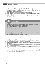
Insert the MSI DVD into the DVD-ROM drive. 2. W hen prompted, insert the floppy disk and press Enter. Press ENTER again to select "Specify Additional Device". Leave the ... copying files. Select the compatible RAID controller for yourself. 1. Note: for Windows Vista, you can copy the SATA driver to a medium (floppy/ CD/ DVD or USB) Important Please follow the instruction below to make a SATA RAID driver for 32-bit/ 64-bit version system and then press ENTER. 7. For W indows Vista: During...
Insert the MSI DVD into the DVD-ROM drive. 2. W hen prompted, insert the floppy disk and press Enter. Press ENTER again to select "Specify Additional Device". Leave the ... copying files. Select the compatible RAID controller for yourself. 1. Note: for Windows Vista, you can copy the SATA driver to a medium (floppy/ CD/ DVD or USB) Important Please follow the instruction below to make a SATA RAID driver for 32-bit/ 64-bit version system and then press ENTER. 7. For W indows Vista: During...
User Guide
Page 110
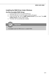
SB750 SATA RAID Installing the RAID Driver Under Windows (for Non-bootable RAID Array) 1. C-9 The AMD chipset drivers includes RAID Driver. 4. Important You must install the RAID driver to enable RAID. Insert the MSI DVD into the DVD-ROM drive. 2. The DVD will auto-run and the setup screen will be automatically installed. Under the Driver tab, click on AMD chipset drivers by your need. The driver will appear. 3.
SB750 SATA RAID Installing the RAID Driver Under Windows (for Non-bootable RAID Array) 1. C-9 The AMD chipset drivers includes RAID Driver. 4. Important You must install the RAID driver to enable RAID. Insert the MSI DVD into the DVD-ROM drive. 2. The DVD will auto-run and the setup screen will be automatically installed. Under the Driver tab, click on AMD chipset drivers by your need. The driver will appear. 3.
User Guide
Page 112
... drives for SATA ports (SATA7 & SATA8 ) on this appendix. RAID 0 breaks the data into one large disk. RAID 1 provides data redundancy by mirroring data between the hard drives and provides enhanced read performance. D-2 All the information/ volumes/ pictures listed in your system might differ from the illustrations in this motherboard. MS-7577...
... drives for SATA ports (SATA7 & SATA8 ) on this appendix. RAID 0 breaks the data into one large disk. RAID 1 provides data redundancy by mirroring data between the hard drives and provides enhanced read performance. D-2 All the information/ volumes/ pictures listed in your system might differ from the illustrations in this motherboard. MS-7577...

User Guide
Page 113
... installed, it . You may double-click on the desktop. Activating DRIVE BOOSTER MANAGER Once you to perform the following tasks of JMicron RAID. • Viewing SATA Drive information • Creating RAID Arrays • Deleting RAID Installing the DRIVE BOOSTER MANAGER Follow the procedures described below to install the Drive Booster Manager...
... installed, it . You may double-click on the desktop. Activating DRIVE BOOSTER MANAGER Once you to perform the following tasks of JMicron RAID. • Viewing SATA Drive information • Creating RAID Arrays • Deleting RAID Installing the DRIVE BOOSTER MANAGER Follow the procedures described below to install the Drive Booster Manager...

User Guide
Page 114
You may click the SATA drive item just below the item "Controller", you will find controller information. MS-7577 Mainboard View SATA Drive Information Click the "Drive Booster Information" button and the information of the window. D-4 "Drive Booster I nf or mat i on the right side of all hard disks will display on " button Or you may click the item "Controller", you will find SATA drive information.
You may click the SATA drive item just below the item "Controller", you will find controller information. MS-7577 Mainboard View SATA Drive Information Click the "Drive Booster Information" button and the information of the window. D-4 "Drive Booster I nf or mat i on the right side of all hard disks will display on " button Or you may click the item "Controller", you will find SATA drive information.
