User Guide
Page 12
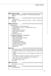
... S/PDIF-out port - 7 USB 2.0 Ports - 1 E-SATA/USB common port - 1 IEEE 1394 port (optional) - 2 LAN jacks - 6 flexible audio jacks On-Board Pinheaders/ Connectors - 2 USB 2.0 pinheaders - 1 IEEE 1394... pinheader (optional) - 1 COM port pinheader - 1 CD-in pinheader - 1 TPM Module pinheader - 1 Chassis Intrusion pinheader - 1 Front Panel Audio pinheader - 1 S/PDIF-out pinheader - 1 Debug LED Slots - 4 PCI Express gen2 x16 slots, support CrossFireXTM technology a. SATA7 & SATA8 support RAID 0/ 1 & JBOD mode by JMicron® JMB322 Floppy - 1 floppy port - ATX...
... S/PDIF-out port - 7 USB 2.0 Ports - 1 E-SATA/USB common port - 1 IEEE 1394 port (optional) - 2 LAN jacks - 6 flexible audio jacks On-Board Pinheaders/ Connectors - 2 USB 2.0 pinheaders - 1 IEEE 1394... pinheader (optional) - 1 COM port pinheader - 1 CD-in pinheader - 1 TPM Module pinheader - 1 Chassis Intrusion pinheader - 1 Front Panel Audio pinheader - 1 S/PDIF-out pinheader - 1 Debug LED Slots - 4 PCI Express gen2 x16 slots, support CrossFireXTM technology a. SATA7 & SATA8 support RAID 0/ 1 & JBOD mode by JMicron® JMB322 Floppy - 1 floppy port - ATX...
User Guide
Page 13
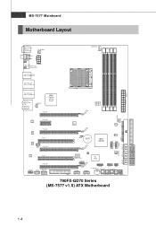
... BATT + AMD SB750 JMB322 IDE1 SATA7 SATA8 SATA3-4 S ATA1-2 SYSFAN2 FDD 1 JCI1 POS T_LED J COM1 I MM 4 Top: LAN Jack Bottom: USB ports AMD 790FX T:L i ne - O u t B:Mi c T:RS-Out M:CS-Out B:SS-Out SYSFAN4 PCI_E1 SY SFAN1 PCI_E2 LAN chip PCI_E3 LAN chip PCI1 ...USB JPWM2 Buttom: ES ATA/USB Common port Top:1394 (optional) Bottom: USB ports Top: LAN Jack Bottom: USB ports CPUFA N1 D I MM 1 D I MM 2 D I MM 3 D I /O Chip SATA5-6 JUSB1 JUS B2 OC DRIVE J TPM1 OC GEAR J FP1 JFP2 C L R_ C M OS 1 Gr een Power RESET1 POWER1 790FX-GD70 Series (MS-7577 v1.X) ATX Motherboard...
... BATT + AMD SB750 JMB322 IDE1 SATA7 SATA8 SATA3-4 S ATA1-2 SYSFAN2 FDD 1 JCI1 POS T_LED J COM1 I MM 4 Top: LAN Jack Bottom: USB ports AMD 790FX T:L i ne - O u t B:Mi c T:RS-Out M:CS-Out B:SS-Out SYSFAN4 PCI_E1 SY SFAN1 PCI_E2 LAN chip PCI_E3 LAN chip PCI1 ...USB JPWM2 Buttom: ES ATA/USB Common port Top:1394 (optional) Bottom: USB ports Top: LAN Jack Bottom: USB ports CPUFA N1 D I MM 1 D I MM 2 D I MM 3 D I /O Chip SATA5-6 JUSB1 JUS B2 OC DRIVE J TPM1 OC GEAR J FP1 JFP2 C L R_ C M OS 1 Gr een Power RESET1 POWER1 790FX-GD70 Series (MS-7577 v1.X) ATX Motherboard...
User Guide
Page 14
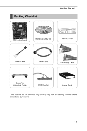
Packing Checklist Getting Started MSI motherboard MSI Driver/Utility CD Back IO Shield Power Cable SATA Cable IDE/ Floppy Cable CrossFire Video Link Cable USB Bracket User's Guide * The pictures are for reference only and may vary from the packing contents of the product you purchased. 1-5
Packing Checklist Getting Started MSI motherboard MSI Driver/Utility CD Back IO Shield Power Cable SATA Cable IDE/ Floppy Cable CrossFire Video Link Cable USB Bracket User's Guide * The pictures are for reference only and may vary from the packing contents of the product you purchased. 1-5

User Guide
Page 23
...PS/2® keyboard / mouse DIN connector is provided for a PS/2® keyboard / mouse. USB Port The USB (Universal Serial Bus) port is provided for attaching USB devices such as keyboard, mouse, or other USB-compatible devices. Back Panel Hardware Setup Coaxial M o us e S/PDIF-Out (optional) 1394 Port... LAN Keyboard USB Port LAN Line-In RS-Out Line-Out CS-Out Optical ESATA/USB USB Port USB Port USB Port S/PDIF-Out Co mm on the back panel provides connection to external speakers through a coaxial ...
...PS/2® keyboard / mouse DIN connector is provided for a PS/2® keyboard / mouse. USB Port The USB (Universal Serial Bus) port is provided for attaching USB devices such as keyboard, mouse, or other USB-compatible devices. Back Panel Hardware Setup Coaxial M o us e S/PDIF-Out (optional) 1394 Port... LAN Keyboard USB Port LAN Line-In RS-Out Line-Out CS-Out Optical ESATA/USB USB Port USB Port USB Port S/PDIF-Out Co mm on the back panel provides connection to external speakers through a coaxial ...
User Guide
Page 32
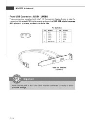
MS-7577 Mainboard Front USB Connector: JUSB1 / JUSB2 These connectors, compliant with Intel® I/O Connectivity Design Guide, is ideal for connecting high-speed USB interface peripherals such as USB HDD, digital cameras, MP3 players, printers, modems and the like. 2 10 1 9 Pin Definition PIN SIGNAL 1 VCC 3 USB0- 5 USB0+ 7 GND 9 Key (no pin) PIN SIGNAL 2 VCC 4 USB1- 6 USB1+ 8 GND 10 NC USB 2.0 Bracket (Optional) Important Note that the pins of VCC and GND must be connected correctly to avoid possible damage. 2-18
MS-7577 Mainboard Front USB Connector: JUSB1 / JUSB2 These connectors, compliant with Intel® I/O Connectivity Design Guide, is ideal for connecting high-speed USB interface peripherals such as USB HDD, digital cameras, MP3 players, printers, modems and the like. 2 10 1 9 Pin Definition PIN SIGNAL 1 VCC 3 USB0- 5 USB0+ 7 GND 9 Key (no pin) PIN SIGNAL 2 VCC 4 USB1- 6 USB1+ 8 GND 10 NC USB 2.0 Bracket (Optional) Important Note that the pins of VCC and GND must be connected correctly to avoid possible damage. 2-18
User Guide
Page 35
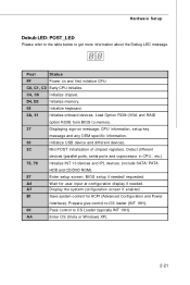
... control to OS Loader (typically INT 19H). Post Status FF Power on message, CPU information, setup key message and any OEM specific information. 38 Initialize USB device and different devices. 3C Mid POST initialization of chipset registers. Detect different devices (parallel ports, serial ports and coprocessor in CPU...etc.) 75, 78...
... control to OS Loader (typically INT 19H). Post Status FF Power on message, CPU information, setup key message and any OEM specific information. 38 Initialize USB device and different devices. 3C Mid POST initialization of chipset registers. Detect different devices (parallel ports, serial ports and coprocessor in CPU...etc.) 75, 78...
User Guide
Page 39
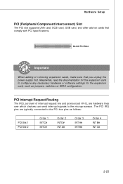
Hardware Setup PCI (Peripheral Component Interconnect) Slot The PCI slot supports LAN card, SCSI card, USB card, and other add-on cards that comply with PCI specifications. 32-bit PCI Slot Important When adding or removing expansion cards, make sure that ...
Hardware Setup PCI (Peripheral Component Interconnect) Slot The PCI slot supports LAN card, SCSI card, USB card, and other add-on cards that comply with PCI specifications. 32-bit PCI Slot Important When adding or removing expansion cards, make sure that ...
User Guide
Page 52
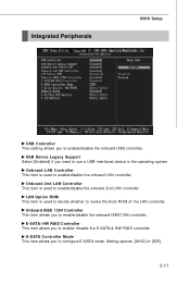
... This item is used to configure E-SATA mode. E-SATA Controller Mode This item allows you to enable/disable the onboard LAN controller. USB Device Legacy Support Select [Enabled] if you need to enable/disable the onboard 2nd LAN controller. Onboard 2nd LAN Controller This item is... used to use a USB-interfaced device in the operating system. Integrated Peripherals BIOS Setup USB Controller This setting allows you to enable/ disable the E-SATA & HW RAID controller. E-SATA/ HW RAID ...
... This item is used to configure E-SATA mode. E-SATA Controller Mode This item allows you to enable/disable the onboard LAN controller. USB Device Legacy Support Select [Enabled] if you need to enable/disable the onboard 2nd LAN controller. Onboard 2nd LAN Controller This item is... used to use a USB-interfaced device in the operating system. Integrated Peripherals BIOS Setup USB Controller This setting allows you to enable/ disable the E-SATA & HW RAID controller. E-SATA/ HW RAID ...

User Guide
Page 55
... computer is turned off. Resume By PCI Device (PM E#) W hen set to RAM) sleep state. Power Button Function This feature sets the function of the USB device to wake up event by BIOS or OS. Settings are : [OFF] Always leaves the computer in the power off button. [Suspend] W hen you to... [Enabled], the feature allows your system will appear and selectable. Wake Up Event Setup Press and the following sub-menu appears. Resume From S3 By USB Device The item allows the activity of the power button.
... computer is turned off. Resume By PCI Device (PM E#) W hen set to RAM) sleep state. Power Button Function This feature sets the function of the USB device to wake up event by BIOS or OS. Settings are : [OFF] Always leaves the computer in the power off button. [Suspend] W hen you to... [Enabled], the feature allows your system will appear and selectable. Wake Up Event Setup Press and the following sub-menu appears. Resume From S3 By USB Device The item allows the activity of the power button.

User Guide
Page 68
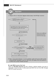
...FAT32 format only). [Disabled] Disable M-Flash function. [BIOS Update] Flash BIOS via the USB/ Storage drive directly. M-Flash BIOS Setup == BIOS Update or Load BIOS From USB drive== M-Flash function as M-Flash funcion allows you to flash BIOS from USB drive/ storage drive (FAT/ FAT32 format only), or allows the system to boot... from the BIOS file inside USB drive. It only supports particular file name, which is download from us. [Boot] After allocated particular BIOS file, system will skip MB ROM chip ...
...FAT32 format only). [Disabled] Disable M-Flash function. [BIOS Update] Flash BIOS via the USB/ Storage drive directly. M-Flash BIOS Setup == BIOS Update or Load BIOS From USB drive== M-Flash function as M-Flash funcion allows you to flash BIOS from USB drive/ storage drive (FAT/ FAT32 format only), or allows the system to boot... from the BIOS file inside USB drive. It only supports particular file name, which is download from us. [Boot] After allocated particular BIOS file, system will skip MB ROM chip ...
User Guide
Page 69
...block diagram below about the M-Flash function. Load BIOS source file from " field Save changes and exit the BIOS setup SYSTEM Restart Please check USB drive/ Storage drive/ BIOS file status and reboot the system manually again. Please refer to confirm the current M-flash process. Due to the... special design of USB/ Storage drive (FAT/FAT32 format only) in "M-Flash function as sets to [Boot] or [BIOS Update], this item to select particular BIOS file...
...block diagram below about the M-Flash function. Load BIOS source file from " field Save changes and exit the BIOS setup SYSTEM Restart Please check USB drive/ Storage drive/ BIOS file status and reboot the system manually again. Please refer to confirm the current M-flash process. Due to the... special design of USB/ Storage drive (FAT/FAT32 format only) in "M-Flash function as sets to [Boot] or [BIOS Update], this item to select particular BIOS file...

User Guide
Page 70
... a specific extend name for the BIOS file, which will be saved into the USB drive/ storage drive. Start to save file Press "Enter" and select "OK", the system will be saved into ...the USB drive/ storage drive. Save Extend File name as Please setup a specific name for the BIOS file...to save the onboard ROM chip data to save it only supports FAT/ FAT32 file system drive. Note: it to USB drive/ storage drive. BIOS Setup == BIOS Data Saving == The following fields are used to read the onboard BIOS ROM...
... a specific extend name for the BIOS file, which will be saved into the USB drive/ storage drive. Start to save file Press "Enter" and select "OK", the system will be saved into ...the USB drive/ storage drive. Save Extend File name as Please setup a specific name for the BIOS file...to save the onboard ROM chip data to save it only supports FAT/ FAT32 file system drive. Note: it to USB drive/ storage drive. BIOS Setup == BIOS Data Saving == The following fields are used to read the onboard BIOS ROM...
User Guide
Page 109
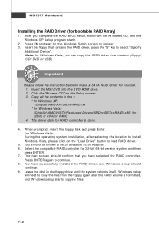
... 8. You should continue. 9. The driver disk for Windows Vista, you can copy the SATA driver to a medium (floppy/ CD/ DVD or USB) Important Please follow the instruction below to select "Specify Additional Device". W hen prompted, insert the floppy disk and press Enter. W indows setup will... all the contents in the floppy drive until the system reboots itself. Select the compatible RAID controller for bootable RAID Array) 1. Insert the MSI DVD into the DVD-ROM drive. 2. Press ENTER again to load RAID driver. 5. After you have successfully installed the RAID driver, and...
... 8. You should continue. 9. The driver disk for Windows Vista, you can copy the SATA driver to a medium (floppy/ CD/ DVD or USB) Important Please follow the instruction below to select "Specify Additional Device". W hen prompted, insert the floppy disk and press Enter. W indows setup will... all the contents in the floppy drive until the system reboots itself. Select the compatible RAID controller for bootable RAID Array) 1. Insert the MSI DVD into the DVD-ROM drive. 2. Press ENTER again to load RAID driver. 5. After you have successfully installed the RAID driver, and...


