
Operation Manual
Page 6
...is not covered by the warranty. If the transducer does "kick-up " mounting brackets. Install the transducer and route the transducer cable to the transom of damage is from the unit's location to +75 degrees Celsius). Please read over this entire installation section ...without tools. 2 For more information, contact the factory's Customer Service Department; The storage temperature for the transducer and its cable route. 3. Route the power cable from -4 degrees to +167 degrees Fahrenheit (-20 degrees to an appropriate power source and connect it to the sonar unit....
...is not covered by the warranty. If the transducer does "kick-up " mounting brackets. Install the transducer and route the transducer cable to the transom of damage is from the unit's location to +75 degrees Celsius). Please read over this entire installation section ...without tools. 2 For more information, contact the factory's Customer Service Department; The storage temperature for the transducer and its cable route. 3. Route the power cable from -4 degrees to +167 degrees Fahrenheit (-20 degrees to an appropriate power source and connect it to the sonar unit....
Operation Manual
Page 7
...frequency transom installations Tools include: two adjustable wrenches, drill, #29 (0.136") drill bit, flathead screwdriver (for connecting the power cable to it is epoxied into position, the transducer usually cannot be removed. Remember, the transducer installation is right for these instructions... part of a sonar installation. or below-waterline caulking compound. Shoot-through the transom, you prefer the option of routing the cable through hull installations Tools: these will show on your sonar unit's connectors, your boat. Selecting a Transducer Location 1. NOTE:...
...frequency transom installations Tools include: two adjustable wrenches, drill, #29 (0.136") drill bit, flathead screwdriver (for connecting the power cable to it is epoxied into position, the transducer usually cannot be removed. Remember, the transducer installation is right for these instructions... part of a sonar installation. or below-waterline caulking compound. Shoot-through the transom, you prefer the option of routing the cable through hull installations Tools: these will show on your sonar unit's connectors, your boat. Selecting a Transducer Location 1. NOTE:...

Operation Manual
Page 8
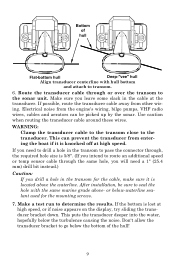
... faster than 10° Strakes Pad Vee pad hull (left); On vee hulls, try to transom near the transducer. CAUTION: Clamp the transducer cable to place the transducer where the deadrise is knocked off at high speed. Typically, a good transom location on aluminum boats is the same for ...should be displayed on the sonar's screen. This will help prevent the transducer from other wiring on the boat. If possible, route the transducer cable away from entering the boat if it doesn't interfere with the trailer or hauling of turbulence at high speed. Use caution when routing the ...
... faster than 10° Strakes Pad Vee pad hull (left); On vee hulls, try to transom near the transducer. CAUTION: Clamp the transducer cable to place the transducer where the deadrise is knocked off at high speed. Typically, a good transom location on aluminum boats is the same for ...should be displayed on the sonar's screen. This will help prevent the transducer from other wiring on the boat. If possible, route the transducer cable away from entering the boat if it doesn't interfere with the trailer or hauling of turbulence at high speed. Use caution when routing the ...

Operation Manual
Page 12
... with the bottom of the hull as shown in the water. 8 If you do, the transducer won't "kick-up or down until it with the cable passing through bracket. Side view shown at left ) and seen from above at right. 5. Attach the transducer to the ground and tighten the nut until... it strikes an object in the following figures. Transom Transom Position transducer mount on transom and mark mounting holes. Route cable over tighten the lock nut! Remove the transducer from above (right). Attaching transducer to transom.
... with the bottom of the hull as shown in the water. 8 If you do, the transducer won't "kick-up or down until it with the cable passing through bracket. Side view shown at left ) and seen from above at right. 5. Attach the transducer to the ground and tighten the nut until... it strikes an object in the following figures. Transom Transom Position transducer mount on transom and mark mounting holes. Route cable over tighten the lock nut! Remove the transducer from above (right). Attaching transducer to transom.
Operation Manual
Page 13
...size is lost at high speed, or if noise appears on the display, try sliding the transducer bracket down. If possible, route the transducer cable away from entering the boat if it is knocked off at the transducer. This can be sure to seal the hole with hull bottom and... the same hole, you drill a hole in the transom for the mounting screws. 7. Electrical noise from the engine's wiring, bilge pumps, VHF radio wires, cables and aerators can prevent the transducer from other wiring. If you need a 1" (25.4 mm) drill bit instead.) Caution: If you will need to transom. 6. ...
...size is lost at high speed, or if noise appears on the display, try sliding the transducer bracket down. If possible, route the transducer cable away from entering the boat if it is knocked off at the transducer. This can be sure to seal the hole with hull bottom and... the same hole, you drill a hole in the transom for the mounting screws. 7. Electrical noise from the engine's wiring, bilge pumps, VHF radio wires, cables and aerators can prevent the transducer from other wiring. If you need a 1" (25.4 mm) drill bit instead.) Caution: If you will need to transom. 6. ...
Operation Manual
Page 14
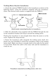
... bracket Bolt Nut Flat washer Attach motor mounting bracket to turn freely. Tighten the strap securely. 3. Make sure there is in the cable for use. Route the cable to the sonar unit and the transducer is supplied with the TMB-S through the slot in the following figure, using the hardware supplied... with the transducer. (Note: The internal tooth washer is ready for the motor to transducer. 2. Trolling Motor Bracket Installation 1. Route the transducer cable alongside the trolling motor shaft. Attach the optional TMB-S bracket to the trolling motor shaft.
... bracket Bolt Nut Flat washer Attach motor mounting bracket to turn freely. Tighten the strap securely. 3. Make sure there is in the cable for use. Route the cable to the sonar unit and the transducer is supplied with the TMB-S through the slot in the following figure, using the hardware supplied... with the transducer. (Note: The internal tooth washer is ready for the motor to transducer. 2. Trolling Motor Bracket Installation 1. Route the transducer cable alongside the trolling motor shaft. Attach the optional TMB-S bracket to the trolling motor shaft.

Operation Manual
Page 19
...connecting direct to bump the transducer while the epoxy is not long enough, splice #18 gauge wire onto it. If that you connect the power cable to use. Thoroughly stir the two compounds together until the mixture has a uniform color and consistency. Press the transducer into the epoxy, twisting and...the hull. 3. When you use . Power Connections (permanent mount only) The unit works from under the transducer face. You can occur in the power cable plug. If you 're finished, the face of the plug body along with the electrical contacts in the epoxy layer! This may result in corrosion...
...connecting direct to bump the transducer while the epoxy is not long enough, splice #18 gauge wire onto it. If that you connect the power cable to use. Thoroughly stir the two compounds together until the mixture has a uniform color and consistency. Press the transducer into the epoxy, twisting and...the hull. 3. When you use . Power Connections (permanent mount only) The unit works from under the transducer face. You can occur in the power cable plug. If you 're finished, the face of the plug body along with the electrical contacts in the epoxy layer! This may result in corrosion...

Operation Manual
Page 20
... the battery or power buss, attach one end of the fuse holder directly to the power cable, especially when the power cable is disconnected from www.lowrance.com. 16 Make sure to attach the in a dash with the optional FM-6 indash adapter kit. It uses a 3-amp fuse. Caution: Do ... reversed. This will protect both the unit and the power cable in use this product without a 3-amp fuse wired into the power cable! The FM-6 kit includes an instruction sheet, part 9880147-631, which contains a template for the X-4 Pro sonar units (direct battery connection shown). This unit has reverse...
... the battery or power buss, attach one end of the fuse holder directly to the power cable, especially when the power cable is disconnected from www.lowrance.com. 16 Make sure to attach the in a dash with the optional FM-6 indash adapter kit. It uses a 3-amp fuse. Caution: Do ... reversed. This will protect both the unit and the power cable in use this product without a 3-amp fuse wired into the power cable! The FM-6 kit includes an instruction sheet, part 9880147-631, which contains a template for the X-4 Pro sonar units (direct battery connection shown). This unit has reverse...

Operation Manual
Page 21
...hole is clearance when it's tilted for the power/transducer and accessory cables. or below-waterline caulking compound, three #10 stainless steel screws. You should be installed so that it 's a matter of the X-4 Pro when mounted on quick release bracket. Some customers, however, prefer to...(25.4 mm) hole in any convenient location, provided there is immediately under the gimbal bracket location. it covers the hole, holds the cables in position and results in the bracket's base allow wood screw or through-bolt mounting. Bracket Installation Recommended tools for this job include: ...
...hole is clearance when it's tilted for the power/transducer and accessory cables. or below-waterline caulking compound, three #10 stainless steel screws. You should be installed so that it 's a matter of the X-4 Pro when mounted on quick release bracket. Some customers, however, prefer to...(25.4 mm) hole in any convenient location, provided there is immediately under the gimbal bracket location. it covers the hole, holds the cables in position and results in the bracket's base allow wood screw or through-bolt mounting. Bracket Installation Recommended tools for this job include: ...

Operation Manual
Page 22
... Bracket These units use a quick release mounting bracket. When you and fit the cable through one hand, then tilt the unit with the cable slots facing away from you run the cables through the hole from viewer) Power/transducer cable Cable slot X-4 Pro quick release mounting bracket. Attach the unit to the dash using the three...
... Bracket These units use a quick release mounting bracket. When you and fit the cable through one hand, then tilt the unit with the cable slots facing away from you run the cables through the hole from viewer) Power/transducer cable Cable slot X-4 Pro quick release mounting bracket. Attach the unit to the dash using the three...

Operation Manual
Page 24
...slide it onto the bracket from the battery socket when the unit is turned off but still connected to mount the sonar. Route this cable through the opening Cable slot in case wall Install batteries in battery compartment (left). Close the case bottom, using the sonar in a saltwater environment, we ... the unit is not in use. This may result in corrosion of the portable power pack. To attach the unit, first plug in the cable connector. Route the cable's unit connector and about 6 inches (15.2 cm) of the bracket as shown (right). Mounting the Unit A quick-release mount is located...
...slide it onto the bracket from the battery socket when the unit is turned off but still connected to mount the sonar. Route this cable through the opening Cable slot in case wall Install batteries in battery compartment (left). Close the case bottom, using the sonar in a saltwater environment, we ... the unit is not in use. This may result in corrosion of the portable power pack. To attach the unit, first plug in the cable connector. Route the cable's unit connector and about 6 inches (15.2 cm) of the bracket as shown (right). Mounting the Unit A quick-release mount is located...

Operation Manual
Page 27
Open the case and lay it flat. Stow transducer on top of battery cover. 23 Wrap the transducer cable around the suction cup, then stow the transducer on top of the battery compartment cover. Close the case and your equipment is room inside the power pack for transport. When you're finished fishing, tilt the sonar down to the storage position. Hull Portable transducer installed on boat transom. Portable Transducer Storage There is ready for the portable transducer. Unplug the power connector from the battery compartment socket.
Open the case and lay it flat. Stow transducer on top of battery cover. 23 Wrap the transducer cable around the suction cup, then stow the transducer on top of the battery compartment cover. Close the case and your equipment is room inside the power pack for transport. When you're finished fishing, tilt the sonar down to the storage position. Hull Portable transducer installed on boat transom. Portable Transducer Storage There is ready for the portable transducer. Unplug the power connector from the battery compartment socket.
Operation Manual
Page 46
...inside the hull, be sure it is securely bonded to the unit. Unit freezes, locks up, or operates erratically: 1. Rerouting the power and transducer cables away from the boat's motor can cause the unit to negative or ground. 3. Make certain both the transducer and power connectors. Oil, dirt and ... of this manual. Electrical noise from other electrical wiring on the boat may be at least 11 volts. Make certain the power cable is wired properly. Check the cable for breaks, cuts, or pinched wires. 3. Troubleshooting If your unit is not working, or if you the trouble of returning...
...inside the hull, be sure it is securely bonded to the unit. Unit freezes, locks up, or operates erratically: 1. Rerouting the power and transducer cables away from the boat's motor can cause the unit to negative or ground. 3. Make certain both the transducer and power connectors. Oil, dirt and ... of this manual. Electrical noise from other electrical wiring on the boat may be at least 11 volts. Make certain the power cable is wired properly. Check the cable for breaks, cuts, or pinched wires. 3. Troubleshooting If your unit is not working, or if you the trouble of returning...

Operation Manual
Page 47
... down. The technical term for example, 0-100 feet) and increase the sensitivity. Try using resistor spark plugs or routing the sonar unit's power and transducer cables away from other targets. This is the most common problem if a partial arch is cavitation. 2. Use the Zoom feature. The boat must be in the...
... down. The technical term for example, 0-100 feet) and increase the sensitivity. Try using resistor spark plugs or routing the sonar unit's power and transducer cables away from other targets. This is the most common problem if a partial arch is cavitation. 2. Use the Zoom feature. The boat must be in the...
Operation Manual
Page 48
...the bilge pump and view the sonar display for the best mounting position. 44 spark plugs, alternator, or tachometer wiring. Again, routing the power cable directly to the battery helps eliminate noise problems. Make certain to keep the sonar's wires away from it from other wiring on the boat. ... manual for noise. For example, turn on the sonar display noted, then turned off . You may need to route the sonar unit's power cable directly to the battery to determine the cause. Keep doing this until all . Many novices or persons with black dots, or cause the unit operate...
...the bilge pump and view the sonar display for the best mounting position. 44 spark plugs, alternator, or tachometer wiring. Again, routing the power cable directly to the battery helps eliminate noise problems. Make certain to keep the sonar's wires away from it from other wiring on the boat. ... manual for noise. For example, turn on the sonar display noted, then turned off . You may need to route the sonar unit's power cable directly to the battery to determine the cause. Keep doing this until all . Many novices or persons with black dots, or cause the unit operate...
Operation Manual
Page 51
...was packed in transit. 3. For proper testing, include a brief note with these items. To locate a Lowrance dealer near you, visit our web site, www.lowrance.com and look for the Dealer Locator. Most quality dealers that handle marine electronic equipment or other consumer ...not be able to assist you must first receive a return authorization number from Customer Service. Lowrance does not assume responsibility for all countries To order Lowrance GPS accessories such as computer cables or MMC cards, please contact: 1) Your local marine dealer or consumer electronics store. Accessory...
...was packed in transit. 3. For proper testing, include a brief note with these items. To locate a Lowrance dealer near you, visit our web site, www.lowrance.com and look for the Dealer Locator. Most quality dealers that handle marine electronic equipment or other consumer ...not be able to assist you must first receive a return authorization number from Customer Service. Lowrance does not assume responsibility for all countries To order Lowrance GPS accessories such as computer cables or MMC cards, please contact: 1) Your local marine dealer or consumer electronics store. Accessory...

