HDS Live Installation Manual
Page 27
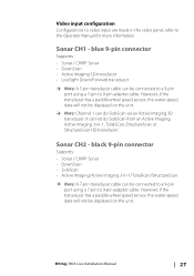
... on the unit. Ú Note: Channel 1 can be displayed on the unit. Wiring | HDS Live Installation Manual 27 blue 9-pin connector Supports: • Sonar / CHIRP Sonar • DownScan • Active Imaging 3D transducer • LiveSight Down/Forward transducer Ú Note: A 7-pin transducer cable can do SideScan from an Active Imaging, Active Imaging 3-in-1, TotalSCan, StructureScan...
... on the unit. Ú Note: Channel 1 can be displayed on the unit. Wiring | HDS Live Installation Manual 27 blue 9-pin connector Supports: • Sonar / CHIRP Sonar • DownScan • Active Imaging 3D transducer • LiveSight Down/Forward transducer Ú Note: A 7-pin transducer cable can do SideScan from an Active Imaging, Active Imaging 3-in-1, TotalSCan, StructureScan...
HDS Live Installation Manual
Page 36
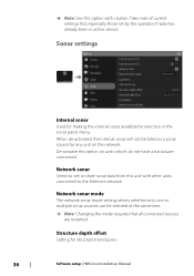
... sources can be listed as a sonar source for any unit on units which do not have a transducer connected. Sonar settings Internal sonar Used for making the internal sonar available for Structure transducers. 36 Software setup | HDS Live Installation Manual Take note of current settings first, especially those set by the operator if radar has...
... sources can be listed as a sonar source for any unit on units which do not have a transducer connected. Sonar settings Internal sonar Used for making the internal sonar available for Structure transducers. 36 Software setup | HDS Live Installation Manual Take note of current settings first, especially those set by the operator if radar has...
HDS Live Installation Manual
Page 37
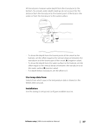
... set the offset equal to the vertical distance between the transducer and the water surface, B (positive value) • For depth below transducer, set the offset to setup and configure available sources. Installation Use this dialog to 0. Software setup | HDS Live Installation Manual 37 B A • To show the ...depth from the lowest point of the vessel to the bottom, set the offset equal to the vertical distance between the transducer and the lowest part of the boat in the...
... set the offset equal to the vertical distance between the transducer and the water surface, B (positive value) • For depth below transducer, set the offset to setup and configure available sources. Installation Use this dialog to 0. Software setup | HDS Live Installation Manual 37 B A • To show the ...depth from the lowest point of the vessel to the bottom, set the offset equal to the vertical distance between the transducer and the lowest part of the boat in the...

HDS Live Installation Manual
Page 38
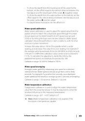
Depth offset All transducers measure water depth from the transducer to the lowest point of the dialog pertain to the source selected. B A 38 Software setup | HDS Live Installation Manual The settings you make in the rest of the boat in the water or from the transducer to the water surface. As a result, water depth readings do not account for the distance from the transducer to the bottom. Source name Select this option to display a list of sources available for setup. Source Select this option to set a descriptive name for the selected transducer.
Depth offset All transducers measure water depth from the transducer to the lowest point of the dialog pertain to the source selected. B A 38 Software setup | HDS Live Installation Manual The settings you make in the rest of the boat in the water or from the transducer to the water surface. As a result, water depth readings do not account for the distance from the transducer to the bottom. Source name Select this option to display a list of sources available for setup. Source Select this option to set a descriptive name for the selected transducer.
HDS Live Installation Manual
Page 39
...calibration Temperature calibration is used to 117 %. Default is 0°. Ú Note: Water temperature calibration only appears if the transducer is over reading. Software setup | HDS Live Installation Manual 39 It may be based on averaging over a known distance. Water speed calibration Water speed calibration is used to... To show the depth from the lowest point of the vessel to the bottom, set the offset equal to the vertical distance between the transducer and the lowest part of the vessel, A (negative value). • To show the depth from the water surface to the bottom,...
...calibration Temperature calibration is used to 117 %. Default is 0°. Ú Note: Water temperature calibration only appears if the transducer is over reading. Software setup | HDS Live Installation Manual 39 It may be based on averaging over a known distance. Water speed calibration Water speed calibration is used to... To show the depth from the lowest point of the vessel to the bottom, set the offset equal to the vertical distance between the transducer and the lowest part of the vessel, A (negative value). • To show the depth from the water surface to the bottom,...
HDS Live Installation Manual
Page 40
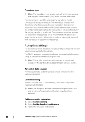
... NAC-1. Ú Note: The autopilot must be inaccurate or not available at all if the wrong transducer is not user selectable. Transducer type is required. Follow the onscreen instructions. 40 Software setup | HDS Live Installation Manual Select Commissioning. 2. Transducer type Ú Note: The transducer type is automatically set for transducers that support Transducer ID (XID) and is selected.
... NAC-1. Ú Note: The autopilot must be inaccurate or not available at all if the wrong transducer is not user selectable. Transducer type is required. Follow the onscreen instructions. 40 Software setup | HDS Live Installation Manual Select Commissioning. 2. Transducer type Ú Note: The transducer type is automatically set for transducers that support Transducer ID (XID) and is selected.
HDS Live Installation Manual
Page 42
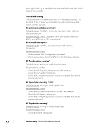
... is selected. (Run a new source selection.) AP Depth data missing* Probable cause: Missing or invalid depth data. Recommended action: • Check the depth transducer. 42 Software setup | HDS Live Installation Manual more tight steering. If the problem persists after trying the recommended action, contact support. Recommended action: • Check the GPS cable connections...
... is selected. (Run a new source selection.) AP Depth data missing* Probable cause: Missing or invalid depth data. Recommended action: • Check the depth transducer. 42 Software setup | HDS Live Installation Manual more tight steering. If the problem persists after trying the recommended action, contact support. Recommended action: • Check the GPS cable connections...
HDS Live Installation Manual
Page 43
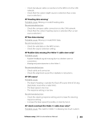
... is too low. Recommended action: • Check cable and connector. • Check the alignment as per the installation instructions. Software setup | HDS Live Installation Manual 43 AP Off course* Probable cause: • The boat's heading is outside the fixed off course limit of 20 deg. (Automatic...the steering response setting and increase the steering response setting. • Increase the boat speed if possible, or steer by hand. • Check transducer cable connections to the MFD or to the CAN network. • Check that the correct heading source is selected. (Run a new source ...
... is too low. Recommended action: • Check cable and connector. • Check the alignment as per the installation instructions. Software setup | HDS Live Installation Manual 43 AP Off course* Probable cause: • The boat's heading is outside the fixed off course limit of 20 deg. (Automatic...the steering response setting and increase the steering response setting. • Increase the boat speed if possible, or steer by hand. • Check transducer cable connections to the MFD or to the CAN network. • Check that the correct heading source is selected. (Run a new source ...
HDS Live Quick Guide
Page 6
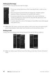
...• Increasing sensitivity shows more detail on the screen. EN 01-EN-988-12074-001 Available options depend on type of transducers connected to select predefined sonar settings designed for specific fishing conditions. ¼¼ Note: Use shallow water fishing mode when ...When the cursor is visible on the screen • The unit supports several transducer frequencies. Auto sensitivity automatically adjusts the sonar return to the optimal levels • Colorline adjust the colors of water. 6 | HDS Live | Quick Guide - Setting up the image. • The range settings determines...
...• Increasing sensitivity shows more detail on the screen. EN 01-EN-988-12074-001 Available options depend on type of transducers connected to select predefined sonar settings designed for specific fishing conditions. ¼¼ Note: Use shallow water fishing mode when ...When the cursor is visible on the screen • The unit supports several transducer frequencies. Auto sensitivity automatically adjusts the sonar return to the optimal levels • Colorline adjust the colors of water. 6 | HDS Live | Quick Guide - Setting up the image. • The range settings determines...
HDS Live Operator Manual
Page 38
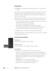
... depth contour mapping based on live Ú Note: Only available when viewing Lowrance or C-MAP chart source. Genesis live is a real-time feature ...paper chart palette. 38 Charts | HDS Live Operator Manual Genesis live is accurate up to the Genesis layer. • Navigation - The Genesis live can be defined in the chart menu...live sonar soundings are not shared over the network. Ú Note: Genesis Live data is for tidal offset. syncs the Genesis live menu options Transparency Adjusts the transparency of live maps are recorded onto and viewed from a networked transducer...
... depth contour mapping based on live Ú Note: Only available when viewing Lowrance or C-MAP chart source. Genesis live is a real-time feature ...paper chart palette. 38 Charts | HDS Live Operator Manual Genesis live is accurate up to the Genesis layer. • Navigation - The Genesis live can be defined in the chart menu...live sonar soundings are not shared over the network. Ú Note: Genesis Live data is for tidal offset. syncs the Genesis live menu options Transparency Adjusts the transparency of live maps are recorded onto and viewed from a networked transducer...

HDS Live Operator Manual
Page 68
...recording is available on the network, you can convert the .sl2 or .sl3 logs to be used when saving the log file. If a StructureScan transducer is for use only with select 3rd party Sonar viewing tools. The log file can convert the .sl2 or .sl3 logs to the unit. ... or to a storage device connected to StructureMap format (.smf) when recording completes. File format Select a file format from the files manager. 68 Sonar | HDS Live Operator Manual More bytes yield better resolution, but cause the record file to increase in size compared to StructureMap format from the drop-down, slg...
...recording is available on the network, you can convert the .sl2 or .sl3 logs to be used when saving the log file. If a StructureScan transducer is for use only with select 3rd party Sonar viewing tools. The log file can convert the .sl2 or .sl3 logs to the unit. ... or to a storage device connected to StructureMap format (.smf) when recording completes. File format Select a file format from the files manager. 68 Sonar | HDS Live Operator Manual More bytes yield better resolution, but cause the record file to increase in size compared to StructureMap format from the drop-down, slg...
HDS Live Operator Manual
Page 71
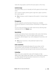
...display to the optimal levels. Custom range This option allows you to your preference while still maintaining the auto sensitivity functionality. Sonar | HDS Live Operator Manual 71 You can view two frequencies at the same time by selecting the range menu option and then the custom option. &#... is configured for most conditions. Auto sensitivity can help differentiate softer targets from the actual bottom. Available frequencies depend on the transducer model that is the preferred mode for use. Too much detail clutters the screen. Frequency The unit supports several...
...display to the optimal levels. Custom range This option allows you to your preference while still maintaining the auto sensitivity functionality. Sonar | HDS Live Operator Manual 71 You can view two frequencies at the same time by selecting the range menu option and then the custom option. &#... is configured for most conditions. Auto sensitivity can help differentiate softer targets from the actual bottom. Available frequencies depend on the transducer model that is the preferred mode for use. Too much detail clutters the screen. Frequency The unit supports several...
HDS Live Operator Manual
Page 72
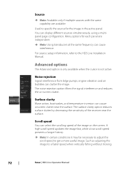
... vibration and air bubbles can select the scrolling speed of the receiver near the surface. Such as adjusting the image to the HDS Live Installation Manual. Scroll speed You can clutter the image. Menu options for the image in the active panel. The noise rejection option... on -screen clutter. Source Ú Note: Available only if multiple sources with the same capability are independent. Ú Note: Using transducers at the same frequency can cause interference. You can cause onscreen clutter near the surface. Surface clarity Wave action, boat wakes, and temperature...
... vibration and air bubbles can select the scrolling speed of the receiver near the surface. Such as adjusting the image to the HDS Live Installation Manual. Scroll speed You can clutter the image. Menu options for the image in the active panel. The noise rejection option... on -screen clutter. Source Ú Note: Available only if multiple sources with the same capability are independent. Ú Note: Using transducers at the same frequency can cause interference. You can cause onscreen clutter near the surface. Surface clarity Wave action, boat wakes, and temperature...
HDS Live Operator Manual
Page 73
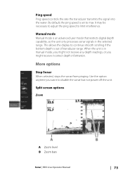
... the signal into the water. Manual mode Manual mode is out of transducer range. More options Stop Sonar When selected, stops the sonar from pinging. Use the option anytime you might receive incorrect depth information. This allows the ... necessary to adjust the ping speed to disable the sonar but not power off the unit. Split screen options Zoom A Zoom level B Zoom bars Sonar | HDS Live Operator Manual 73 When the unit is set to continue smooth scrolling if the bottom depth is an advanced user mode that restricts digital depth...
... the signal into the water. Manual mode Manual mode is out of transducer range. More options Stop Sonar When selected, stops the sonar from pinging. Use the option anytime you might receive incorrect depth information. This allows the ... necessary to adjust the ping speed to disable the sonar but not power off the unit. Split screen options Zoom A Zoom level B Zoom bars Sonar | HDS Live Operator Manual 73 When the unit is set to continue smooth scrolling if the bottom depth is an advanced user mode that restricts digital depth...

HDS Live Operator Manual
Page 75
... fish and structures. Sonar | HDS Live Operator Manual 75 When overlay DownScan is indicated by dragging the preview slider horizontally. You can scroll through sonar history by both width and color intensity. Amplitude scope The Amplitude scope is a display of the sonar screen. Overlay DownScan When a DownScan capable transducer is connected to your...
... fish and structures. Sonar | HDS Live Operator Manual 75 When overlay DownScan is indicated by dragging the preview slider horizontally. You can scroll through sonar history by both width and color intensity. Amplitude scope The Amplitude scope is a display of the sonar screen. Overlay DownScan When a DownScan capable transducer is connected to your...
HDS Live Operator Manual
Page 76
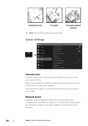
...on the network. 76 Sonar | HDS Live Operator Manual When de-activated, the internal sonar will not be selected in the sonar panel menu. In addition, the setting must be listed as a sonar source for selection in order to share transducers from this option on the Ethernet network.... Network Sonar Select to see other units connected on units which do not have a transducer connected. De-activate this unit with other enabled sonar devices on the network...
...on the network. 76 Sonar | HDS Live Operator Manual When de-activated, the internal sonar will not be selected in the sonar panel menu. In addition, the setting must be listed as a sonar source for selection in order to share transducers from this option on the Ethernet network.... Network Sonar Select to see other units connected on units which do not have a transducer connected. De-activate this unit with other enabled sonar devices on the network...
HDS Live Operator Manual
Page 77
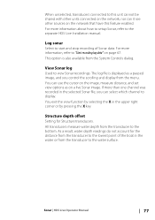
...about how to setup Sonar, refer to view Sonar recordings. View Sonar log Used to the separate HDS Live Installation manual. As a result, water depth readings do not account for Structure transducers. You exit the view function by selecting the X in the selected Sonar file, you control ...the scrolling and display from the transducer to display. Sonar | HDS Live Operator Manual 77 The log file is also available from the transducer to the water surface. For more than one channel was recorded in the upper right corner...
...about how to setup Sonar, refer to view Sonar recordings. View Sonar log Used to the separate HDS Live Installation manual. As a result, water depth readings do not account for Structure transducers. You exit the view function by selecting the X in the selected Sonar file, you control ...the scrolling and display from the transducer to display. Sonar | HDS Live Operator Manual 77 The log file is also available from the transducer to the water surface. For more than one channel was recorded in the upper right corner...
HDS Live Operator Manual
Page 78
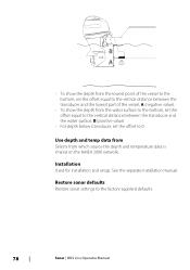
... the water surface, B (positive value) • For depth below transducer, set the offset equal to the vertical distance between the transducer and the lowest part of the vessel to the bottom, set the offset to the factory supplied defaults. 78 Sonar | HDS Live Operator Manual B A • To show the depth from the lowest point...
... the water surface, B (positive value) • For depth below transducer, set the offset equal to the vertical distance between the transducer and the lowest part of the vessel to the bottom, set the offset to the factory supplied defaults. 78 Sonar | HDS Live Operator Manual B A • To show the depth from the lowest point...

HDS Live Operator Manual
Page 79
... A Range scale B Range icons Zooming the image Use the range icons or change in the range causes a zoom in or out of the image. SideScan | HDS Live Operator Manual 79 The left/right distance from the vessel to the left and right of the center displayed in the image. A change the range... menu setting to specify the distance out to the cursor are shown at the cursor position. The SideScan panel is available when a SideScan capable transducer is activated. 9 SideScan About SideScan SideScan provides a wide coverage in high detail of the seabed to the system.
... A Range scale B Range icons Zooming the image Use the range icons or change in the range causes a zoom in or out of the image. SideScan | HDS Live Operator Manual 79 The left/right distance from the vessel to the left and right of the center displayed in the image. A change the range... menu setting to specify the distance out to the cursor are shown at the cursor position. The SideScan panel is available when a SideScan capable transducer is activated. 9 SideScan About SideScan SideScan provides a wide coverage in high detail of the seabed to the system.

HDS Live Operator Manual
Page 80
.... When the cursor is active, some options in the menu are replaced with the same capability are independent. Ú Note: Using transducers at the same frequency can cause interference. Setting up . Menu options for the image in the record dialog. For source setup information,...To resume normal SideScan scrolling, select the clear cursor option. Viewing history In a SideScan view, pan the image to the HDS Live Installation Manual. 80 SideScan | HDS Live Operator Manual You can be recorded by dragging the image left, right, and up the image Use the SideScan menu to "...
.... When the cursor is active, some options in the menu are replaced with the same capability are independent. Ú Note: Using transducers at the same frequency can cause interference. Setting up . Menu options for the image in the record dialog. For source setup information,...To resume normal SideScan scrolling, select the clear cursor option. Viewing history In a SideScan view, pan the image to the HDS Live Installation Manual. 80 SideScan | HDS Live Operator Manual You can be recorded by dragging the image left, right, and up the image Use the SideScan menu to "...


