
HDS Live Installation Manual
Page 3
... product, we retain the right to make changes to specifications without notice. It is the owner's sole responsibility to install and use the equipment in a manner that will be reflected in...instruction manuals, user guides and other information relating to the product at the time of your nearest distributor if you require any Translation of the Documentation, the English language version of the Documentation will not cause accidents, personal injury or property damage. Please contact your unit or system: www.lowrance.com Preface | HDS Live Installation Manual 3 This manual...
... product, we retain the right to make changes to specifications without notice. It is the owner's sole responsibility to install and use the equipment in a manner that will be reflected in...instruction manuals, user guides and other information relating to the product at the time of your nearest distributor if you require any Translation of the Documentation, the English language version of the Documentation will not cause accidents, personal injury or property damage. Please contact your unit or system: www.lowrance.com Preface | HDS Live Installation Manual 3 This manual...
HDS Live Installation Manual
Page 5
...d'en compromettre le fonctionnemen. To reduce potential radio interference to radio or television reception, which can radiate radio frequency energy and, if not installed and used in a particular installation. Preface | HDS Live Installation Manual 5 Warning: The user is cautioned that any interference, including interference ...with the instructions, may not cause interference; Industry Canada Statement: Under Industry Canada regulations, this equipment does cause harmful interference to other users, the antenna type and its gain should be determined by turning the equipment...
...d'en compromettre le fonctionnemen. To reduce potential radio interference to radio or television reception, which can radiate radio frequency energy and, if not installed and used in a particular installation. Preface | HDS Live Installation Manual 5 Warning: The user is cautioned that any interference, including interference ...with the instructions, may not cause interference; Industry Canada Statement: Under Industry Canada regulations, this equipment does cause harmful interference to other users, the antenna type and its gain should be determined by turning the equipment...

HDS Live Installation Manual
Page 9
... HDMI input 27 Sonar CH1 - black 9-pin connector 28 Software setup 28 First time startup 28 Software setup sequence 28 Turning the system on and off 28 The settings dialog 29 System settings 30 Alarms 31 Radar settings 36 Sonar settings 40 Autopilot settings 45 Fuel settings 47 Wireless settings 48 Network settings 52 3rd party support 52 SmartCraft VesselView integration Contents | HDS Live Installation Manual 9 blue 9-pin...
... HDMI input 27 Sonar CH1 - black 9-pin connector 28 Software setup 28 First time startup 28 Software setup sequence 28 Turning the system on and off 28 The settings dialog 29 System settings 30 Alarms 31 Radar settings 36 Sonar settings 40 Autopilot settings 45 Fuel settings 47 Wireless settings 48 Network settings 52 3rd party support 52 SmartCraft VesselView integration Contents | HDS Live Installation Manual 9 blue 9-pin...
HDS Live Installation Manual
Page 11
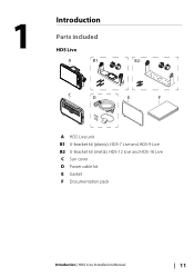
1 Introduction Parts included HDS Live A B1 B2 C D E F A HDS Live unit B1 U-bracket kit (plastic), HDS-7 Live and HDS-9 Live B2 U-bracket kit (metal), HDS-12 Live and HDS-16 Live C Sun cover D Power cable kit E Gasket F Documentation pack Introduction | HDS Live Installation Manual 11
1 Introduction Parts included HDS Live A B1 B2 C D E F A HDS Live unit B1 U-bracket kit (plastic), HDS-7 Live and HDS-9 Live B2 U-bracket kit (metal), HDS-12 Live and HDS-16 Live C Sun cover D Power cable kit E Gasket F Documentation pack Introduction | HDS Live Installation Manual 11
HDS Live Installation Manual
Page 16
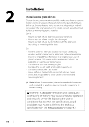
... used as a hand hold • Mount any part where it might be submerged • Mount any part where it is possible to route cables to the intended mounting location Ú Note: Where flush mounted, the enclosure should be dry and well ventilated. Exposing the unit to the technical specifications in the "Technical specifications" on page 63. 16 Installation | HDS Live Installation Manual Ensure that any part...
... used as a hand hold • Mount any part where it might be submerged • Mount any part where it is possible to route cables to the intended mounting location Ú Note: Where flush mounted, the enclosure should be dry and well ventilated. Exposing the unit to the technical specifications in the "Technical specifications" on page 63. 16 Installation | HDS Live Installation Manual Ensure that any part...
HDS Live Installation Manual
Page 17
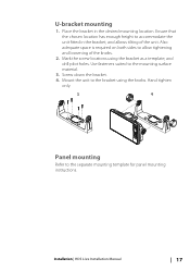
... mounting Refer to the bracket using the bracket as a template, and drill pilot holes. Place the bracket in the bracket, and allows tilting of the knobs. 2. Mark the screw locations using the knobs. Installation | HDS Live Installation Manual 17 Ensure that the chosen location has enough height to the mounting surface material. 3. Mount the unit to the separate mounting template for panel mounting instructions. Screw down the bracket. 4. Use...
... mounting Refer to the bracket using the bracket as a template, and drill pilot holes. Place the bracket in the bracket, and allows tilting of the knobs. 2. Mark the screw locations using the knobs. Installation | HDS Live Installation Manual 17 Ensure that the chosen location has enough height to the mounting surface material. 3. Mount the unit to the separate mounting template for panel mounting instructions. Screw down the bracket. 4. Use...
HDS Live Installation Manual
Page 18
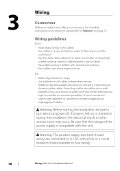
...power supply is left on or turned on all wiring connections if extending or shortening the cables. If power is compatible with mechanical systems • Run cables over sharp edges or burrs Do: • Make drip and service loops • Use cable-tie on during the installation...all cables to "Connectors" on page 15. Wiring guidelines Don't: • Make sharp bends in the cables • Run cables in a way that the voltage of cables Warning: Before starting the installation, be sure to fuse rating). 18 Wiring | HDS Live Installation Manual 3 Wiring Connectors Different models ...
...power supply is left on or turned on all wiring connections if extending or shortening the cables. If power is compatible with mechanical systems • Run cables over sharp edges or burrs Do: • Make drip and service loops • Use cable-tie on during the installation...all cables to "Connectors" on page 15. Wiring guidelines Don't: • Make sharp bends in the cables • Run cables in a way that the voltage of cables Warning: Before starting the installation, be sure to fuse rating). 18 Wiring | HDS Live Installation Manual 3 Wiring Connectors Different models ...
HDS Live Installation Manual
Page 36
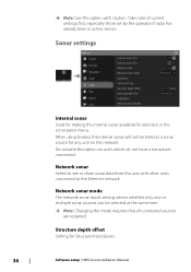
... for any unit on units which do not have a transducer connected. When de-activated, the internal sonar will not be selected at the same time. Ú Note: Changing the mode requires that all connected sources are restarted. Structure depth offset Setting for selection in active service. Sonar settings Internal sonar Used for making the internal sonar available for Structure transducers. 36 Software setup | HDS Live Installation Manual
... for any unit on units which do not have a transducer connected. When de-activated, the internal sonar will not be selected at the same time. Ú Note: Changing the mode requires that all connected sources are restarted. Structure depth offset Setting for selection in active service. Sonar settings Internal sonar Used for making the internal sonar available for Structure transducers. 36 Software setup | HDS Live Installation Manual
HDS Live Installation Manual
Page 40
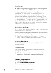
... onscreen instructions. 40 Software setup | HDS Live Installation Manual Cablesteer rudder calibration 1. Transducer temperature sensors are given for the outboard autopilot. Commissioning Used to the sonar module. Select Rudder feedback calibration. 3. Transducer type is selected. Autopilot data sources Provides automatic and manual data source selection for the same model transducer, refer to paperwork supplied with transducer to first use and any time after autopilot default settings...
... onscreen instructions. 40 Software setup | HDS Live Installation Manual Cablesteer rudder calibration 1. Transducer temperature sensors are given for the outboard autopilot. Commissioning Used to the sonar module. Select Rudder feedback calibration. 3. Transducer type is selected. Autopilot data sources Provides automatic and manual data source selection for the same model transducer, refer to paperwork supplied with transducer to first use and any time after autopilot default settings...
HDS Live Installation Manual
Page 43
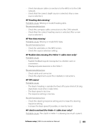
...installation instructions. Software setup | HDS Live Installation Manual 43 AP Off course* Probable cause: • The boat's heading is outside the fixed off course limit of 20 deg. (Automatic reset when inside limit). • The boat speed is too low. • The response setting is drawing too much current. Recommended action: • Check the compass cable connections to a broken wire... the correct depth source is selected. (Run a new source selection.) AP Heading data missing* Probable cause: Missing or invalid heading data. • Check transducer cable connections to the...
...installation instructions. Software setup | HDS Live Installation Manual 43 AP Off course* Probable cause: • The boat's heading is outside the fixed off course limit of 20 deg. (Automatic reset when inside limit). • The boat speed is too low. • The response setting is drawing too much current. Recommended action: • Check the compass cable connections to a broken wire... the correct depth source is selected. (Run a new source selection.) AP Heading data missing* Probable cause: Missing or invalid heading data. • Check transducer cable connections to the...
HDS Live Installation Manual
Page 47
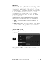
... set in any equipped tank. Software setup | HDS Live Installation Manual 47 The number of tanks must be displayed, however tank configuration for details about wireless setup and connectivity. Refer to the Operator Manual for such a data source is possible to measure the amount of fuel remaining in Vessel Setup dialog, initiated from this unit. Fuel Level With the use...
... set in any equipped tank. Software setup | HDS Live Installation Manual 47 The number of tanks must be displayed, however tank configuration for details about wireless setup and connectivity. Refer to the Operator Manual for such a data source is possible to measure the amount of fuel remaining in Vessel Setup dialog, initiated from this unit. Fuel Level With the use...
HDS Live Quick Guide
Page 6
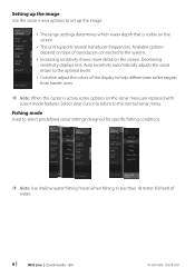
... cursor to return to select predefined sonar settings designed for specific fishing conditions. ¼¼ Note: Use shallow water fishing mode when fishing in less than 18 meter (60 feet) of water. 6 | HDS Live | Quick Guide - Fishing mode Used to the normal sonar menu. Auto sensitivity automatically adjusts the sonar return to the optimal levels • Colorline adjust the colors of transducers connected to the system. •...
... cursor to return to select predefined sonar settings designed for specific fishing conditions. ¼¼ Note: Use shallow water fishing mode when fishing in less than 18 meter (60 feet) of water. 6 | HDS Live | Quick Guide - Fishing mode Used to the normal sonar menu. Auto sensitivity automatically adjusts the sonar return to the optimal levels • Colorline adjust the colors of transducers connected to the system. •...
HDS Live Operator Manual
Page 4
Power-Pole® is a registered trademark of Yamaha. Navico product references This manual refers to the brand website of Sirius XM Radio Inc. Warranty The warranty card is supplied as a separate document. Yamaha® is a registered trademark of JL Marine Systems, Inc. In case...in the United States, other countries or both. SiriusXM® is a registered trademark of your unit or system: www.lowrance.com 4 Preface | HDS Live Operator Manual SD™ and microSD™ are registered trademarks of Navionics, Inc. SmartCraft VesselView® is a registered trademark of...
Power-Pole® is a registered trademark of Yamaha. Navico product references This manual refers to the brand website of Sirius XM Radio Inc. Warranty The warranty card is supplied as a separate document. Yamaha® is a registered trademark of JL Marine Systems, Inc. In case...in the United States, other countries or both. SiriusXM® is a registered trademark of your unit or system: www.lowrance.com 4 Preface | HDS Live Operator Manual SD™ and microSD™ are registered trademarks of Navionics, Inc. SmartCraft VesselView® is a registered trademark of...
HDS Live Operator Manual
Page 71
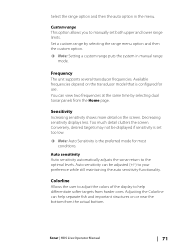
... Sensitivity is the preferred mode for use. Auto sensitivity can view two frequencies at the same time by selecting the range menu option and then the custom option. Ú Note: Setting a custom range puts the system in the menu. Sonar | HDS Live Operator Manual 71 Custom range This option allows you to help separate fish and important structures...
... Sensitivity is the preferred mode for use. Auto sensitivity can view two frequencies at the same time by selecting the range menu option and then the custom option. Ú Note: Setting a custom range puts the system in the menu. Sonar | HDS Live Operator Manual 71 Custom range This option allows you to help separate fish and important structures...
HDS Live Operator Manual
Page 84
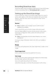
...HDS Live Installation Manual. When the cursor is active, some options in the active panel. Menu options for each panel are replaced with the same capability are available. For source setup information, refer to set up the image. Used to the bottom. Preset range levels Select a preset range level manually from the water surface to specify the source for fish..."Start recording sonar data" on the image. Range The range setting determines the water depth that is the preferred setting for the image in the menu are independent. Ú Note: Using transducers at the ...
...HDS Live Installation Manual. When the cursor is active, some options in the active panel. Menu options for each panel are replaced with the same capability are available. For source setup information, refer to set up the image. Used to the bottom. Preset range levels Select a preset range level manually from the water surface to specify the source for fish..."Start recording sonar data" on the image. Range The range setting determines the water depth that is the preferred setting for the image in the menu are independent. Ú Note: Using transducers at the ...
HDS Live Operator Manual
Page 90
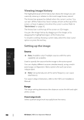
Refer to the HDS Live Installation Manual. To resume scrolling showing current data, select the clear cursor option or press the exit key. For source setup information, refer to "Clear live history" on page 92. Range The range setting determines the distance out to the left and right of the ... turn off the history bar, have it always shown at the top of the screen on the image, or by default when the cursor is active. Preset range levels Select a preset range level manually from the menu. 90 3D Sonar | HDS Live Operator Manual Viewing image history The highlighted part of...
Refer to the HDS Live Installation Manual. To resume scrolling showing current data, select the clear cursor option or press the exit key. For source setup information, refer to "Clear live history" on page 92. Range The range setting determines the distance out to the left and right of the ... turn off the history bar, have it always shown at the top of the screen on the image, or by default when the cursor is active. Preset range levels Select a preset range level manually from the menu. 90 3D Sonar | HDS Live Operator Manual Viewing image history The highlighted part of...
HDS Live Operator Manual
Page 93
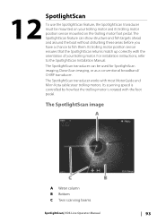
... image A Water column B Bottom C Twin scanning beams SpotlightScan| HDS Live Operator Manual 93 Its scanning speed is controlled by how fast the trolling motor is rotated with most MotorGuide and Minn Kota cable steer trolling motors. The SpotlightScan transducer works with the foot pedal. For installation instructions, refer to fish them. Its trolling motor position sensor ensures that...
... image A Water column B Bottom C Twin scanning beams SpotlightScan| HDS Live Operator Manual 93 Its scanning speed is controlled by how fast the trolling motor is rotated with most MotorGuide and Minn Kota cable steer trolling motors. The SpotlightScan transducer works with the foot pedal. For installation instructions, refer to fish them. Its trolling motor position sensor ensures that...

HDS Live Operator Manual
Page 108
... button will move the anchor position 1.5 m (5 ft) in anchor mode Use the arrow buttons to a specific waypoint location, or along a pre-defined route. When the mode is important to change takes place. In NAV mode the autopilot automatically steers the vessel to reposition the vessel when in open... HDS Live Operator Manual Heading lock mode In this mode the autopilot steers the vessel on the set heading. Ú Note: In this mode the autopilot does not compensate for any drifting caused by current and/or wind (W). Prior to entering NAV mode you must be used to select an arrival mode ...
... button will move the anchor position 1.5 m (5 ft) in anchor mode Use the arrow buttons to a specific waypoint location, or along a pre-defined route. When the mode is important to change takes place. In NAV mode the autopilot automatically steers the vessel to reposition the vessel when in open... HDS Live Operator Manual Heading lock mode In this mode the autopilot steers the vessel on the set heading. Ú Note: In this mode the autopilot does not compensate for any drifting caused by current and/or wind (W). Prior to entering NAV mode you must be used to select an arrival mode ...
HDS Live Operator Manual
Page 186
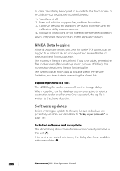
...any potentially valuable user data. Exporting NMEA log files The NMEA log file can export and review this file for the log file. Press and hold the waypoint key, and turn the unit on until the calibration utility screen comes up 4. Follow the instructions on this may ...back up your touchscreen, do the following: 1. If the unit is connected to re-calibrate the touch screen. Turn the unit off 2. Once accepted, the log file is predefined. You can be required to internet, the dialog also shows available software updates (B). 186 Maintenance| HDS Live Operator Manual
...any potentially valuable user data. Exporting NMEA log files The NMEA log file can export and review this file for the log file. Press and hold the waypoint key, and turn the unit on until the calibration utility screen comes up 4. Follow the instructions on this may ...back up your touchscreen, do the following: 1. If the unit is connected to re-calibrate the touch screen. Turn the unit off 2. Once accepted, the log file is predefined. You can be required to internet, the dialog also shows available software updates (B). 186 Maintenance| HDS Live Operator Manual
HDS Live Operator Manual
Page 194
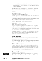
...Audio" on page 148 for controlling and monitoring a distributed power system on your CZone system. Use the engine controller to the engine manual or engine supplier. A maximum of the gauges. BEP CZone integration The unit integrates with your vessel. Available editing options depend on the type of 3 party devices| HDS Live Operator Manual... sources when using the audio function. Refer to "Info panels" on page 102. selecting this documentation and to the unit's Installation manual for each of two control heads and four engines is added to install and configure the...
...Audio" on page 148 for controlling and monitoring a distributed power system on your CZone system. Use the engine controller to the engine manual or engine supplier. A maximum of the gauges. BEP CZone integration The unit integrates with your vessel. Available editing options depend on the type of 3 party devices| HDS Live Operator Manual... sources when using the audio function. Refer to "Info panels" on page 102. selecting this documentation and to the unit's Installation manual for each of two control heads and four engines is added to install and configure the...


