Declaration of Conformity
Page 1
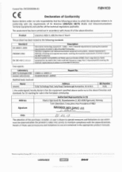
...limitations to use which must be used in the 1 GHz to use are contained in conformity with the above directives. Product Lowrance HDS-7, HDS 7m Gen 2 Touch This product has been tested to the following product to the above directive. Navico Logistics Europe BV I Donker Duyvisweq 56 ...Farnborough Hampshire. Control No. DEC20130206-01. navico CE Declaration of the purchaser, installer, or user is in the appropriate product manuals. The assessment has been carried out in the European community. Details of the above Directive and standards for CE marking for sale...
...limitations to use which must be used in the 1 GHz to use are contained in conformity with the above directives. Product Lowrance HDS-7, HDS 7m Gen 2 Touch This product has been tested to the following product to the above directive. Navico Logistics Europe BV I Donker Duyvisweq 56 ...Farnborough Hampshire. Control No. DEC20130206-01. navico CE Declaration of the purchaser, installer, or user is in the appropriate product manuals. The assessment has been carried out in the European community. Details of the above Directive and standards for CE marking for sale...

Installation Manual
Page 1
HDS Gen2 Touch Installation Manual ENGLISH lowrance.com
HDS Gen2 Touch Installation Manual ENGLISH lowrance.com
Installation Manual
Page 3
...ALL LIABILITY FOR ANY USE OF THIS PRODUCT IN A WAY THAT MAY CAUSE ACCIDENTS, DAMAGE OR THAT MAY VIOLATE THE LAW. This manual represents the product as at any further assistance. and E.E.A. | 1 Preface As Navico is continuously improving this product is supplied as ...a separate document. Please contact your display or system: www.lowrance.com Declarations and conformance This equipment is intended for observing safe boating practices. Governing Language: This statement, any instruction manuals, user guides and other information relating to the product (Documentation) may ...
...ALL LIABILITY FOR ANY USE OF THIS PRODUCT IN A WAY THAT MAY CAUSE ACCIDENTS, DAMAGE OR THAT MAY VIOLATE THE LAW. This manual represents the product as at any further assistance. and E.E.A. | 1 Preface As Navico is continuously improving this product is supplied as ...a separate document. Please contact your display or system: www.lowrance.com Declarations and conformance This equipment is intended for observing safe boating practices. Governing Language: This statement, any instruction manuals, user guides and other information relating to the product (Documentation) may ...
Installation Manual
Page 5
... a trademark of Kongsberg Maritime AS Company registered in the US and other countries and is being used under license. • 'HDS', 'StructureScan', 'Navico', 'Lowrance', 'SonicHub', 'SimNet' and 'Skimmer' are trademarks of Navico, registered in the US and other countries. 'InsightHD', 'Broadband ...manual does not cover basic background information about how equipment such as follows: ¼¼ Note: Used to draw the reader's attention to warn personnel that requires special attention from the reader is a reference guide for installing the Lowrance HDS-7, HDS-9, and HDS-12 Gen2 Touch...
... a trademark of Kongsberg Maritime AS Company registered in the US and other countries and is being used under license. • 'HDS', 'StructureScan', 'Navico', 'Lowrance', 'SonicHub', 'SimNet' and 'Skimmer' are trademarks of Navico, registered in the US and other countries. 'InsightHD', 'Broadband ...manual does not cover basic background information about how equipment such as follows: ¼¼ Note: Used to draw the reader's attention to warn personnel that requires special attention from the reader is a reference guide for installing the Lowrance HDS-7, HDS-9, and HDS-12 Gen2 Touch...
Installation Manual
Page 8
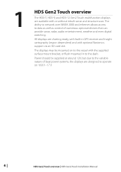
... cartography (region dependent) and with optional Navionics support via an SD card slot. 1 HDS Gen2 Touch overview The HDS-7, HDS-9, and HDS-12 Gen2 Touch multifunction displays are charting ready, with built-in to the dash. Power should be mounted on 10.8 V - 17 V. 6 | HDS Gen2 Touch overview | HDS Gen2 Touch Installation Manual All displays are available with or without inbuilt sonar and structure scan. The...
... cartography (region dependent) and with optional Navionics support via an SD card slot. 1 HDS Gen2 Touch overview The HDS-7, HDS-9, and HDS-12 Gen2 Touch multifunction displays are charting ready, with built-in to the dash. Power should be mounted on 10.8 V - 17 V. 6 | HDS Gen2 Touch overview | HDS Gen2 Touch Installation Manual All displays are available with or without inbuilt sonar and structure scan. The...
Installation Manual
Page 9
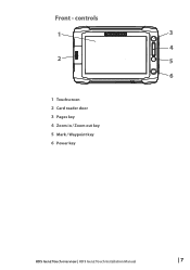
Front - controls 1 3 4 2 5 6 1 Touchscreen 2 Card reader door 3 Pages key 4 Zoom in / Zoom out key 5 Mark / Waypoint key 6 Power key HDS Gen2 Touch overview | HDS Gen2 Touch Installation Manual | 7
Front - controls 1 3 4 2 5 6 1 Touchscreen 2 Card reader door 3 Pages key 4 Zoom in / Zoom out key 5 Mark / Waypoint key 6 Power key HDS Gen2 Touch overview | HDS Gen2 Touch Installation Manual | 7
Installation Manual
Page 10
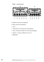
connects to LSS-2 HD Transducer 3 Power - also video for HDS-9 & 12, with optional adaptor 4 Ethernet - two ports on HDS-9 & 12, one on 7 5 NMEA 2000 8 | HDS Gen2 Touch overview | HDS Gen2 Touch Installation Manual Rear - connectors A B 1 2 3445 451 2 3 A HDS-9 & 12 connector arrangement B HDS-7 connector arrangement 1 Sonar 2 StructureScan -
connects to LSS-2 HD Transducer 3 Power - also video for HDS-9 & 12, with optional adaptor 4 Ethernet - two ports on HDS-9 & 12, one on 7 5 NMEA 2000 8 | HDS Gen2 Touch overview | HDS Gen2 Touch Installation Manual Rear - connectors A B 1 2 3445 451 2 3 A HDS-9 & 12 connector arrangement B HDS-7 connector arrangement 1 Sonar 2 StructureScan -
Installation Manual
Page 11
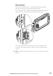
The card reader door should always be shut immediately after inserting or removing a card, in order to the left, then pulling forward from the left side. The card reader door is opened by lightly pressing and sliding the door to prevent possible water ingress. ¼¼ Note: The HDS-9 and 12 Displays have two card readers, the HDS-7 has one. SD card slot Used for optional Navionics or InsightHD chart data, software updates, transfer of user data and system backup. HDS Gen2 Touch overview | HDS Gen2 Touch Installation Manual | 9
The card reader door should always be shut immediately after inserting or removing a card, in order to the left, then pulling forward from the left side. The card reader door is opened by lightly pressing and sliding the door to prevent possible water ingress. ¼¼ Note: The HDS-9 and 12 Displays have two card readers, the HDS-7 has one. SD card slot Used for optional Navionics or InsightHD chart data, software updates, transfer of user data and system backup. HDS Gen2 Touch overview | HDS Gen2 Touch Installation Manual | 9
Installation Manual
Page 12
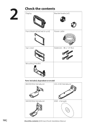
manuals 10 | Check the contents | HDS Gen2 Touch Installation Manual 2 Check the contents Display Bracket knobs (x2) Front Bezel (attached to unit) Power cable Sun cover Fasteners - #6 x 1.5" (4x) Mounting bracket Parts Included, dependent on model 83/200 KHz transducer LSS-2 HD transducer 50/200 KHz transducer DVD -
manuals 10 | Check the contents | HDS Gen2 Touch Installation Manual 2 Check the contents Display Bracket knobs (x2) Front Bezel (attached to unit) Power cable Sun cover Fasteners - #6 x 1.5" (4x) Mounting bracket Parts Included, dependent on model 83/200 KHz transducer LSS-2 HD transducer 50/200 KHz transducer DVD -
Installation Manual
Page 13
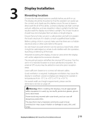
... safety equipment is required. Do not mount any holes cut . The mounting location will affect the internal GPS receiver. Lowrance displays are high-contrast and anti-reflective, and are viewable in doubt, consult a qualified boat builder. The chosen location...best results install the display out of the cables. Lowrance displays are designed to connect all of direct sunlight. Leave sufficient clearance to operate in temperatures from windows or bright objects. Display Installation | HDS Gen2 Touch Installation Manual | 11 The display should have minimal glare from...
... safety equipment is required. Do not mount any holes cut . The mounting location will affect the internal GPS receiver. Lowrance displays are high-contrast and anti-reflective, and are viewable in doubt, consult a qualified boat builder. The chosen location...best results install the display out of the cables. Lowrance displays are designed to connect all of direct sunlight. Leave sufficient clearance to operate in temperatures from windows or bright objects. Display Installation | HDS Gen2 Touch Installation Manual | 11 The display should have minimal glare from...
Installation Manual
Page 14
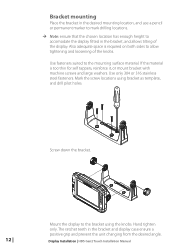
..., and allows tilting of the knobs. Screw down the bracket. 12 | Mount the display to allow tightening and loosening of the display. Display Installation | HDS Gen2 Touch Installation Manual Bracket mounting Place the bracket in the desired mounting location, and use a pencil or permanent marker to mark drilling locations. ¼¼ Note: ensure that...
..., and allows tilting of the knobs. Screw down the bracket. 12 | Mount the display to allow tightening and loosening of the display. Display Installation | HDS Gen2 Touch Installation Manual Bracket mounting Place the bracket in the desired mounting location, and use a pencil or permanent marker to mark drilling locations. ¼¼ Note: ensure that...
Installation Manual
Page 15
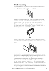
... vessel may be of a 'neutral cure' type to prevent damage to the plastics. Once screws are closest to the card reader door. Display Installation | HDS Gen2 Touch Installation Manual | 13 Remove the bezel from the display, using an appropriate saw, cut through the template and mounting surface, along the dotted line bordering the shaded...
... vessel may be of a 'neutral cure' type to prevent damage to the plastics. Once screws are closest to the card reader door. Display Installation | HDS Gen2 Touch Installation Manual | 13 Remove the bezel from the display, using an appropriate saw, cut through the template and mounting surface, along the dotted line bordering the shaded...
Installation Manual
Page 16
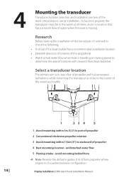
...; Establish direction of rotation of the propeller(s) • Watch actual water flow when boat is travelling at all times, and in sonar installation. Display Installation | HDS Gen2 Touch Installation Manual avoid mounting behind here ¼¼ Note: Reverse the distance guides (1 & 3) from propeller where engine is moving. Research Before starting the installation of the...
...; Establish direction of rotation of the propeller(s) • Watch actual water flow when boat is travelling at all times, and in sonar installation. Display Installation | HDS Gen2 Touch Installation Manual avoid mounting behind here ¼¼ Note: Reverse the distance guides (1 & 3) from propeller where engine is moving. Research Before starting the installation of the...
Installation Manual
Page 17
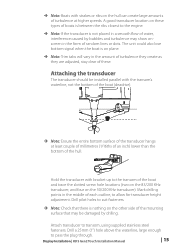
... that may show onscreen in the middle of these types of boats is between the ribs closest to allow for transducer height adjustment. Display Installation | HDS Gen2 Touch Installation Manual | 15 Hold the transducer with the transom's waterline, not the bottom of the boat (deadrise). ¼¼ Note: Ensure the entire bottom surface of...
... that may show onscreen in the middle of these types of boats is between the ribs closest to allow for transducer height adjustment. Display Installation | HDS Gen2 Touch Installation Manual | 15 Hold the transducer with the transom's waterline, not the bottom of the boat (deadrise). ¼¼ Note: Ensure the entire bottom surface of...
Installation Manual
Page 18
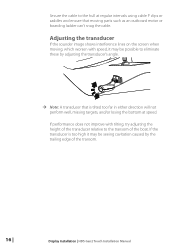
... using cable P clips or saddles and ensure that is too high it may be possible to the transom of the transom. 16 | Display Installation | HDS Gen2 Touch Installation Manual Adjusting the transducer If the sounder image shows interference lines on the screen when moving, which worsen with tilting, try adjusting the height of the...
... using cable P clips or saddles and ensure that is too high it may be possible to the transom of the transom. 16 | Display Installation | HDS Gen2 Touch Installation Manual Adjusting the transducer If the sounder image shows interference lines on the screen when moving, which worsen with tilting, try adjusting the height of the...
Installation Manual
Page 19
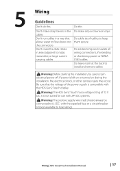
... not suited for use with 24V DC systems. ! Warning: Before starting the installation, be connected to (+) DC with the HDS Gen2 Touch display ! Warning: The positive supply wire (red) should always be sure to turn electrical power off. Be sure that allows... it is left on or turned on during the installation, fire, electrical shock, or other serious injury may occur. Wiring | HDS Gen2 Touch Installation Manual | 17 Warning: The HDS Gen2 Touch has a voltage rating of the power supply is compatible with the supplied fuse or a circuit breaker (closest available to fuse rating)....
... not suited for use with 24V DC systems. ! Warning: Before starting the installation, be connected to (+) DC with the HDS Gen2 Touch display ! Warning: The positive supply wire (red) should always be sure to turn electrical power off. Be sure that allows... it is left on or turned on during the installation, fire, electrical shock, or other serious injury may occur. Wiring | HDS Gen2 Touch Installation Manual | 17 Warning: The HDS Gen2 Touch has a voltage rating of the power supply is compatible with the supplied fuse or a circuit breaker (closest available to fuse rating)....
Installation Manual
Page 20
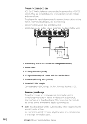
.... This means that the modules are protected against reverse polarity, under voltage and over voltage. Power connection HDS Gen2 Touch displays are designed to be put in standby, when triggered by a 12 V DC system. The thickest...HDS display rear (9 & 12 connector arrangement shown) 2 Power cable 3 12 V negative wire (black) 4 12 V positive wire (red) shown with fuse holder fitted 5 Accessory Wake Up wire (yellow) 6 Vessel's 12 V DC supply Connect red to (-) DC. The plug of Navico modules such as SonicHub, StructureScan, and Broadband radar. Wiring | HDS Gen2 Touch Installation Manual...
.... This means that the modules are protected against reverse polarity, under voltage and over voltage. Power connection HDS Gen2 Touch displays are designed to be put in standby, when triggered by a 12 V DC system. The thickest...HDS display rear (9 & 12 connector arrangement shown) 2 Power cable 3 12 V negative wire (black) 4 12 V positive wire (red) shown with fuse holder fitted 5 Accessory Wake Up wire (yellow) 6 Vessel's 12 V DC supply Connect red to (-) DC. The plug of Navico modules such as SonicHub, StructureScan, and Broadband radar. Wiring | HDS Gen2 Touch Installation Manual...
Installation Manual
Page 21
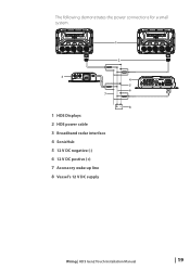
The following demonstrates the power connections for a small system. 1 2 3 7 1 HDS Displays 2 HDS power cable 3 Broadband radar interface 4 SonicHub 5 12 V DC negative (-) 6 12 V DC postive (+) 7 Accessory wake up line 8 Vessel's 12 V DC supply 4 5 6 +_ 8 Wiring | HDS Gen2 Touch Installation Manual | 19
The following demonstrates the power connections for a small system. 1 2 3 7 1 HDS Displays 2 HDS power cable 3 Broadband radar interface 4 SonicHub 5 12 V DC negative (-) 6 12 V DC postive (+) 7 Accessory wake up line 8 Vessel's 12 V DC supply 4 5 6 +_ 8 Wiring | HDS Gen2 Touch Installation Manual | 19
Installation Manual
Page 22
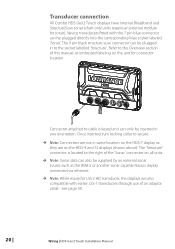
... display connected via ethernet. ¼¼ Note: While made for LSS-2 HD transducer, the displays are on the unit for sonar). see page 30. 20 | Wiring | HDS Gen2 Touch Installation Manual The 'Structure' connector is keyed and can be inserted in one orientation. ...Transducer connection All Combo HDS Gen2 Touch displays have internal Broadband and StructureScan sonar (chart only units require an external...
... display connected via ethernet. ¼¼ Note: While made for LSS-2 HD transducer, the displays are on the unit for sonar). see page 30. 20 | Wiring | HDS Gen2 Touch Installation Manual The 'Structure' connector is keyed and can be inserted in one orientation. ...Transducer connection All Combo HDS Gen2 Touch displays have internal Broadband and StructureScan sonar (chart only units require an external...

Installation Manual
Page 23
... on the NEP-2, it is auto sensing, meaning that the unit can connect to a HDS-9 or HDS-12 display, use of a crossover cable or switch. Wiring | HDS Gen2 Touch Installation Manual | 21 Connecting directly to a single device The ethernet port is possible to link two ...or more than one ethernet device to a HDS-7 display, or two devices to one ethernet port, whereas the HDS-9 and 12 displays have a locking ...
... on the NEP-2, it is auto sensing, meaning that the unit can connect to a HDS-9 or HDS-12 display, use of a crossover cable or switch. Wiring | HDS Gen2 Touch Installation Manual | 21 Connecting directly to a single device The ethernet port is possible to link two ...or more than one ethernet device to a HDS-7 display, or two devices to one ethernet port, whereas the HDS-9 and 12 displays have a locking ...

