Declaration of Conformity
Page 1
... G AS Date 2zi--- Short range devices; GU14 OLX. The assessment has been carried out in accordance with the above directives. Product Lowrance HDS-7, HDS 7m Gen 2 Touch This product has been tested to the following product to which must be used in the 1 GHz to use are contained in the ...European community. e 2_ /3 The attention of the above Directive and standards for CE marking for sale in the appropriate product manuals. Notified...
... G AS Date 2zi--- Short range devices; GU14 OLX. The assessment has been carried out in accordance with the above directives. Product Lowrance HDS-7, HDS 7m Gen 2 Touch This product has been tested to the following product to which must be used in the 1 GHz to use are contained in the ...European community. e 2_ /3 The attention of the above Directive and standards for CE marking for sale in the appropriate product manuals. Notified...

Installation Manual
Page 1
HDS Gen2 Touch Installation Manual ENGLISH lowrance.com
HDS Gen2 Touch Installation Manual ENGLISH lowrance.com
Installation Manual
Page 3
...personal injury or property damage. This manual represents the product as a separate document. Governing Language: This statement, any instruction manuals, user guides and other information relating to the product (Documentation) may not be reflected in this version of the manual. Navico Holding AS and its ...subsidiaries, branches and affiliates reserve the right to make changes to the product at the time of printing. Please contact your display or system: www.lowrance.com Declarations and conformance This equipment ...
...personal injury or property damage. This manual represents the product as a separate document. Governing Language: This statement, any instruction manuals, user guides and other information relating to the product (Documentation) may not be reflected in this version of the manual. Navico Holding AS and its ...subsidiaries, branches and affiliates reserve the right to make changes to the product at the time of printing. Please contact your display or system: www.lowrance.com Declarations and conformance This equipment ...
Installation Manual
Page 5
...sounders and AIS work. Warning: Used when it is a reference guide for installing the Lowrance HDS-7, HDS-9, and HDS-12 Gen2 Touch system. About this manual This manual is necessary to warn personnel that requires special attention from the reader is being used under license.... • 'HDS', 'StructureScan', 'Navico', 'Lowrance', 'SonicHub', 'SimNet' and 'Skimmer' are trademarks of Navico, registered in the US and other ...
...sounders and AIS work. Warning: Used when it is a reference guide for installing the Lowrance HDS-7, HDS-9, and HDS-12 Gen2 Touch system. About this manual This manual is necessary to warn personnel that requires special attention from the reader is being used under license.... • 'HDS', 'StructureScan', 'Navico', 'Lowrance', 'SonicHub', 'SimNet' and 'Skimmer' are trademarks of Navico, registered in the US and other ...

Installation Manual
Page 8
... mounted on 10.8 V - 17 V. 6 | HDS Gen2 Touch overview | HDS Gen2 Touch Installation Manual All displays are designed to operate on to the vessel with the supplied surface mount bracket, or flush mounted in GPS receiver and Insight cartography (region dependent) and with or without inbuilt sonar and structure scan. 1 HDS Gen2 Touch overview The HDS-7, HDS-9, and HDS-12 Gen2 Touch multifunction displays are available...
... mounted on 10.8 V - 17 V. 6 | HDS Gen2 Touch overview | HDS Gen2 Touch Installation Manual All displays are designed to operate on to the vessel with the supplied surface mount bracket, or flush mounted in GPS receiver and Insight cartography (region dependent) and with or without inbuilt sonar and structure scan. 1 HDS Gen2 Touch overview The HDS-7, HDS-9, and HDS-12 Gen2 Touch multifunction displays are available...
Installation Manual
Page 9
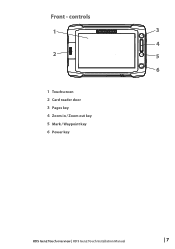
controls 1 3 4 2 5 6 1 Touchscreen 2 Card reader door 3 Pages key 4 Zoom in / Zoom out key 5 Mark / Waypoint key 6 Power key HDS Gen2 Touch overview | HDS Gen2 Touch Installation Manual | 7 Front -
controls 1 3 4 2 5 6 1 Touchscreen 2 Card reader door 3 Pages key 4 Zoom in / Zoom out key 5 Mark / Waypoint key 6 Power key HDS Gen2 Touch overview | HDS Gen2 Touch Installation Manual | 7 Front -
Installation Manual
Page 10
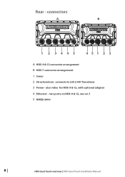
connectors A B 1 2 3445 451 2 3 A HDS-9 & 12 connector arrangement B HDS-7 connector arrangement 1 Sonar 2 StructureScan - connects to LSS-2 HD Transducer 3 Power - two ports on HDS-9 & 12, one on 7 5 NMEA 2000 8 | HDS Gen2 Touch overview | HDS Gen2 Touch Installation Manual Rear - also video for HDS-9 & 12, with optional adaptor 4 Ethernet -
connectors A B 1 2 3445 451 2 3 A HDS-9 & 12 connector arrangement B HDS-7 connector arrangement 1 Sonar 2 StructureScan - connects to LSS-2 HD Transducer 3 Power - two ports on HDS-9 & 12, one on 7 5 NMEA 2000 8 | HDS Gen2 Touch overview | HDS Gen2 Touch Installation Manual Rear - also video for HDS-9 & 12, with optional adaptor 4 Ethernet -
Installation Manual
Page 11
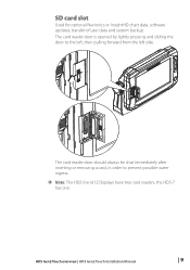
The card reader door should always be shut immediately after inserting or removing a card, in order to the left, then pulling forward from the left side. HDS Gen2 Touch overview | HDS Gen2 Touch Installation Manual | 9 SD card slot Used for optional Navionics or InsightHD chart data, software updates, transfer of user data and system backup. The card reader door is opened by lightly pressing and sliding the door to prevent possible water ingress. ¼¼ Note: The HDS-9 and 12 Displays have two card readers, the HDS-7 has one.
The card reader door should always be shut immediately after inserting or removing a card, in order to the left, then pulling forward from the left side. HDS Gen2 Touch overview | HDS Gen2 Touch Installation Manual | 9 SD card slot Used for optional Navionics or InsightHD chart data, software updates, transfer of user data and system backup. The card reader door is opened by lightly pressing and sliding the door to prevent possible water ingress. ¼¼ Note: The HDS-9 and 12 Displays have two card readers, the HDS-7 has one.
Installation Manual
Page 12
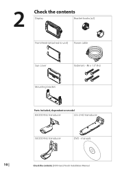
manuals 10 | Check the contents | HDS Gen2 Touch Installation Manual 2 Check the contents Display Bracket knobs (x2) Front Bezel (attached to unit) Power cable Sun cover Fasteners - #6 x 1.5" (4x) Mounting bracket Parts Included, dependent on model 83/200 KHz transducer LSS-2 HD transducer 50/200 KHz transducer DVD -
manuals 10 | Check the contents | HDS Gen2 Touch Installation Manual 2 Check the contents Display Bracket knobs (x2) Front Bezel (attached to unit) Power cable Sun cover Fasteners - #6 x 1.5" (4x) Mounting bracket Parts Included, dependent on model 83/200 KHz transducer LSS-2 HD transducer 50/200 KHz transducer DVD -
Installation Manual
Page 13
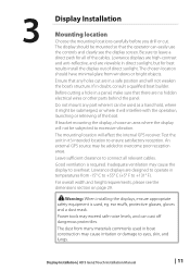
...screen. The chosen location should be added to ensure satisfactory reception. The dust from windows or bright objects. Display Installation | HDS Gen2 Touch Installation Manual | 11 Warning: When installing the displays, ensure appropriate safety equipment is required. Test the unit in it might be ... the mounting locations carefully before you drill or cut are in a safe position and will affect the internal GPS receiver. Lowrance displays are no hidden electrical wires or other parts behind the panel. The display should have minimal glare from many materials ...
...screen. The chosen location should be added to ensure satisfactory reception. The dust from windows or bright objects. Display Installation | HDS Gen2 Touch Installation Manual | 11 Warning: When installing the displays, ensure appropriate safety equipment is required. Test the unit in it might be ... the mounting locations carefully before you drill or cut are in a safe position and will affect the internal GPS receiver. Lowrance displays are no hidden electrical wires or other parts behind the panel. The display should have minimal glare from many materials ...
Installation Manual
Page 14
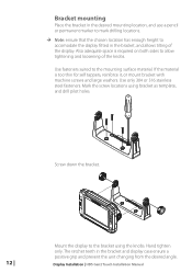
... the display. Also adequate space is too thin for self tappers, reinforce it, or mount bracket with machine screws and large washers. Display Installation | HDS Gen2 Touch Installation Manual Mark the screw locations using the knobs. Screw down the bracket. 12 | Mount the display to the bracket using bracket as template, and drill pilot...
... the display. Also adequate space is too thin for self tappers, reinforce it, or mount bracket with machine screws and large washers. Display Installation | HDS Gen2 Touch Installation Manual Mark the screw locations using the knobs. Screw down the bracket. 12 | Mount the display to the bracket using bracket as template, and drill pilot...
Installation Manual
Page 15
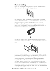
Lastly, fit the bezel with the supplied screws. Once screws are closest to remove any remaining obstructions. Adjust where required. Display Installation | HDS Gen2 Touch Installation Manual | 13 Drill all marked pilot holes, then using an appropriate saw, cut through the template and mounting surface, along the dotted line bordering the shaded ...
Lastly, fit the bezel with the supplied screws. Once screws are closest to remove any remaining obstructions. Adjust where required. Display Installation | HDS Gen2 Touch Installation Manual | 13 Drill all marked pilot holes, then using an appropriate saw, cut through the template and mounting surface, along the dotted line bordering the shaded ...
Installation Manual
Page 16
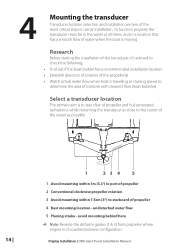
... propeller where engine is moving. Research Before starting the installation of the transducer, it's advised to starboard of propeller 4 Best mounting location - Display Installation | HDS Gen2 Touch Installation Manual 4 Mounting the transducer Transducer location selection and installation are two of the most critical steps in the water at cruising speed to determine the area...
... propeller where engine is moving. Research Before starting the installation of the transducer, it's advised to starboard of propeller 4 Best mounting location - Display Installation | HDS Gen2 Touch Installation Manual 4 Mounting the transducer Transducer location selection and installation are two of the most critical steps in the water at cruising speed to determine the area...
Installation Manual
Page 17
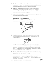
... unit could also lose bottom signal when the boat is not placed in the middle of each outline, to pass the plug through. Display Installation | HDS Gen2 Touch Installation Manual | 15 A good transducer location on these . ¼¼ Note: Boats with strakes or ribs on the hull can create large amounts of turbulence at...
... unit could also lose bottom signal when the boat is not placed in the middle of each outline, to pass the plug through. Display Installation | HDS Gen2 Touch Installation Manual | 15 A good transducer location on these . ¼¼ Note: Boats with strakes or ribs on the hull can create large amounts of turbulence at...
Installation Manual
Page 18
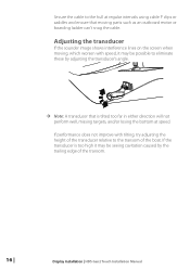
... and ensure that moving , which worsen with tilting, try adjusting the height of the transducer relative to the transom of the transom. 16 | Display Installation | HDS Gen2 Touch Installation Manual
... and ensure that moving , which worsen with tilting, try adjusting the height of the transducer relative to the transom of the transom. 16 | Display Installation | HDS Gen2 Touch Installation Manual
Installation Manual
Page 19
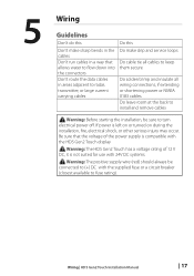
... or NMEA 0183 cables Do leave room at the back to turn electrical power off. Warning: The HDS Gen2 Touch has a voltage rating of the power supply is not suited for use with the HDS Gen2 Touch display ! Wiring | HDS Gen2 Touch Installation Manual | 17 Warning: The positive supply wire (red) should always be sure to install and remove cables...
... or NMEA 0183 cables Do leave room at the back to turn electrical power off. Warning: The HDS Gen2 Touch has a voltage rating of the power supply is not suited for use with the HDS Gen2 Touch display ! Wiring | HDS Gen2 Touch Installation Manual | 17 Warning: The positive supply wire (red) should always be sure to install and remove cables...
Installation Manual
Page 20
... up line may be used to control the power state of the supplied power cable has two discrete cables exiting from it. Wiring | HDS Gen2 Touch Installation Manual This means that the modules are turned on the moment the display is powered up. ¼¼ Note: Broadband radar will be put... in standby, when triggered by a 12 V DC system. They are protected against reverse polarity, under voltage and over voltage. Power connection HDS Gen2 Touch displays are ...
... up line may be used to control the power state of the supplied power cable has two discrete cables exiting from it. Wiring | HDS Gen2 Touch Installation Manual This means that the modules are turned on the moment the display is powered up. ¼¼ Note: Broadband radar will be put... in standby, when triggered by a 12 V DC system. They are protected against reverse polarity, under voltage and over voltage. Power connection HDS Gen2 Touch displays are ...
Installation Manual
Page 21
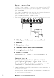
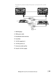
The following demonstrates the power connections for a small system. 1 2 3 7 1 HDS Displays 2 HDS power cable 3 Broadband radar interface 4 SonicHub 5 12 V DC negative (-) 6 12 V DC postive (+) 7 Accessory wake up line 8 Vessel's 12 V DC supply 4 5 6 +_ 8 Wiring | HDS Gen2 Touch Installation Manual | 19
The following demonstrates the power connections for a small system. 1 2 3 7 1 HDS Displays 2 HDS power cable 3 Broadband radar interface 4 SonicHub 5 12 V DC negative (-) 6 12 V DC postive (+) 7 Accessory wake up line 8 Vessel's 12 V DC supply 4 5 6 +_ 8 Wiring | HDS Gen2 Touch Installation Manual | 19
Installation Manual
Page 22
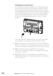
... collar to the Overview section of an adaptor cable - see page 30. 20 | Wiring | HDS Gen2 Touch Installation Manual Refer to secure. ¼¼ Note: Connectors are not in same location on the HDS-7 display as they are on all units. ¼¼ Note: Sonar data can be plugged ...in one orientation. Transducer connection All Combo HDS Gen2 Touch displays have internal Broadband and StructureScan sonar (...
... collar to the Overview section of an adaptor cable - see page 30. 20 | Wiring | HDS Gen2 Touch Installation Manual Refer to secure. ¼¼ Note: Connectors are not in same location on the HDS-7 display as they are on all units. ¼¼ Note: Sonar data can be plugged ...in one orientation. Transducer connection All Combo HDS Gen2 Touch displays have internal Broadband and StructureScan sonar (...

Installation Manual
Page 23
Navico ethernet cables have two. The NEP-2 modules are fitted with 5 ethernet ports. Wiring | HDS Gen2 Touch Installation Manual | 21 Connecting to multiple devices If connecting more NEP-2 modules together to provide the required ports. See page 31 for cable options. &#...NEP-2). Connecting directly to a single device The ethernet port is auto sensing, meaning that the unit can connect to one ethernet port, whereas the HDS-9 and 12 displays have a locking collar, for maintaining a reliable, waterproof connection. Ethernet device connection Ethernet is possible to link two or more than...
Navico ethernet cables have two. The NEP-2 modules are fitted with 5 ethernet ports. Wiring | HDS Gen2 Touch Installation Manual | 21 Connecting to multiple devices If connecting more NEP-2 modules together to provide the required ports. See page 31 for cable options. &#...NEP-2). Connecting directly to a single device The ethernet port is auto sensing, meaning that the unit can connect to one ethernet port, whereas the HDS-9 and 12 displays have a locking collar, for maintaining a reliable, waterproof connection. Ethernet device connection Ethernet is possible to link two or more than...

