StructureMap Guide
Page 3
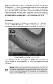
... a StructureMap in saved mode water. Typically it will show up behind the vessel icon. Saved mode is used when revisiting an area that have Structurescan installed on or off , all recent sonar history is turned off of the underwater environment that will display the last 4-5 minutes of the lake and how...
... a StructureMap in saved mode water. Typically it will show up behind the vessel icon. Saved mode is used when revisiting an area that have Structurescan installed on or off , all recent sonar history is turned off of the underwater environment that will display the last 4-5 minutes of the lake and how...

Installation Manual
Page 1
HDS Series Installation manual
HDS Series Installation manual
Installation Manual
Page 2
... make changes to the product at the time of the Documentation. It is a valuable resource for observing safe boating practices. www.lowrance.com 1 Please contact your nearest distributor if you Your feedback is important and helps Navico ensure that will be translated to specifications without...product as a separate document. • It is shipped with the product registration card. • In case of any queries, refer to install and use the instrument and transducers in this version of this manual to the following address: [email protected] Warranty • The warranty...
... make changes to the product at the time of the Documentation. It is a valuable resource for observing safe boating practices. www.lowrance.com 1 Please contact your nearest distributor if you Your feedback is important and helps Navico ensure that will be translated to specifications without...product as a separate document. • It is shipped with the product registration card. • In case of any queries, refer to install and use the instrument and transducers in this version of this manual to the following address: [email protected] Warranty • The warranty...

Installation Manual
Page 4
... 5 About this Manual...5 Important Safety and Warning Information 5 Check the Parts...6 Overview...7 Display Installation 9 Mounting location...9 Panel Mount...11 Bracket Mount...12 Transducer Installation 14 Recommended Tools and Supplies 14 Skimmer Installation Instructions 15 System Architecture 28 Wiring the HDS 29 Wiring Guidelines...29 Power/Data Cable...30 NMEA 0183 Wiring Table 31 NMEA...
... 5 About this Manual...5 Important Safety and Warning Information 5 Check the Parts...6 Overview...7 Display Installation 9 Mounting location...9 Panel Mount...11 Bracket Mount...12 Transducer Installation 14 Recommended Tools and Supplies 14 Skimmer Installation Instructions 15 System Architecture 28 Wiring the HDS 29 Wiring Guidelines...29 Power/Data Cable...30 NMEA 0183 Wiring Table 31 NMEA...
Installation Manual
Page 6
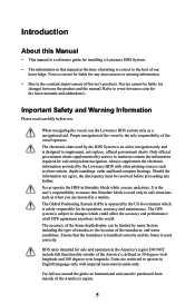
... observations, depth soundings, radar and hand compass bearings. Introduction About this Manual • This manual is a reference guide for installing a Lowrance HDS System. • The information in this manual at the time of printing is correct to supplement, not replace, official government charts...location of the America's, defined as 30 degrees west longitude and 180 degrees west longitude. HDS units intended for sale and operation in a marina. The electronic chart used by the Lowrance HDS with imperial (non-metric) units only. Navico can be purchased from outside of the ...
... observations, depth soundings, radar and hand compass bearings. Introduction About this Manual • This manual is a reference guide for installing a Lowrance HDS System. • The information in this manual at the time of printing is correct to supplement, not replace, official government charts...location of the America's, defined as 30 degrees west longitude and 180 degrees west longitude. HDS units intended for sale and operation in a marina. The electronic chart used by the Lowrance HDS with imperial (non-metric) units only. Navico can be purchased from outside of the ...

Installation Manual
Page 7
Check the Parts HDS Head Unit Models: 5", 7", 8" or 10" Packaged Parts List ISO 30 Degree with Perspective HDS Bezel HDS Dust Cover HDS Mounting Bracket HDS Cut-out Template HDS Power/Data Cable HDS Installation Manual HDS Quick start guide HDS 4 x SCREW #10 3/4 PAN HEAD SS SELFTAP HDS Bracket Knobs HDS Connector Caps HDS Operation Manual HDS 4 x SCREW NO. 6X1.5 PANHEAD PHILLIPS TP1 6
Check the Parts HDS Head Unit Models: 5", 7", 8" or 10" Packaged Parts List ISO 30 Degree with Perspective HDS Bezel HDS Dust Cover HDS Mounting Bracket HDS Cut-out Template HDS Power/Data Cable HDS Installation Manual HDS Quick start guide HDS 4 x SCREW #10 3/4 PAN HEAD SS SELFTAP HDS Bracket Knobs HDS Connector Caps HDS Operation Manual HDS 4 x SCREW NO. 6X1.5 PANHEAD PHILLIPS TP1 6
Installation Manual
Page 10
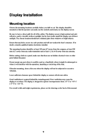
..., and is viewable in a panel, make sure that any antenna. Ensure that there are in doubt, consult a qualified marine electronics installer. Before cutting a hole in direct sunlight, but for all relevant cables. For overall width and height requirements, please see the display screen. Display...The chosen location should have minimal glare from any holes cut . Poor ventilation may cause the display to leave a direct path for best results install the display out of this manual. 9 If in a safe position and will not weaken the boat's structure. The mounting location should be ...
..., and is viewable in a panel, make sure that any antenna. Ensure that there are in doubt, consult a qualified marine electronics installer. Before cutting a hole in direct sunlight, but for all relevant cables. For overall width and height requirements, please see the display screen. Display...The chosen location should have minimal glare from any holes cut . Poor ventilation may cause the display to leave a direct path for best results install the display out of this manual. 9 If in a safe position and will not weaken the boat's structure. The mounting location should be ...
Installation Manual
Page 12
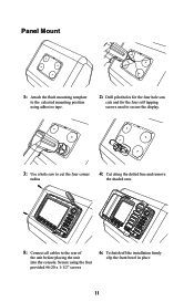
Secure using adhesive tape. 2: Drill pilot holes for the four hole saw cuts and for the four self tapping screws used to secure the display. 3: Use a hole saw to cut the four corner radius 4: Cut along the dotted line and remove the shaded area. 5: Connect all cables to the selected mounting position using the four provided #6-20 x 1-1/2" screws 6: To finish off the installation firmly clip the front bezel in place 11 Panel Mount 1: Attach the flush mounting template to the rear of the unit before placing the unit into the console.
Secure using adhesive tape. 2: Drill pilot holes for the four hole saw cuts and for the four self tapping screws used to secure the display. 3: Use a hole saw to cut the four corner radius 4: Cut along the dotted line and remove the shaded area. 5: Connect all cables to the selected mounting position using the four provided #6-20 x 1-1/2" screws 6: To finish off the installation firmly clip the front bezel in place 11 Panel Mount 1: Attach the flush mounting template to the rear of the unit before placing the unit into the console.
Installation Manual
Page 15
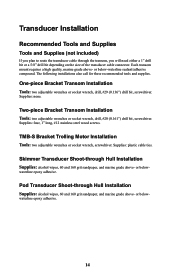
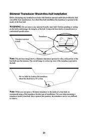
...drill bit, screwdriver. Supplies: plastic cable ties. waterline epoxy adhesive. or below - or below-waterline sealant/adhesive compound. One-piece Bracket Transom Installation Tools: two adjustable wrenches or socket wrench, drill, #29 (0.136") drill bit, screwdriver. Supplies: none. Skimmer Transducer Shoot-through the ...or a 5/8" drill bit depending on the size of the transducer cable connector. waterline epoxy adhesive. 14 Transducer Installation Recommended Tools and Supplies Tools and Supplies (not included) If you plan to route the transducer cable through Hull...
...drill bit, screwdriver. Supplies: plastic cable ties. waterline epoxy adhesive. or below - or below-waterline sealant/adhesive compound. One-piece Bracket Transom Installation Tools: two adjustable wrenches or socket wrench, drill, #29 (0.136") drill bit, screwdriver. Supplies: none. Skimmer Transducer Shoot-through the ...or a 5/8" drill bit depending on the size of the transducer cable connector. waterline epoxy adhesive. 14 Transducer Installation Recommended Tools and Supplies Tools and Supplies (not included) If you plan to route the transducer cable through Hull...
Installation Manual
Page 16
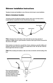
... sure it does not interfere with strakes or ribs on these types of boats is between the ribs closest to the engine. Skimmer Installation Instructions Transducer location and installation is one foot from the prop. 15 If the transducer is on -screen in a location that has a smooth flow of the boat. The... unit also could lose bottom signal when the boat is not placed in sonar installation. Select a transducer location To function properly the Skimmer transducer must be in the water at higher speeds.
... sure it does not interfere with strakes or ribs on these types of boats is between the ribs closest to the engine. Skimmer Installation Instructions Transducer location and installation is one foot from the prop. 15 If the transducer is on -screen in a location that has a smooth flow of the boat. The... unit also could lose bottom signal when the boat is not placed in sonar installation. Select a transducer location To function properly the Skimmer transducer must be in the water at higher speeds.

Installation Manual
Page 23
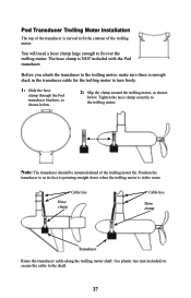
...The TMB-S bracket is used to attach a one -piece bracket transducers only. If you may consider using a Pod transducer for trolling motor installation. Use plastic ties (not included) to secure the cable to the trolling motor. Position the transducer so its "face" is pointing straight... down when the trolling motor is in the water. TMB-S Trolling Motor Bracket Installation Note: The TMB-S bracket is designed for one -piece bracket transducer to a trolling motor. Adjustable strap Route the transducer cable along ...
...The TMB-S bracket is used to attach a one -piece bracket transducers only. If you may consider using a Pod transducer for trolling motor installation. Use plastic ties (not included) to secure the cable to the trolling motor. Position the transducer so its "face" is pointing straight... down when the trolling motor is in the water. TMB-S Trolling Motor Bracket Installation Note: The TMB-S bracket is designed for one -piece bracket transducer to a trolling motor. Adjustable strap Route the transducer cable along ...
Installation Manual
Page 24
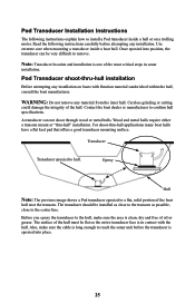
The circled image is epoxied to a flat, solid portion of the hull. WARNING: Do not remove any installation on the hull could damage the integrity of the boat hull near the transom. Transducer epoxied to place the transducer where the dead ...rise is 10° or less. Skimmer Transducer Shoot-thru-hull Installation Before attempting any material from the inner hull. In a shoot-thru-hull installation the transducer is a close-up view of installation. Careless grinding or cutting on boats with flotation material sandwiched within the hull, consult the...
The circled image is epoxied to a flat, solid portion of the hull. WARNING: Do not remove any installation on the hull could damage the integrity of the boat hull near the transom. Transducer epoxied to place the transducer where the dead ...rise is 10° or less. Skimmer Transducer Shoot-thru-hull Installation Before attempting any material from the inner hull. In a shoot-thru-hull installation the transducer is a close-up view of installation. Careless grinding or cutting on boats with flotation material sandwiched within the hull, consult the...
Installation Manual
Page 25
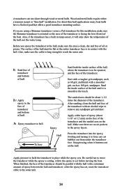
... Hull Sand both the inside surface of the hull, not the water temp. Make sure there are using a Skimmer transducer versus a Pod transducer for this installation, make sure the Skimmer transducer is oriented so the nose of the transducer. Apply pressure to move the transducer while the epoxy is in temp... mounting surface. The sanded area should be about 1-16" or 1.5 mm) on the hull. Wood and metal hulls require either a transom mount or "thru-hull" installation.
... Hull Sand both the inside surface of the hull, not the water temp. Make sure there are using a Skimmer transducer versus a Pod transducer for this installation, make sure the Skimmer transducer is oriented so the nose of the transducer. Apply pressure to move the transducer while the epoxy is in temp... mounting surface. The sanded area should be about 1-16" or 1.5 mm) on the hull. Wood and metal hulls require either a transom mount or "thru-hull" installation.
Installation Manual
Page 26
... boat manufacturer. A transducer can be very difficult to remove. The transducer should be flat so the entire transducer face is in sonar installation. Before you epoxy the transducer to the center line. Contact the boat dealer or manufacturer to a flat, solid portion of oil or... sonar unit before attempting any material from the inner hull. Once epoxied into place. 25 WARNING: Do not remove any installation. Note: Transducer location and installation is one of the hull. For shoot-thru-hull applications many boat hulls have a flat keel pad that offers a ...
... boat manufacturer. A transducer can be very difficult to remove. The transducer should be flat so the entire transducer face is in sonar installation. Before you epoxy the transducer to the center line. Contact the boat dealer or manufacturer to a flat, solid portion of oil or... sonar unit before attempting any material from the inner hull. Once epoxied into place. 25 WARNING: Do not remove any installation. Note: Transducer location and installation is one of the hull. For shoot-thru-hull applications many boat hulls have a flat keel pad that offers a ...
Installation Manual
Page 28
Pod Transducer Trolling Motor Installation The top of the transducer is curved to fit the contour of the trolling motor fin. You will need a hose clamp large enough to the ...
Pod Transducer Trolling Motor Installation The top of the transducer is curved to fit the contour of the trolling motor fin. You will need a hose clamp large enough to the ...
Installation Manual
Page 30
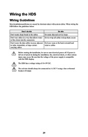
The HDS has a voltage rating of the power supply is left on or turned on during the installation, fire, electrical shock, or other serious injury may occur. Be sure that... data cables in areas adjacent Do leave room at the back to install and to radar, transmitter, or large current remove cables carrying cables Before starting the installation, be connected to turn electrical power off. Don't do this Do...or thermal breaker (10 Amp) 29 If power is compatible with system cables. Wiring the HDS Wiring Guidelines Most installation problems are caused by shortcuts taken with the...
The HDS has a voltage rating of the power supply is left on or turned on during the installation, fire, electrical shock, or other serious injury may occur. Be sure that... data cables in areas adjacent Do leave room at the back to install and to radar, transmitter, or large current remove cables carrying cables Before starting the installation, be connected to turn electrical power off. Don't do this Do...or thermal breaker (10 Amp) 29 If power is compatible with system cables. Wiring the HDS Wiring Guidelines Most installation problems are caused by shortcuts taken with the...
Installation Manual
Page 38
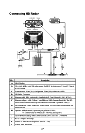
... ONLY Scanner D Ethernet HEADING In A B C D F E G J H I AT10HD Fast heading NMEA2000 to NMEA0183 converter. (24006694) J RC42 Compass (Heading) K SimNet to HDS or via a Network Expansion Port (H). G HDS and Radar Power. See radar installation manual for HDS. B LRA1800 &LRA2400 HD radar system for radar fuse size H Optional NEP (Network Expansion port) (000-0132-031) For Chart overlay or...
... ONLY Scanner D Ethernet HEADING In A B C D F E G J H I AT10HD Fast heading NMEA2000 to NMEA0183 converter. (24006694) J RC42 Compass (Heading) K SimNet to HDS or via a Network Expansion Port (H). G HDS and Radar Power. See radar installation manual for HDS. B LRA1800 &LRA2400 HD radar system for radar fuse size H Optional NEP (Network Expansion port) (000-0132-031) For Chart overlay or...

Installation Manual
Page 40
...of the drop down list. Sonar Setup To ensure proper sonar operation you could use data from a network data source or data from the sonar installation menu. To do not want to use different ping speeds, bottom search ranges and color pallets to properly work with your transducer. The default ...language is set the HDS to use your type of the minimum settings we recommend you operate in . If, for the depth of water you set itself via the ...
...of the drop down list. Sonar Setup To ensure proper sonar operation you could use data from a network data source or data from the sonar installation menu. To do not want to use different ping speeds, bottom search ranges and color pallets to properly work with your transducer. The default ...language is set the HDS to use your type of the minimum settings we recommend you operate in . If, for the depth of water you set itself via the ...
Installation Manual
Page 42
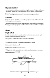
... strength of satellites within range of navigation information. B: Depth Below Transducer: no offset required. A B C 41 The depth offset can be found via Menu, Settings, Sonar, Installation. A: Depth below the surface. C: Depth Below Surface (waterline) value: Is the distance from transducer to the keel. Enter a negative value. Satellites Monitors the location of...
... strength of satellites within range of navigation information. B: Depth Below Transducer: no offset required. A B C 41 The depth offset can be found via Menu, Settings, Sonar, Installation. A: Depth below the surface. C: Depth Below Surface (waterline) value: Is the distance from transducer to the keel. Enter a negative value. Satellites Monitors the location of...
HDS Gen2 2.5 software release addendum - EN
Page 10
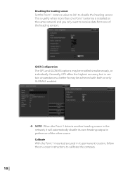
... own heading output in its permanent location, follow the on the same network and you only want to receive data from one Point 1 antenna is installed on -screen instructions to disable the heading sensor. Calibrate With the Point 1 mounted securely in preference of the heading sensors. GNSS Configuration The GPS and...
... own heading output in its permanent location, follow the on the same network and you only want to receive data from one Point 1 antenna is installed on -screen instructions to disable the heading sensor. Calibrate With the Point 1 mounted securely in preference of the heading sensors. GNSS Configuration The GPS and...


