
Installation Guide
Page 3
...instruction manuals, user guides and other information relating to the product (Documentation) may not be translated to, or has been translated from, another language (Translation). Warranty The warranty card is supplied as at any further assistance. Compliance statements This equipment complies with: • CE under 2014/53/EU Directive Preface | HDS Carbon Installation Manual 3 It is the owner...'s sole responsibility to install and use the equipment in this version of the manual. The user of the Documentation....
...instruction manuals, user guides and other information relating to the product (Documentation) may not be translated to, or has been translated from, another language (Translation). Warranty The warranty card is supplied as at any further assistance. Compliance statements This equipment complies with: • CE under 2014/53/EU Directive Preface | HDS Carbon Installation Manual 3 It is the owner...'s sole responsibility to install and use the equipment in this version of the manual. The user of the Documentation....

Installation Guide
Page 9
... Check the contents 11 HDS Carbon box contents 12 Overview 12 The front panel and keys 14 Rear connections 14 Card reader 16 Installation 16 Mounting location 17 Viewing angle 17 Bracket mounting 19 Panel mounting 20 Mounting the transducer 20 Research 20 Select a transducer location 21 Attaching the transducer 22 Adjusting the transducer 24 Wiring 24 Guidelines 25 Power connection 26 Transducer connection 27 Ethernet connector...
... Check the contents 11 HDS Carbon box contents 12 Overview 12 The front panel and keys 14 Rear connections 14 Card reader 16 Installation 16 Mounting location 17 Viewing angle 17 Bracket mounting 19 Panel mounting 20 Mounting the transducer 20 Research 20 Select a transducer location 21 Attaching the transducer 22 Adjusting the transducer 24 Wiring 24 Guidelines 25 Power connection 26 Transducer connection 27 Ethernet connector...

Installation Guide
Page 10
... 69 Mercury® 69 Suzuki Marine® 69 Software updates and data backup 73 Dimensional drawings 73 HDS 7 Carbon 73 HDS 9 Carbon 74 HDS 12 Carbon 75 Accessories 75 NMEA 2000 75 Display accessories 76 Ethernet cables 76 Other accessories 76 Sonar accessories 78 Supported data 78 NMEA 2000 compliant PGN List 81 NMEA 0183 supported sentences 83 Technical specifications 83 HDS Carbon technical specifications 10 Contents | HDS Carbon Installation Manual
... 69 Mercury® 69 Suzuki Marine® 69 Software updates and data backup 73 Dimensional drawings 73 HDS 7 Carbon 73 HDS 9 Carbon 74 HDS 12 Carbon 75 Accessories 75 NMEA 2000 75 Display accessories 76 Ethernet cables 76 Other accessories 76 Sonar accessories 78 Supported data 78 NMEA 2000 compliant PGN List 81 NMEA 0183 supported sentences 83 Technical specifications 83 HDS Carbon technical specifications 10 Contents | HDS Carbon Installation Manual

Installation Guide
Page 16
.... Do not mount any holes cut . 3 Installation Mounting location Choose the mounting locations carefully before you drill or cut are no hidden electrical wires or other parts behind the panel. The unit has a high-contrast screen and is possible to route cables to connect all relevant cables. Ensure that it may affect the internal GPS receiver. The mounting location may be...
.... Do not mount any holes cut . 3 Installation Mounting location Choose the mounting locations carefully before you drill or cut are no hidden electrical wires or other parts behind the panel. The unit has a high-contrast screen and is possible to route cables to connect all relevant cables. Ensure that it may affect the internal GPS receiver. The mounting location may be...

Installation Guide
Page 24
... and unplugging of the power supply is left on or turned on all cables to keep them secure • solder/crimp and insulate all wiring connections if extending or shortening the cables. 5 Wiring Guidelines Don't: • make drip and service loops • use with 24 V DC systems. Warning: The positive supply wire (red) should be sure to fuse rating). 24 Wiring | HDS Carbon Installation Manual
... and unplugging of the power supply is left on or turned on all cables to keep them secure • solder/crimp and insulate all wiring connections if extending or shortening the cables. 5 Wiring Guidelines Don't: • make drip and service loops • use with 24 V DC systems. Warning: The positive supply wire (red) should be sure to fuse rating). 24 Wiring | HDS Carbon Installation Manual

Installation Guide
Page 25
... be used to a single termination point. Wiring | HDS Carbon Installation Manual 25 Power connection The plug of modules such as SonicHub, StructureScan, and Broadband radar. For connection, simply combine all yellow wires on for certain Navico expansion modules (Yellow wire) 4 1 6 23 _+ 5 1 Power cable 2 12 V negative wire (black) 3 Accessory Wake Up wire (yellow) 4 12 V positive wire (red) shown with fuse holder installed inline 5 Vessel's 12 V DC supply 6 NMEA 0183 cable Accessory...
... be used to a single termination point. Wiring | HDS Carbon Installation Manual 25 Power connection The plug of modules such as SonicHub, StructureScan, and Broadband radar. For connection, simply combine all yellow wires on for certain Navico expansion modules (Yellow wire) 4 1 6 23 _+ 5 1 Power cable 2 12 V negative wire (black) 3 Accessory Wake Up wire (yellow) 4 12 V positive wire (red) shown with fuse holder installed inline 5 Vessel's 12 V DC supply 6 NMEA 0183 cable Accessory...

Installation Guide
Page 26
... Sonar. The following demonstrates the power connections for a typical small system. POWER A 1 POWER B 2 3 4 5 6 +_ 7 A Power connection to unit on the left B Power connection to unit on page 14. 26 Wiring | HDS Carbon Installation Manual For connector location, refer to the embossed labeling on the unit or the section "Rear connections" on the right 1 Power cable connectors to the socket labelled Structure. SonicHub2) 4 12 V DC negative (-) 5 12...
... Sonar. The following demonstrates the power connections for a typical small system. POWER A 1 POWER B 2 3 4 5 6 +_ 7 A Power connection to unit on the left B Power connection to unit on page 14. 26 Wiring | HDS Carbon Installation Manual For connector location, refer to the embossed labeling on the unit or the section "Rear connections" on the right 1 Power cable connectors to the socket labelled Structure. SonicHub2) 4 12 V DC negative (-) 5 12...

Installation Guide
Page 29
...an existing NMEA 2000 network that already has its own 12 V DC power supply protected by 24 V DC. Ú Note: Do not connect the NMEA 2000 power cable to the same terminals as the engine start batteries, autopilot computer, bow thruster or other high current devices...A NMEA 2000 network, using Micro-C cabling, has a maximum cable length of the backbone. Connect power at each end of 100 m (328 ft), between any location in the network, and ensure the existing network is made up of 6 m (20 ft). Wiring | HDS Carbon Installation Manual 29 Micro-C being the more commonly used size. • ...
...an existing NMEA 2000 network that already has its own 12 V DC power supply protected by 24 V DC. Ú Note: Do not connect the NMEA 2000 power cable to the same terminals as the engine start batteries, autopilot computer, bow thruster or other high current devices...A NMEA 2000 network, using Micro-C cabling, has a maximum cable length of the backbone. Connect power at each end of 100 m (328 ft), between any location in the network, and ensure the existing network is made up of 6 m (20 ft). Wiring | HDS Carbon Installation Manual 29 Micro-C being the more commonly used size. • ...

Installation Guide
Page 52
...cable steer only)* Probable cause: The clutch in Helm-1. • Check the Helm-1 drive motor. Recommended action: • Disconnect the Helm-1 and verify that the alarm disappears. • Check resistance of 20 deg. (Automatic reset when inside limit). • The boat speed is too low. • The response setting...too much current. Recommended action: 52 Software Setup | HDS Carbon Installation Manual • Check cable and connector. • Check the alignment as per the installation instructions. No rudder response (For Helm-1/cable steer only)* Probable cause: No response to...
...cable steer only)* Probable cause: The clutch in Helm-1. • Check the Helm-1 drive motor. Recommended action: • Disconnect the Helm-1 and verify that the alarm disappears. • Check resistance of 20 deg. (Automatic reset when inside limit). • The boat speed is too low. • The response setting...too much current. Recommended action: 52 Software Setup | HDS Carbon Installation Manual • Check cable and connector. • Check the alignment as per the installation instructions. No rudder response (For Helm-1/cable steer only)* Probable cause: No response to...
Installation Guide
Page 56
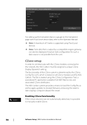
... module firmware, removing the need to manually enable CZone. 56 Software Setup | HDS Carbon Installation Manual The file is stored on the Instrument page with the CZone modules connected to the network, the HDS Carbon must be displayed, however tank configuration for such a data source is possible to take a laptop computer aboard the vessel. The functionality of 5 tanks is supported using...
... module firmware, removing the need to manually enable CZone. 56 Software Setup | HDS Carbon Installation Manual The file is stored on the Instrument page with the CZone modules connected to the network, the HDS Carbon must be displayed, however tank configuration for such a data source is possible to take a laptop computer aboard the vessel. The functionality of 5 tanks is supported using...

Installation Guide
Page 63
...Setup | HDS Carbon Installation Manual 63 The unit displays a prompt similar to the following this , select the Wireless devices page in the Device Name setting. If more than one -time connection, or Always if device is reflected on the smartphone. If the unit does not appear, follow the on screen instructions to manually... if required. Ú Note: The internal wireless module only supports GoFree connection to the unit. 4. Enter the Network Key in range, review the Wireless devices page from the unit's Wireless settings dialog to Access Point mode. Select the graphic icon of the unit.
...Setup | HDS Carbon Installation Manual 63 The unit displays a prompt similar to the following this , select the Wireless devices page in the Device Name setting. If more than one -time connection, or Always if device is reflected on the smartphone. If the unit does not appear, follow the on screen instructions to manually... if required. Ú Note: The internal wireless module only supports GoFree connection to the unit. 4. Enter the Network Key in range, review the Wireless devices page from the unit's Wireless settings dialog to Access Point mode. Select the graphic icon of the unit.
Installation Guide
Page 75
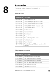
...-11047-001 Point-1 high speed GPS antenna with built-in compass Display accessories Part Number Description 000-11010-001 HDS Carbon video adapter cable 000-13978-001 HDS 7 Carbon bezel and card door 000-13979-001 HDS 9 Carbon bezel and card door 000-13980-001 HDS 12 Carbon bezel and card door 000-12242-001 HDS 7 Carbon suncover 000-12244-001 HDS 9 Carbon suncover Accessories | HDS Carbon Installation Manual 75
...-11047-001 Point-1 high speed GPS antenna with built-in compass Display accessories Part Number Description 000-11010-001 HDS Carbon video adapter cable 000-13978-001 HDS 7 Carbon bezel and card door 000-13979-001 HDS 9 Carbon bezel and card door 000-13980-001 HDS 12 Carbon bezel and card door 000-12242-001 HDS 7 Carbon suncover 000-12244-001 HDS 9 Carbon suncover Accessories | HDS Carbon Installation Manual 75
Installation Guide
Page 76
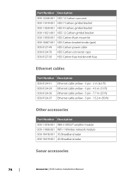
... 000-12246-001 HDS 12 Carbon suncover 000-11019-001 HDS 7 Carbon gimbal bracket 000-11020-001 HDS 9 Carbon gimbal bracket 000-11021-001 HDS 12 Carbon gimbal bracket 000-11050-001 HDS Carbon flush mount kit 000-10467-001 HDS Carbon bracket knobs (pair) 000-0127-49 HDS Carbon power cable 000-0124-70 HDS Carbon connector caps 000-0127-50 HDS Carbon fuse holder with fuse Ethernet cables Part Number Description 000-0124-51 000-0124-29 000-0124...
... 000-12246-001 HDS 12 Carbon suncover 000-11019-001 HDS 7 Carbon gimbal bracket 000-11020-001 HDS 9 Carbon gimbal bracket 000-11021-001 HDS 12 Carbon gimbal bracket 000-11050-001 HDS Carbon flush mount kit 000-10467-001 HDS Carbon bracket knobs (pair) 000-0127-49 HDS Carbon power cable 000-0124-70 HDS Carbon connector caps 000-0127-50 HDS Carbon fuse holder with fuse Ethernet cables Part Number Description 000-0124-51 000-0124-29 000-0124...
Installation Guide
Page 85
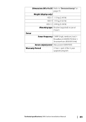
Dimensions (W x H x D) Refer to "Dimensional drawings" on page 73 Weight (display only) HDS-7 1.13 kg (2.49 lb) HDS-9 1.55 kg (3.42 lb) HDS-12 2.44 kg (5.38 lb) Mounting type Bracket (supplied) or panel mount Sonar Sonar frequency CHIRP (high, medium, low) + Broadband (200/83/50 kHz) + StructureScan (800/455 kHz) Sonar output power Max power 500W RMS Warranty Period 2 Year + part of the 5 year upgrade program Technical specifications| HDS Carbon Installation Manual 85
Dimensions (W x H x D) Refer to "Dimensional drawings" on page 73 Weight (display only) HDS-7 1.13 kg (2.49 lb) HDS-9 1.55 kg (3.42 lb) HDS-12 2.44 kg (5.38 lb) Mounting type Bracket (supplied) or panel mount Sonar Sonar frequency CHIRP (high, medium, low) + Broadband (200/83/50 kHz) + StructureScan (800/455 kHz) Sonar output power Max power 500W RMS Warranty Period 2 Year + part of the 5 year upgrade program Technical specifications| HDS Carbon Installation Manual 85

Operators Manual EN
Page 22
...Power-Poles, you are pairing dual Power-Poles, also review "Pairing with dual Power-Poles" on page 99. Select it to "Info panels" on page 127. 22 Introduction | HDS Carbon Operator Manual If you pair the Power-Poles with BEP's CZone system used for more information, refer to display the Power-Pole controller. BEP CZone integration The HDS Carbon integrates with the HDS Carbon using... panels. Refer to this documentation and to the HDS Carbon Installation manual for how to "Audio" on page 153 for controlling and monitoring a distributed power system on the type of the gauges. You ...
...Power-Poles, you are pairing dual Power-Poles, also review "Pairing with dual Power-Poles" on page 99. Select it to "Info panels" on page 127. 22 Introduction | HDS Carbon Operator Manual If you pair the Power-Poles with BEP's CZone system used for more information, refer to display the Power-Pole controller. BEP CZone integration The HDS Carbon integrates with the HDS Carbon using... panels. Refer to this documentation and to the HDS Carbon Installation manual for how to "Audio" on page 153 for controlling and monitoring a distributed power system on the type of the gauges. You ...

Operators Manual EN
Page 68
The Sonar image 1 Fish arches 2 History preview* 3 Temperature graph* 4 Depth at cursor 5 Amplitude scope* 6 Zoom (range) buttons 7 Water depth and Water temperature at cursor location 8 Range scale 9 Bottom * Optional Sonar items. Ú Note: You turn the optional Sonar items on page 76. 68 Sonar | HDS Carbon Operator Manual 7 Sonar The Sonar function provides a view of the bottom. Refer to detect fish and examine the structure of the water and bottom beneath your vessel, allowing you to "view options" on /off individually.
The Sonar image 1 Fish arches 2 History preview* 3 Temperature graph* 4 Depth at cursor 5 Amplitude scope* 6 Zoom (range) buttons 7 Water depth and Water temperature at cursor location 8 Range scale 9 Bottom * Optional Sonar items. Ú Note: You turn the optional Sonar items on page 76. 68 Sonar | HDS Carbon Operator Manual 7 Sonar The Sonar function provides a view of the bottom. Refer to detect fish and examine the structure of the water and bottom beneath your vessel, allowing you to "view options" on /off individually.
Operators Manual EN
Page 70
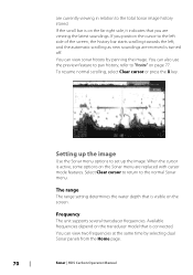
... sonar history by selecting dual Sonar panels from the Home page. 70 Sonar | HDS Carbon Operator Manual To resume normal scrolling, select Clear cursor or press the X key. The range The range setting determines the water depth that you position the cursor to the left side of the screen..."Preview" on the screen. Frequency The unit supports several transducer frequencies. Setting up the image Use the Sonar menu options to the normal Sonar menu. You can view two frequencies at the same time by panning the image. Available frequencies depend on the transducer model that is active, ...
... sonar history by selecting dual Sonar panels from the Home page. 70 Sonar | HDS Carbon Operator Manual To resume normal scrolling, select Clear cursor or press the X key. The range The range setting determines the water depth that you position the cursor to the left side of the screen..."Preview" on the screen. Frequency The unit supports several transducer frequencies. Setting up the image Use the Sonar menu options to the normal Sonar menu. You can view two frequencies at the same time by panning the image. Available frequencies depend on the transducer model that is active, ...

Operators Manual EN
Page 88
... SpotlightScan | HDS Carbon Operator Manual The SpotlightScan feature can be mounted on your trolling motor. For installation instructions, refer to fish them. Its trolling motor position sensor ensures that the SpotlightScan returns match up correctly with the orientation of your trolling motor and its trolling motor position sensor mounted on the trolling motor foot pedal. The SpotlightScan transducer can...
... SpotlightScan | HDS Carbon Operator Manual The SpotlightScan feature can be mounted on your trolling motor. For installation instructions, refer to fish them. Its trolling motor position sensor ensures that the SpotlightScan returns match up correctly with the orientation of your trolling motor and its trolling motor position sensor mounted on the trolling motor foot pedal. The SpotlightScan transducer can...

Operators Manual EN
Page 128
... connect without needing a password each time. To view and change modes. Selecting the internal wireless or a WIFI-1 device provides additional detail. Client settings Displays information about the ...wireless hotspot your unit was connected to disconnect devices that you to . To select a network (hotspot) to connect to a wireless hotspot. Selecting Always allow means the device can use to connect the wireless functionality to , the internal wireless must be in Client Mode. You can Wireless connection | HDS Carbon Operator Manual...
... connect without needing a password each time. To view and change modes. Selecting the internal wireless or a WIFI-1 device provides additional detail. Client settings Displays information about the ...wireless hotspot your unit was connected to disconnect devices that you to . To select a network (hotspot) to connect to a wireless hotspot. Selecting Always allow means the device can use to connect the wireless functionality to , the internal wireless must be in Client Mode. You can Wireless connection | HDS Carbon Operator Manual...

Quick Start Guide EN
Page 6
Select Clear Cursor or press the Exit key to activate the cursor. EN Multi-touch zooming 6 | HDS Carbon | Quick Start Guide - Saving a Man Overboard (MOB) waypoint Using the cursor Tap the screen or press the Cursor keys to remove the cursor from the page. Drag your finger in any direction to pan the screen.
Select Clear Cursor or press the Exit key to activate the cursor. EN Multi-touch zooming 6 | HDS Carbon | Quick Start Guide - Saving a Man Overboard (MOB) waypoint Using the cursor Tap the screen or press the Cursor keys to remove the cursor from the page. Drag your finger in any direction to pan the screen.


