
Installation Manual
Page 11
1 Check the contents 2 1 3 4 5 8 7 6 9 10 1 ELITE Ti 2 Sun cover 3 Power and NMEA 0183 cable 4 7-pin to 9-pin transducer adapter cable. Included only with units that do not include transducers. 5 Fuse holder (ATC blade) 6 Quick release mounting bracket 7 Fuse (3 amp) 8 Quick release mounting bracket screws (4 x #10 x 3/4 PN HD SS screws) 9 Bracket locking bolt and knob. (ELITE-7Ti only) 10 Documentation pack Check the contents | ELITE Ti Installation Manual 11
1 Check the contents 2 1 3 4 5 8 7 6 9 10 1 ELITE Ti 2 Sun cover 3 Power and NMEA 0183 cable 4 7-pin to 9-pin transducer adapter cable. Included only with units that do not include transducers. 5 Fuse holder (ATC blade) 6 Quick release mounting bracket 7 Fuse (3 amp) 8 Quick release mounting bracket screws (4 x #10 x 3/4 PN HD SS screws) 9 Bracket locking bolt and knob. (ELITE-7Ti only) 10 Documentation pack Check the contents | ELITE Ti Installation Manual 11

Installation Manual
Page 17
... the bracket with machine screws and large washers. Installation | ELITE Ti Installation Manual 17 Use only 304 or 316 stainless steel fasteners. 3. Power tools may cause irritation or damage to accommodate the unit fitted in the bracket, allows tilting of the unit and connecting cables in the back. Ú Note: Ensure that the chosen... surface material. Ensure that the chosen location has enough height to accommodate the unit fitted in the bracket, allows tilting of the unit and connecting cables in the back. 2.
... the bracket with machine screws and large washers. Installation | ELITE Ti Installation Manual 17 Use only 304 or 316 stainless steel fasteners. 3. Power tools may cause irritation or damage to accommodate the unit fitted in the bracket, allows tilting of the unit and connecting cables in the back. Ú Note: Ensure that the chosen... surface material. Ensure that the chosen location has enough height to accommodate the unit fitted in the bracket, allows tilting of the unit and connecting cables in the back. 2.

Installation Manual
Page 26
... the unit. Warning: The unit has a voltage rating of cables. Don't route the data cables in a way that the voltage of the power supply is compatible with the supplied fuse or a circuit breaker (closest available to fuse rating). 26 Wiring | ELITE Ti Installation Manual Don't run cables in areas adjacent to keep them secure. Warning: Before...
... the unit. Warning: The unit has a voltage rating of cables. Don't route the data cables in a way that the voltage of the power supply is compatible with the supplied fuse or a circuit breaker (closest available to fuse rating). 26 Wiring | ELITE Ti Installation Manual Don't run cables in areas adjacent to keep them secure. Warning: Before...
Installation Manual
Page 27
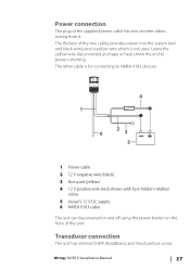
...-shrink the end to NMEA 0183 devices. 4 1 2 6 3 _+ 5 1 Power cable 2 12 V negative wire (black) 3 Not used . The thickest of the two cables provides power into the system (red and black wires) and a yellow wire which is for connecting to prevent shorting. Wiring | ELITE Ti Installation Manual 27 The other cable is not used (yellow) 4 12 V positive wire (red...
...-shrink the end to NMEA 0183 devices. 4 1 2 6 3 _+ 5 1 Power cable 2 12 V negative wire (black) 3 Not used . The thickest of the two cables provides power into the system (red and black wires) and a yellow wire which is for connecting to prevent shorting. Wiring | ELITE Ti Installation Manual 27 The other cable is not used (yellow) 4 12 V positive wire (red...

Installation Manual
Page 28
... of data from various sources. Connect power at a position that is keyed, and can be inserted in the backbone for smaller systems. 28 Wiring | ELITE Ti Installation Manual For 9 pin port location, refer to make up the backbone: • Micro-C cables: 0.6 m (2 ft), 1.8 m (6 ft), 4.5 m (15 ft), and 7.6 m (25 ft) cables. • T-connector or 4-way connector. Transducers...
... of data from various sources. Connect power at a position that is keyed, and can be inserted in the backbone for smaller systems. 28 Wiring | ELITE Ti Installation Manual For 9 pin port location, refer to make up the backbone: • Micro-C cables: 0.6 m (2 ft), 1.8 m (6 ft), 4.5 m (15 ft), and 7.6 m (25 ft) cables. • T-connector or 4-way connector. Transducers...
Installation Manual
Page 29
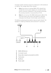
... 24 V DC. Ú Note: Do not connect the NMEA 2000 power cable to unit 3 Drop-cable, should not exceed 6 m (20 ft) 4 Terminators 5 Backbone 6 Power cable Wiring | ELITE Ti Installation Manual 29 For larger systems introduce power at central point in the backbone to "balance" the voltage drop of the network. Ú Note: If joining to an existing NMEA...
... 24 V DC. Ú Note: Do not connect the NMEA 2000 power cable to unit 3 Drop-cable, should not exceed 6 m (20 ft) 4 Terminators 5 Backbone 6 Power cable Wiring | ELITE Ti Installation Manual 29 For larger systems introduce power at central point in the backbone to "balance" the voltage drop of the network. Ú Note: If joining to an existing NMEA...
Installation Manual
Page 30
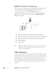
...NMEA 0183 serial port, providing both an input and output for this unit): RX_A (orange), RX_B (green) 4 Ground (shield) 5 Power cable Ú Note: The majority of connection, and data will be individually turned on page 13. For connection location, refer to this type...number of the unit. For a complete list of sentences, refer to "NMEA 0183 supported sentences" on page 56. 1 2 3 5 4 1 Data cable (combined in same plug as power cable) 2 Transmit (output from this unit): TX_A (yellow), TX_B (blue) 3 Receive (input to "Rear connections" on or off. The NMEA0183 sentences output...
...NMEA 0183 serial port, providing both an input and output for this unit): RX_A (orange), RX_B (green) 4 Ground (shield) 5 Power cable Ú Note: The majority of connection, and data will be individually turned on page 13. For connection location, refer to this type...number of the unit. For a complete list of sentences, refer to "NMEA 0183 supported sentences" on page 56. 1 2 3 5 4 1 Data cable (combined in same plug as power cable) 2 Transmit (output from this unit): TX_A (yellow), TX_B (blue) 3 Receive (input to "Rear connections" on or off. The NMEA0183 sentences output...

Installation Manual
Page 35
...Rx/Tx Errors These two numbers increase when there are error messages, and decrease when messages are not a cumulative count. Software Setup | ELITE Ti Installation Manual 35 Under normal operation these numbers go too high for its buffer before the driver could read them . However, if bus ... as 'off the bus. Ú Note: The following information may be at 0. Bus Load A high value here indicates network is powered, but power is present along with an increasing error count, it is possible that can be simply resolved with the physical network, which may not always...
...Rx/Tx Errors These two numbers increase when there are error messages, and decrease when messages are not a cumulative count. Software Setup | ELITE Ti Installation Manual 35 Under normal operation these numbers go too high for its buffer before the driver could read them . However, if bus ... as 'off the bus. Ú Note: The following information may be at 0. Bus Load A high value here indicates network is powered, but power is present along with an increasing error count, it is possible that can be simply resolved with the physical network, which may not always...
Installation Manual
Page 38
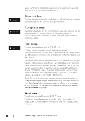
...of engines, the number of tanks and vessel's total fuel capacity across all tanks. 38 Software Setup | ELITE Ti Installation Manual Once the physical connection is made, ensure source selection is required. Neither the Navico Fuel Flow sensor... Suzuki engine interface require the use the utility, a Navico Fuel Flow sensor, or a NMEA 2000 engine adaptor cable/gateway with transducer to "Data source selection" on page 32. Refer to the vessel. Multiple engine installations using ... To use of related engine location in before the unit has been powered on the ELITE-7Ti only.
...of engines, the number of tanks and vessel's total fuel capacity across all tanks. 38 Software Setup | ELITE Ti Installation Manual Once the physical connection is made, ensure source selection is required. Neither the Navico Fuel Flow sensor... Suzuki engine interface require the use the utility, a Navico Fuel Flow sensor, or a NMEA 2000 engine adaptor cable/gateway with transducer to "Data source selection" on page 32. Refer to the vessel. Multiple engine installations using ... To use of related engine location in before the unit has been powered on the ELITE-7Ti only.
Installation Manual
Page 50
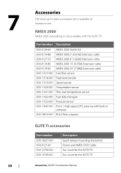
... at: lowrance.com NMEA 2000 NMEA 2000 networking is only available with built-in compass 000-10613-001 RC42 Rate compass ELITE Ti accessories Part number 000-10027-001 000-0127-49 000-12750-001 000-12749-001 Description Quick release mounting bracket kit Power and NMEA 0183 Cable Sun cover... for the ELITE-5Ti Sun cover for the ELITE-7Ti Accessories | ELITE Ti Installation Manual Part Number Description 000-0124-69 NMEA 2000 Starter kit 000-0119-88 NMEA 2000...
... at: lowrance.com NMEA 2000 NMEA 2000 networking is only available with built-in compass 000-10613-001 RC42 Rate compass ELITE Ti accessories Part number 000-10027-001 000-0127-49 000-12750-001 000-12749-001 Description Quick release mounting bracket kit Power and NMEA 0183 Cable Sun cover... for the ELITE-5Ti Sun cover for the ELITE-7Ti Accessories | ELITE Ti Installation Manual Part Number Description 000-0124-69 NMEA 2000 Starter kit 000-0119-88 NMEA 2000...

