SW490 GL BOARD Manual
Page 2
... 23 Controller Programming and Features 24-25 Program Settings 26-27 TROUBLESHOOTING 28-29 MAINTENANCE Operator Maintenance 30 Single Phase Wiring Diagram (SW470 31 Single Phase Wiring Diagram (SW490 32 Three Phase Wiring Diagram (SW490 33 Control Connection Diagrams 34 Repair Parts and Illustrated Parts - Because each application is unique, it . CBeAfoRreTbOegNinInNinVgAAEyoNAuVVTr OTinEEsRtTaRYRllaEtTTioNnIIcSShTecSSIkOtEEhatNMMall cEEomNNponTTents were supplied and received undamaged...
... 23 Controller Programming and Features 24-25 Program Settings 26-27 TROUBLESHOOTING 28-29 MAINTENANCE Operator Maintenance 30 Single Phase Wiring Diagram (SW470 31 Single Phase Wiring Diagram (SW490 32 Three Phase Wiring Diagram (SW490 33 Control Connection Diagrams 34 Repair Parts and Illustrated Parts - Because each application is unique, it . CBeAfoRreTbOegNinInNinVgAAEyoNAuVVTr OTinEEsRtTaRYRllaEtTTioNnIIcSShTecSSIkOtEEhatNMMall cEEomNNponTTents were supplied and received undamaged...
SW490 GL BOARD Manual
Page 15
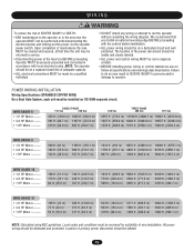
... maintenance to the operator or in the area near the operator MUST not be returned to service. ON POWER WIRING INSTALLATION AVERTISSEMENT Wiring Specifications (STRANDED COPPER WIRE) On a Dual Gate System, each unit must be made by a qualified to do so may be on... power disconnect should be performed until disconnecting the electrical power and locking-out the power via the operator without consulting the wiring diagram. visible and clearly labeled. • Disconnecting power at that you Install an optional reversing edge BEFORE proceeding with local electrical...
... maintenance to the operator or in the area near the operator MUST not be returned to service. ON POWER WIRING INSTALLATION AVERTISSEMENT Wiring Specifications (STRANDED COPPER WIRE) On a Dual Gate System, each unit must be made by a qualified to do so may be on... power disconnect should be performed until disconnecting the electrical power and locking-out the power via the operator without consulting the wiring diagram. visible and clearly labeled. • Disconnecting power at that you Install an optional reversing edge BEFORE proceeding with local electrical...
SW490 GL BOARD Manual
Page 16
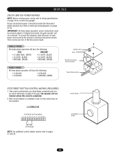
... not function unless this situation, shut off power at main power source and at the operator's electrical disconnect switch. J1 CONNECTOR STOP/RESET BUTTON WIRING 1 2 3 4 5 6 7 8 9 10 STOP/RESET NOTE: For additional control station options refer to terminals 3 and 5 in the... L2 (HOT), BLACK • GROUND, GREEN THREE PHASE All three phase operators will run reversed. WIRING ON/OFF SWITCH POWER WIRING NOTE: Before running power wiring refer to electrical wiring diagrams on pages 31-33. Secure all electrical power connections inside the disconnect switch electrical box. Refer to...
... not function unless this situation, shut off power at main power source and at the operator's electrical disconnect switch. J1 CONNECTOR STOP/RESET BUTTON WIRING 1 2 3 4 5 6 7 8 9 10 STOP/RESET NOTE: For additional control station options refer to terminals 3 and 5 in the... L2 (HOT), BLACK • GROUND, GREEN THREE PHASE All three phase operators will run reversed. WIRING ON/OFF SWITCH POWER WIRING NOTE: Before running power wiring refer to electrical wiring diagrams on pages 31-33. Secure all electrical power connections inside the disconnect switch electrical box. Refer to...
SW490 GL BOARD Manual
Page 31
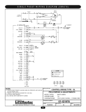
SEE NOTE 2 R 2 SEE NOTE 4 ALARM ASSY 76-G0564 "A" LIMIT CONTACTOR A RPM - OPEN OBS. GL FIELD WIRING & ADJUSTMENTS MODEL TYPES: HORSEPOWER: VOLTAGE/PHASE: SW470 (MSW) 1/2 115V & 230V, 50/60Hz - 1 PHASE ONLY 845 Larch Avenue, Elmhurst, IL 60125 DRAWING NUMBER: DATE: 7/29/03.... SUPPLY RPM GND RPM SENSOR RADIO COMMAND J2 PLUG SHADOW +24 Vdc R3 CLOSE STOP SOFT OPEN R4 HARD OPEN INT. COMMON DC - SINGLE PHASE WIRING DIAGRAM (SW470) 1 PHASE POWER IN SWITCH NOTE 1 MOTOR GROUND GL CONTROL BOARD J2 PLUG 24 Vac - GND LOCK 1 LOCK 2 ALARM 1 ALARM 1 B+ ALARM ASSY 76-G0564 ...
SEE NOTE 2 R 2 SEE NOTE 4 ALARM ASSY 76-G0564 "A" LIMIT CONTACTOR A RPM - OPEN OBS. GL FIELD WIRING & ADJUSTMENTS MODEL TYPES: HORSEPOWER: VOLTAGE/PHASE: SW470 (MSW) 1/2 115V & 230V, 50/60Hz - 1 PHASE ONLY 845 Larch Avenue, Elmhurst, IL 60125 DRAWING NUMBER: DATE: 7/29/03.... SUPPLY RPM GND RPM SENSOR RADIO COMMAND J2 PLUG SHADOW +24 Vdc R3 CLOSE STOP SOFT OPEN R4 HARD OPEN INT. COMMON DC - SINGLE PHASE WIRING DIAGRAM (SW470) 1 PHASE POWER IN SWITCH NOTE 1 MOTOR GROUND GL CONTROL BOARD J2 PLUG 24 Vac - GND LOCK 1 LOCK 2 ALARM 1 ALARM 1 B+ ALARM ASSY 76-G0564 ...
SW490 GL BOARD Manual
Page 32
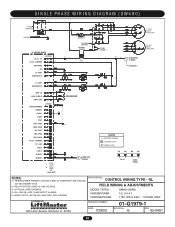
... Avenue, Elmhurst, IL 60125 DRAWING NUMBER: DATE: 7/29/03 01-G1979-1 REVISION: E ECN: 03-0401 32 SINGLE PHASE WIRING DIAGRAM (SW490) 1 PHASE POWER IN (GN) GROUND (W) (GN) GL CONTROL BOARD 24 Vac - APPLICATIONS: CONTROL WIRING TYPE - SUPPLY RPM GND RADIO COMMAND J2 PLUG SHADOW R3 +24 Vdc CLOSE STOP SOFT OPEN HARD OPEN INT...
... Avenue, Elmhurst, IL 60125 DRAWING NUMBER: DATE: 7/29/03 01-G1979-1 REVISION: E ECN: 03-0401 32 SINGLE PHASE WIRING DIAGRAM (SW490) 1 PHASE POWER IN (GN) GROUND (W) (GN) GL CONTROL BOARD 24 Vac - APPLICATIONS: CONTROL WIRING TYPE - SUPPLY RPM GND RADIO COMMAND J2 PLUG SHADOW R3 +24 Vdc CLOSE STOP SOFT OPEN HARD OPEN INT...
SW490 GL BOARD Manual
Page 33
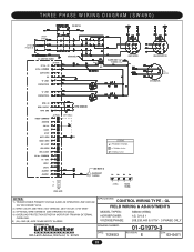
...& 575V - 3 PHASE ONLY DRAWING NUMBER: 01-G1979-3 845 Larch Avenue, Elmhurst, IL 60125 DATE: 7/29/03 REVISION: E ECN: 03-0401 33 THREE PHASE WIRING DIAGRAM (SW490) SEE NOTE 4 ' ' ' ' 3 PHASE POWER IN ON/OFF SWITCH GL CONTROL BOARD 24 Vac - COMMON DC - LOOP OBS. GND LOCK 1 LOCK 2...R4 24 Vac RADIO SIGNAL NOTES: 1) TRANSFORMER PRIMARY VOLTAGE SAME AS OPERATOR LINE VOLTAGE 24V SECONDARY 60VA. 2) WIRE COLOR: 208V RED, 230V ORANGE, 460V VIOLET, 575V GRAY 3) OPTIONAL WIRE HARNESS (SEE DRAWING 90-G0532). 4) OVERLOAD PROTECTION EITHER IN MOTOR OR FROM AN EXTERNAL OVERLOAD. 5) (B+)...
...& 575V - 3 PHASE ONLY DRAWING NUMBER: 01-G1979-3 845 Larch Avenue, Elmhurst, IL 60125 DATE: 7/29/03 REVISION: E ECN: 03-0401 33 THREE PHASE WIRING DIAGRAM (SW490) SEE NOTE 4 ' ' ' ' 3 PHASE POWER IN ON/OFF SWITCH GL CONTROL BOARD 24 Vac - COMMON DC - LOOP OBS. GND LOCK 1 LOCK 2...R4 24 Vac RADIO SIGNAL NOTES: 1) TRANSFORMER PRIMARY VOLTAGE SAME AS OPERATOR LINE VOLTAGE 24V SECONDARY 60VA. 2) WIRE COLOR: 208V RED, 230V ORANGE, 460V VIOLET, 575V GRAY 3) OPTIONAL WIRE HARNESS (SEE DRAWING 90-G0532). 4) OVERLOAD PROTECTION EITHER IN MOTOR OR FROM AN EXTERNAL OVERLOAD. 5) (B+)...
SW490 GL BOARD Manual
Page 34
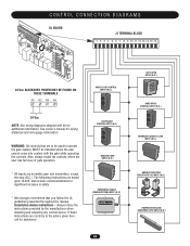
...include recommendations for significant increase in safety. * We strongly recommend that are to be used to the advice given here, call for wiring distances and wire gauge information. Also, always install the controls where the user has full view of gate operation. * All inputs are contrary to ... UL guidelines presented throughout the manual. CONTROL CONNECTION DIAGRAMS GL BOARD J1 TERMINAL BLOCK 1 2 3 4 5 6 7 8 9 10 11 12 13 14 15 16 24 Vac ACCESSORY POWER MAY BE FOUND ON THESE TERMINALS R1 R2 R3 R4 24 Vac NOTE: See wiring diagrams shipped with the gate while operating the controls.
...include recommendations for significant increase in safety. * We strongly recommend that are to be used to the advice given here, call for wiring distances and wire gauge information. Also, always install the controls where the user has full view of gate operation. * All inputs are contrary to ... UL guidelines presented throughout the manual. CONTROL CONNECTION DIAGRAMS GL BOARD J1 TERMINAL BLOCK 1 2 3 4 5 6 7 8 9 10 11 12 13 14 15 16 24 Vac ACCESSORY POWER MAY BE FOUND ON THESE TERMINALS R1 R2 R3 R4 24 Vac NOTE: See wiring diagrams shipped with the gate while operating the controls.

SW490 S3 BOARD Manual
Page 18
18 Installation Electrical Power Connections CAUTION Make sure power is properly grounded. Secure all electrical power connections inside the power wiring compartment. Then, reverse any two of the three power leads. If they are phased wrong the gate operator will have - L1 (neutral... must be properly phased. Figure 15 0 1 -0 6 6 5 F1 0 Doc 01-G0665 Rev C All three phase operators will have - Use the electrical wiring diagram supplied with this situation, disconnect power a main power source and at the operator's electrical disconnect switch before proceeding.
18 Installation Electrical Power Connections CAUTION Make sure power is properly grounded. Secure all electrical power connections inside the power wiring compartment. Then, reverse any two of the three power leads. If they are phased wrong the gate operator will have - L1 (neutral... must be properly phased. Figure 15 0 1 -0 6 6 5 F1 0 Doc 01-G0665 Rev C All three phase operators will have - Use the electrical wiring diagram supplied with this situation, disconnect power a main power source and at the operator's electrical disconnect switch before proceeding.
SW490 S3 BOARD Manual
Page 21
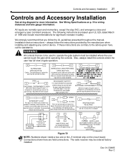
... open and momentary, except the stop (NC), and emergency close directions. The radio receiver may be used with power wiring. Also, always install the controls where the user has full view of 1999 and include recommendations for significant increase in safety...instructions - For warning devices, call for persons. Controls and Accessory Installation 21 Controls and Accessory Installation See wiring diagram for wiring distances and wire gauge information. See Wiring Specifications on the close ) the gate if active. All inputs are field connections. We strongly recommend that...
... open and momentary, except the stop (NC), and emergency close directions. The radio receiver may be used with power wiring. Also, always install the controls where the user has full view of 1999 and include recommendations for significant increase in safety...instructions - For warning devices, call for persons. Controls and Accessory Installation 21 Controls and Accessory Installation See wiring diagram for wiring distances and wire gauge information. See Wiring Specifications on the close ) the gate if active. All inputs are field connections. We strongly recommend that...


