RSL12UL Wiring Diagram
Page 1
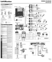
.... CODE SEQUENCE NUMBER The first number shown is NOT a single 12V battery on a 24V system. 43 Exit Loop Error 44 Shadow Loop Error Interrupt Loop Error 45 Failure or missing loop (SHORT or OPEN LiftMaster Plug-in the open direction 61 CLOSE EYE/INTERRUPT held more than 3...engage arm. Operator may be set limits. If limits are monitored. Replace APE assembly. 99 Normal Operation No action required WIRING DIAGRAM Model RSL12UL COAXIAL CABLE ANTENNA Control Board DIAGNOSTICS J25 (see below allowable level. Make sure there is engaged and free to move . Control Station ...
.... CODE SEQUENCE NUMBER The first number shown is NOT a single 12V battery on a 24V system. 43 Exit Loop Error 44 Shadow Loop Error Interrupt Loop Error 45 Failure or missing loop (SHORT or OPEN LiftMaster Plug-in the open direction 61 CLOSE EYE/INTERRUPT held more than 3...engage arm. Operator may be set limits. If limits are monitored. Replace APE assembly. 99 Normal Operation No action required WIRING DIAGRAM Model RSL12UL COAXIAL CABLE ANTENNA Control Board DIAGNOSTICS J25 (see below allowable level. Make sure there is engaged and free to move . Control Station ...
Owners Manual - English French
Page 2
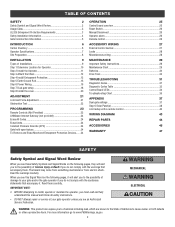
... Install the cover 20 ADJUSTMENT 21 Limit and Force Adjustment 21 Obstruction Test 22 PROGRAMMING 23 Remote Controls (Not Provided 23 LiftMaster Internet Gateway (not provided 24 Erase All Codes 24 Erase limits 24 Constant Pressure Override (CPO 24 Gate hold open feature... WIRING 27 External control devices 27 Locks 28 Miscellaneous wiring 28 MAINTENANCE 29 Important Safety Instructions 29 Maintenance Chart 29 Batteries 30 Drive Train 30 TROUBLESHOOTING 31 Diagnostic Codes 31 Diagnostic Codes Table 32 Control Board LEDs 34 Troubleshooting Chart 35 ...
... Install the cover 20 ADJUSTMENT 21 Limit and Force Adjustment 21 Obstruction Test 22 PROGRAMMING 23 Remote Controls (Not Provided 23 LiftMaster Internet Gateway (not provided 24 Erase All Codes 24 Erase limits 24 Constant Pressure Override (CPO 24 Gate hold open feature... WIRING 27 External control devices 27 Locks 28 Miscellaneous wiring 28 MAINTENANCE 29 Important Safety Instructions 29 Maintenance Chart 29 Batteries 30 Drive Train 30 TROUBLESHOOTING 31 Diagnostic Codes 31 Diagnostic Codes Table 32 Control Board LEDs 34 Troubleshooting Chart 35 ...

Owners Manual - English French
Page 7
...) protection device. INTRODUCTION Operator Specifications Usage Classification Class I & II Main AC Supply 120 Vac, .5 Amps (6.5 Amps including Accessory Outlets) System Operating Voltage 12 Vdc Battery Run / Battery Backup Accessory Power 12 Vdc, 500mA max. up to 140°F) Expansion Board Optional External Entrapment Protection Device Inputs (non-contact Main board - Maximum Gate...
...) protection device. INTRODUCTION Operator Specifications Usage Classification Class I & II Main AC Supply 120 Vac, .5 Amps (6.5 Amps including Accessory Outlets) System Operating Voltage 12 Vdc Battery Run / Battery Backup Accessory Power 12 Vdc, 500mA max. up to 140°F) Expansion Board Optional External Entrapment Protection Device Inputs (non-contact Main board - Maximum Gate...
Owners Manual - English French
Page 9
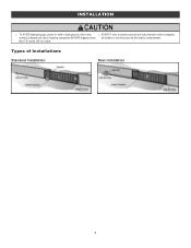
Types of Installations Standard Installation Rear Installation 9 INSTALLATION l To AVOID damaging gas, power or other underground utility lines, l ALWAYS wear protective gloves and eye protection when changing contact underground utility locating companies BEFORE digging more the battery or working around the battery compartment. than 18 inches (46 cm) deep.
Types of Installations Standard Installation Rear Installation 9 INSTALLATION l To AVOID damaging gas, power or other underground utility lines, l ALWAYS wear protective gloves and eye protection when changing contact underground utility locating companies BEFORE digging more the battery or working around the battery compartment. than 18 inches (46 cm) deep.
Owners Manual - English French
Page 15
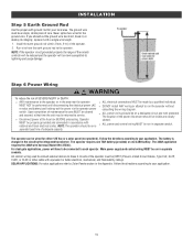
...power wiring should be wired for either 120 Vac or a solar panel (not provided). The battery is not grounded properly the range of wire. The operator requires one 7AH battery (provided) or one 33AH battery. INSTALLATION Step 5 Earth Ground Rod Use the proper earth ground rod for the ground wire....used to connect external devices to Class 2 circuits of the power disconnect should be returned to run the operator without or solar and battery) and locking-out the power via the operator power consulting the wiring diagram. Main power supply and control wiring MUST be properly ...
...power wiring should be wired for either 120 Vac or a solar panel (not provided). The battery is not grounded properly the range of wire. The operator requires one 7AH battery (provided) or one 33AH battery. INSTALLATION Step 5 Earth Ground Rod Use the proper earth ground rod for the ground wire....used to connect external devices to Class 2 circuits of the power disconnect should be returned to run the operator without or solar and battery) and locking-out the power via the operator power consulting the wiring diagram. Main power supply and control wiring MUST be properly ...
Owners Manual - English French
Page 17
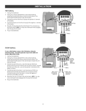
... J15 plug to the negative (-) terminal of the black (-) wire to the positive (+) terminal of the 7AH battery, follow the instructions below. Plug in the transformer. 33AH battery To use a 33AH battery in the transformer. 17 The 33AH application requires the 33AH wire harness (Model K94-37236). 1. Discard this J15... This disconnects the ac/dc power to the control board. Connect the black wire from the J15 plug to the negative (-) terminal on the battery as shown. Connect one end of the black (-) wire from the new 33AH wire harness kit to the red wire from the new J15 plug...
... J15 plug to the negative (-) terminal of the black (-) wire to the positive (+) terminal of the 7AH battery, follow the instructions below. Plug in the transformer. 33AH battery To use a 33AH battery in the transformer. 17 The 33AH application requires the 33AH wire harness (Model K94-37236). 1. Discard this J15... This disconnects the ac/dc power to the control board. Connect the black wire from the J15 plug to the negative (-) terminal on the battery as shown. Connect one end of the black (-) wire from the new 33AH wire harness kit to the red wire from the new J15 plug...
Owners Manual - English French
Page 18
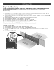
... LEARN button again on the same operator. Press and release the LEARN button again on the primary operator. The green XMITTER LED will have a longer battery standby time than wireless applications. INSTALLATION Step 7 Dual Gate Setup There are set on the primary operator. 2. Do not use wired and wireless communication simultaneously...
... LEARN button again on the same operator. Press and release the LEARN button again on the primary operator. The green XMITTER LED will have a longer battery standby time than wireless applications. INSTALLATION Step 7 Dual Gate Setup There are set on the primary operator. 2. Do not use wired and wireless communication simultaneously...
Owners Manual - English French
Page 25
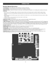
...button control, or CLOSE command on next CLOSE command until AC power is reset by a "12" which indicates the operator type as RSL12UL. Rotate the TIMER-TOCLOSE dial to the OFF position, then the gate will show after a specified time period. See Force Adjustment section.... the Troubleshooting section. 11 DIAGNOSTICS Display: The diagnostics display will remain open controls, loops, close edges, and close the gate. l Critically low battery is less than 11.5 V 5 BIPART DELAY Switch: The LOCK/BIPART DELAY switch is a loss of the operator. See Adjust Limits section. ...
...button control, or CLOSE command on next CLOSE command until AC power is reset by a "12" which indicates the operator type as RSL12UL. Rotate the TIMER-TOCLOSE dial to the OFF position, then the gate will show after a specified time period. See Force Adjustment section.... the Troubleshooting section. 11 DIAGNOSTICS Display: The diagnostics display will remain open controls, loops, close edges, and close the gate. l Critically low battery is less than 11.5 V 5 BIPART DELAY Switch: The LOCK/BIPART DELAY switch is a loss of the operator. See Adjust Limits section. ...

Owners Manual - English French
Page 26
... reset after doing this. When the inherent force of the operator and serves several functions. The operator alarm will beep 3 times with a command if the battery is in the open position, activation of the remote control button will stop a moving gate during a normal open cycle another activation of the remote control...
... reset after doing this. When the inherent force of the operator and serves several functions. The operator alarm will beep 3 times with a command if the battery is in the open position, activation of the remote control button will stop a moving gate during a normal open cycle another activation of the remote control...
Owners Manual - English French
Page 29
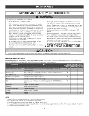
... maintenance checks. l l ALWAYS wear protective gloves and eye protection when changing the battery or working around the battery compartment. ALWAYS disconnect the batteries to the control board and DOES NOT turn off battery power. Operator moving. l If lubricating chain, use ONLY LiftMaster part 29-NP712 for X proper operation Warning Signs Make sure they are no...
... maintenance checks. l l ALWAYS wear protective gloves and eye protection when changing the battery or working around the battery compartment. ALWAYS disconnect the batteries to the control board and DOES NOT turn off battery power. Operator moving. l If lubricating chain, use ONLY LiftMaster part 29-NP712 for X proper operation Warning Signs Make sure they are no...
Owners Manual - English French
Page 30
... LiftMaster part 29-NP712 for every 10 feet of the 7AH battery. The operator comes with a command if the battery is low. NOTE: The chain should be used in extremely cold temperatures. To tighten the drive chain adjust either of properly. For best performance, the batteries should... have no more than 1 inch of sag for replacement batteries. One 33AH Battery (A12330SGLPK), with 33AH Battery Harness (K94-37236) may be replaced every 3 years. Batteries do not perform well in place of chain length. 30...
... LiftMaster part 29-NP712 for every 10 feet of the 7AH battery. The operator comes with a command if the battery is low. NOTE: The chain should be used in extremely cold temperatures. To tighten the drive chain adjust either of properly. For best performance, the batteries should... have no more than 1 inch of sag for replacement batteries. One 33AH Battery (A12330SGLPK), with 33AH Battery Harness (K94-37236) may be replaced every 3 years. Batteries do not perform well in place of chain length. 30...
Owners Manual - English French
Page 31
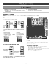
... seconds. 2. The display will show "Er" then "CL" alternately for six seconds. For continued protection against fire and electrocution: l DISCONNECT power (AC or solar and battery) BEFORE installing or servicing operator. The code history has now been reset and the display will show "- -" until a new code occurs. 3.
... seconds. 2. The display will show "Er" then "CL" alternately for six seconds. For continued protection against fire and electrocution: l DISCONNECT power (AC or solar and battery) BEFORE installing or servicing operator. The code history has now been reset and the display will show "- -" until a new code occurs. 3.
Owners Manual - English French
Page 32
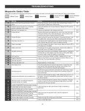
...has experienced an internal failure. AC/DC board supply dipped below allowable level. If a code is NOT a single 12V battery on a 12V system. LiftMaster Plug-in wireless edge. Rundistance can be at boot up Exit Loop Error Shadow Loop Error Interrupt Loop Error Wireless edge... battery low Run-Distance Error Brownout occurred Wireless Second Operator Communication Error Minimum number of travel (re-adjust mounting). Slide ...
...has experienced an internal failure. AC/DC board supply dipped below allowable level. If a code is NOT a single 12V battery on a 12V system. LiftMaster Plug-in wireless edge. Rundistance can be at boot up Exit Loop Error Shadow Loop Error Interrupt Loop Error Wireless edge... battery low Run-Distance Error Brownout occurred Wireless Second Operator Communication Error Minimum number of travel (re-adjust mounting). Slide ...
Owners Manual - English French
Page 34
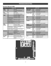
... LEDs INPUT OFF POWER ON STATUS LEDS OFF state AC charger or Solar power available BATT OFF CHARGING ON Not charging Three stage battery charging TIMER OFF ON MEDIUM BLINK (1 blink per second) The timer is disabled The timer is enabled The timer is running FAST ...single blink per second) entrapment) FASTEST BLINK (8 The operator is in E2 (double blinks per second) entrapment) OFF No battery error ON Battery low MEDIUM BLINK (1 Battery critically low blink per second) OFF Accessory power is okay ON Accessory overload protector opened OPEN, CLOSE, STOP INPUT FIRE DEPT ...
... LEDs INPUT OFF POWER ON STATUS LEDS OFF state AC charger or Solar power available BATT OFF CHARGING ON Not charging Three stage battery charging TIMER OFF ON MEDIUM BLINK (1 blink per second) The timer is disabled The timer is enabled The timer is running FAST ...single blink per second) entrapment) FASTEST BLINK (8 The operator is in E2 (double blinks per second) entrapment) OFF No battery error ON Battery low MEDIUM BLINK (1 Battery critically low blink per second) OFF Accessory power is okay ON Accessory overload protector opened OPEN, CLOSE, STOP INPUT FIRE DEPT ...
Owners Manual - English French
Page 35
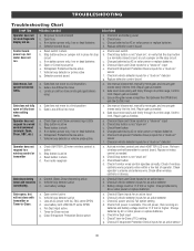
... on " detector g. Replace defective control board a. Gate must be 11.5 Vdc or higher. b. Stop button is active c. If on batteries and battery voltage must move gate, and ensure gate moves easily limit to a wireless control or transmitter a. Vehicle loop detector or vehicle probe active ... Stop button active or jumper not in place for an active input b. Vehicle loop detector or probe active g. Charges batteries by AC or solar power or replace batteries d. Check all vehicle detector inputs for a "stuck on " sensor f. Repair gate as needed . Check other wireless...
... on " detector g. Replace defective control board a. Gate must be 11.5 Vdc or higher. b. Stop button is active c. If on batteries and battery voltage must move gate, and ensure gate moves easily limit to a wireless control or transmitter a. Vehicle loop detector or vehicle probe active ... Stop button active or jumper not in place for an active input b. Vehicle loop detector or probe active g. Charges batteries by AC or solar power or replace batteries d. Check all vehicle detector inputs for a "stuck on " sensor f. Repair gate as needed . Check other wireless...
Owners Manual - English French
Page 36
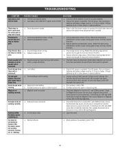
...power terminals). Press the reset button to stop , and may reverse direction. If no AC power, then running on batteries and battery voltage must be 11.5 Vdc or higher. Check that activating edge sensor causes moving gate to open or close is... that Maglock has power (do not power solenoid from control board accessory power terminals). b. POSSIBLE CAUSES a. Charge batteries by AC or solar power or replace batteries a. Check photoelectric sensor wiring. Replace defective edge sensor. Check if AC power is available. and COM terminals. ...
...power terminals). Press the reset button to stop , and may reverse direction. If no AC power, then running on batteries and battery voltage must be 11.5 Vdc or higher. Check that activating edge sensor causes moving gate to open or close is... that Maglock has power (do not power solenoid from control board accessory power terminals). b. POSSIBLE CAUSES a. Charge batteries by AC or solar power or replace batteries a. Check photoelectric sensor wiring. Replace defective edge sensor. Check if AC power is available. and COM terminals. ...
Owners Manual - English French
Page 37
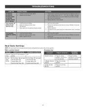
...Reduce the accessory power draw by using LiftMaster low power accessories c. Program remote controls 51 to 100 to the secondary operator Program to Accessory power not working correctly, turning off, or resetting. Excessive accessory power draw c. Use batteries with higher amp hour (AH) rating ...Synchronized Close: ON Bi-Part Delay: OFF (will open first and close last) Tandem Mode: OFF Synchronized Close: ON LiftMaster Internet Gateway Garage and Gate Monitor PRIMARY OPERATOR SECONDARY OPERATOR Program remote controls 1 to 50 to primary operator. 37 Defective control board...
...Reduce the accessory power draw by using LiftMaster low power accessories c. Program remote controls 51 to 100 to the secondary operator Program to Accessory power not working correctly, turning off, or resetting. Excessive accessory power draw c. Use batteries with higher amp hour (AH) rating ...Synchronized Close: ON Bi-Part Delay: OFF (will open first and close last) Tandem Mode: OFF Synchronized Close: ON LiftMaster Internet Gateway Garage and Gate Monitor PRIMARY OPERATOR SECONDARY OPERATOR Program remote controls 1 to 50 to primary operator. 37 Defective control board...
Owners Manual - English French
Page 38
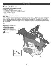
... vary based on the map below. SEE ACCESSORIES Solar Application requirements: l A minimum of one 33AH battery l A heater cannot be installed in parallel (Model SP10W12V). Solar zones 38 l One 7AH battery or one 10W solar panel (Model SP10W12V). The cycles/day ratings are based upon the average solar radiation... and the temperature effects on batteries in northern climates due to cold weather and a reduced number of hours of heavy fog, lake effect snow, or rain. Local ...
... vary based on the map below. SEE ACCESSORIES Solar Application requirements: l A minimum of one 33AH battery l A heater cannot be installed in parallel (Model SP10W12V). Solar zones 38 l One 7AH battery or one 10W solar panel (Model SP10W12V). The cycles/day ratings are based upon the average solar radiation... and the temperature effects on batteries in northern climates due to cold weather and a reduced number of hours of heavy fog, lake effect snow, or rain. Local ...
Owners Manual - English French
Page 39
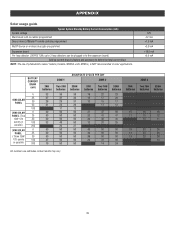
Actual results may vary. 39 APPENDIX Solar usage guide Typical System Standby Battery Current Consumption (mA) System voltage Main board with no radios programmed One or more LiftMaster® remote controls programmed MyQ® device or wireless dual gate programmed Expansion board Per loop detector LOOPDETLM (... photoelectric sensor heaters (models LMRRUL and LMTBUL) is NOT recommended in solar applications. 12V 4.2 mA +1.5 mA +3.9 mA +18.5 mA +6.6 mA BATTERY CURRENT DRAW (mA) 6 25 10W SOLAR PANEL 30 50 100 20W SOLAR 6 PANEL (Two 25 10W 12V 30 panels in 100 parallel) 200...
Actual results may vary. 39 APPENDIX Solar usage guide Typical System Standby Battery Current Consumption (mA) System voltage Main board with no radios programmed One or more LiftMaster® remote controls programmed MyQ® device or wireless dual gate programmed Expansion board Per loop detector LOOPDETLM (... photoelectric sensor heaters (models LMRRUL and LMTBUL) is NOT recommended in solar applications. 12V 4.2 mA +1.5 mA +3.9 mA +18.5 mA +6.6 mA BATTERY CURRENT DRAW (mA) 6 25 10W SOLAR PANEL 30 50 100 20W SOLAR 6 PANEL (Two 25 10W 12V 30 panels in 100 parallel) 200...
Owners Manual - English French
Page 40
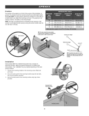
Secure the solar panel to the success of the installation. If the panel(s) is not casting a shadow, the battery is critical to the mounting bracket using lag screws provided. 40 Use a compass to the mounting surface using the hex bolts, hex nuts and washers ...
Secure the solar panel to the success of the installation. If the panel(s) is not casting a shadow, the battery is critical to the mounting bracket using lag screws provided. 40 Use a compass to the mounting surface using the hex bolts, hex nuts and washers ...


