RSL12UL Wiring Diagram
Page 1
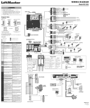
...5 Stop/Reset RESET SWITCH Motor APS ENCODER HOT GROUND NEUTRAL Incoming Power LiftMaster.com © 2018, LiftMaster All Rights Reserved 01-39240-4 May have a 12V battery on expansion board; Wireless Second Operator Communication Error Check the second operator for obstruction. Minimum... occurred, no action required. Replace APE assembly. 99 Normal Operation No action required WIRING DIAGRAM Model RSL12UL COAXIAL CABLE ANTENNA Control Board DIAGNOSTICS J25 (see below allowable level. check for open direction 61 CLOSE EYE/INTERRUPT held more than...
...5 Stop/Reset RESET SWITCH Motor APS ENCODER HOT GROUND NEUTRAL Incoming Power LiftMaster.com © 2018, LiftMaster All Rights Reserved 01-39240-4 May have a 12V battery on expansion board; Wireless Second Operator Communication Error Check the second operator for obstruction. Minimum... occurred, no action required. Replace APE assembly. 99 Normal Operation No action required WIRING DIAGRAM Model RSL12UL COAXIAL CABLE ANTENNA Control Board DIAGNOSTICS J25 (see below allowable level. check for open direction 61 CLOSE EYE/INTERRUPT held more than...
Owners Manual - English French
Page 2
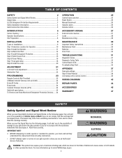
... Install the cover 20 ADJUSTMENT 21 Limit and Force Adjustment 21 Obstruction Test 22 PROGRAMMING 23 Remote Controls (Not Provided 23 LiftMaster Internet Gateway (not provided 24 Erase All Codes 24 Erase limits 24 Constant Pressure Override (CPO 24 Gate hold open feature ...Important Safety Instructions 29 Maintenance Chart 29 Batteries 30 Drive Train 30 TROUBLESHOOTING 31 Diagnostic Codes 31 Diagnostic Codes Table 32 Control Board LEDs 34 Troubleshooting Chart 35 APPENDIX 37 Dual gate settings 37 Step 6 Solar Panel(s 38 Limit setup with a remote ...
... Install the cover 20 ADJUSTMENT 21 Limit and Force Adjustment 21 Obstruction Test 22 PROGRAMMING 23 Remote Controls (Not Provided 23 LiftMaster Internet Gateway (not provided 24 Erase All Codes 24 Erase limits 24 Constant Pressure Override (CPO 24 Gate hold open feature ...Important Safety Instructions 29 Maintenance Chart 29 Batteries 30 Drive Train 30 TROUBLESHOOTING 31 Diagnostic Codes 31 Diagnostic Codes Table 32 Control Board LEDs 34 Troubleshooting Chart 35 APPENDIX 37 Dual gate settings 37 Step 6 Solar Panel(s 38 Limit setup with a remote ...

Owners Manual - English French
Page 7
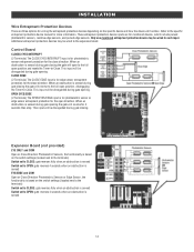
Expansion board - Maximum Gate Weight 800 lbs (363.6 kg) Minimum Gate Travel Distance 25 feet (7.62 m) Maximum Gate Travel Distance 50 feet (15.24 m) Maximum Gate Travel ...°F) With Optional Heater: -40°C to 60°C (-40°F to 2 close or open and up to 140°F) Expansion Board Optional External Entrapment Protection Device Inputs (non-contact Main board - up to 4 edge sensors using wireless edge sensor kit model LMWEKITU . 7 for ON + SW (switched) Solar Power Max 12 Vdc...
Expansion board - Maximum Gate Weight 800 lbs (363.6 kg) Minimum Gate Travel Distance 25 feet (7.62 m) Maximum Gate Travel Distance 50 feet (15.24 m) Maximum Gate Travel ...°F) With Optional Heater: -40°C to 60°C (-40°F to 2 close or open and up to 140°F) Expansion Board Optional External Entrapment Protection Device Inputs (non-contact Main board - up to 4 edge sensors using wireless edge sensor kit model LMWEKITU . 7 for ON + SW (switched) Solar Power Max 12 Vdc...
Owners Manual - English French
Page 14
...This input will be disregarded during gate opening the gate will open to the full open position and resets the Timer-to the expansion board. Additional entrapment protection devices may be wired to -Close. When an obstruction is sensed during gate opening . This input will be disregarded... during gate closing . OPEN EYES/EDGE (2 Terminals) The OPEN EYES/EDGE input is sensed 14 Expansion Board (not provided) EYE ONLY and COM Open or Close Direction Photoelectric Sensors, the functionality is based on the switch settings (located next to...
...This input will be disregarded during gate opening the gate will open to the full open position and resets the Timer-to the expansion board. Additional entrapment protection devices may be wired to -Close. When an obstruction is sensed during gate opening . This input will be disregarded... during gate closing . OPEN EYES/EDGE (2 Terminals) The OPEN EYES/EDGE input is sensed 14 Expansion Board (not provided) EYE ONLY and COM Open or Close Direction Photoelectric Sensors, the functionality is based on the switch settings (located next to...
Owners Manual - English French
Page 17
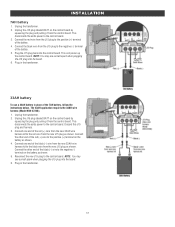
... Connect one end of the black (-) wire from the new 33AH wire harness kit to the black wire from the J15 plug to the control board. Connect the black wire from the new J15 plug as shown. 5. Connect the other end of the battery. 5. Plug the J15 plug back into the... board. 6. Unplug the transformer. 2. Connect the other end of the 7AH battery, follow the instructions below. Unplug the J15 plug labeled BATT on the battery as ...
... Connect one end of the black (-) wire from the new 33AH wire harness kit to the black wire from the J15 plug to the control board. Connect the black wire from the new J15 plug as shown. 5. Connect the other end of the battery. 5. Plug the J15 plug back into the... board. 6. Unplug the transformer. 2. Connect the other end of the 7AH battery, follow the instructions below. Unplug the J15 plug labeled BATT on the battery as ...
Owners Manual - English French
Page 18
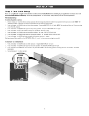
... OPEN test button to the primary operator. Press and hold the LEARN button for the other operator. 18 NOTE: We recommend that all accessories and board configurations are two options for dual gate communication: wired or wireless. Press and release the LEARN button again on the primary operator. 2. NOTE: The operator...
... OPEN test button to the primary operator. Press and hold the LEARN button for the other operator. 18 NOTE: We recommend that all accessories and board configurations are two options for dual gate communication: wired or wireless. Press and release the LEARN button again on the primary operator. 2. NOTE: The operator...
Owners Manual - English French
Page 19
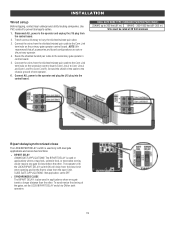
... GATE APPLICATIONS: The BIPART DELAY is also used in applications where one gate to the chassis ground of the gates, set on the secondary control board (Com Link A to Com Link A and Com Link B to bury the shielded twisted pair cable. 3. SLIDE GATE APPLICATIONS: Not applicable, set to the... operator and plug the J15 plug into the control board. Trench across driveway to Com Link B). The operator with the LOCK/BIPART DELAY switch ON will delay from the close limit when opening and be...
... GATE APPLICATIONS: The BIPART DELAY is also used in applications where one gate to the chassis ground of the gates, set on the secondary control board (Com Link A to Com Link A and Com Link B to bury the shielded twisted pair cable. 3. SLIDE GATE APPLICATIONS: Not applicable, set to the... operator and plug the J15 plug into the control board. Trench across driveway to Com Link B). The operator with the LOCK/BIPART DELAY switch ON will delay from the close limit when opening and be...
Owners Manual - English French
Page 21
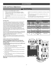
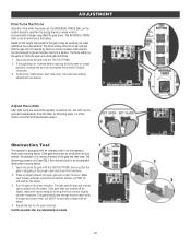
... SET OPEN and SET CLOSE buttons simultaneously to move the gate to the open limit and closed limit MUST be fine tuned using the control board (below) or a remote control (refer to Limit Setup with electronic controls to make travel limits) is adjusted automatically when you to program ...setting the limits and force. l After ANY adjustments are installed. The force is adjusted, the other limit. 5. l Too much force on the control board (refer to Fine Tune the Force section) to OPEN, CLOSE, and STOP. For slide gate applications the open or close position. NOTE: The TEST buttons...
... SET OPEN and SET CLOSE buttons simultaneously to move the gate to the open limit and closed limit MUST be fine tuned using the control board (below) or a remote control (refer to Limit Setup with electronic controls to make travel limits) is adjusted automatically when you to program ...setting the limits and force. l After ANY adjustments are installed. The force is adjusted, the other limit. 5. l Too much force on the control board (refer to Fine Tune the Force section) to OPEN, CLOSE, and STOP. For slide gate applications the open or close position. NOTE: The TEST buttons...
Owners Manual - English French
Page 22
... and reverse upon contact with the TEST BUTTONS, ensuring that the gate is used for the open gate and a rigid structure. Based on the control board is stopping at the factory. The force setting should stop . Repeat the test for fine tuning the force where wind or environmental changes may be...
... and reverse upon contact with the TEST BUTTONS, ensuring that the gate is used for the open gate and a rigid structure. Based on the control board is stopping at the factory. The force setting should stop . Repeat the test for fine tuning the force where wind or environmental changes may be...
Owners Manual - English French
Page 24
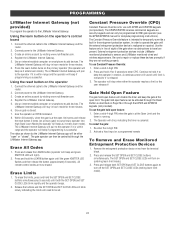
The LiftMaster Internet Gateway will light). 2. Using the reset button on the opertaor's control board 1. Connect power to add devices. The gate operator can only be set. Press and release the LEARN button (operator will ...with KPW5 and KPW250 keypads (not provided). Constant Pressure Override (CPO) Constant Pressure Override is running 2. External entrapment protection devices include LiftMaster monitored photoelectric sensors and LiftMaster monitored wired and wireless edge sensors. The operator will chirp indicating the timer is closed ". Enter a valid 4-digit PIN when ...
The LiftMaster Internet Gateway will light). 2. Using the reset button on the opertaor's control board 1. Connect power to add devices. The gate operator can only be set. Press and release the LEARN button (operator will ...with KPW5 and KPW250 keypads (not provided). Constant Pressure Override (CPO) Constant Pressure Override is running 2. External entrapment protection devices include LiftMaster monitored photoelectric sensors and LiftMaster monitored wired and wireless edge sensors. The operator will chirp indicating the timer is closed ". Enter a valid 4-digit PIN when ...
Owners Manual - English French
Page 25
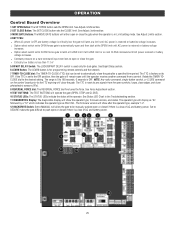
.... See Adjust Limits section. 4 BATT FAIL: l When AC power is OFF and battery voltage is critically low the gate will display as RSL12UL. l Option select switch set to OPEN forces gate to automatically open or closed if there is factory set to automatically close the gate after ...CLOSE command until AC power is in the Troubleshooting section. 11 DIAGNOSTICS Display: The diagnostics display will remain open or close the gate. OPERATION Control Board Overview 1 SET OPEN Button: The SET OPEN button sets the OPEN limit. See Adjust Limits section. 3 MOVE GATE Buttons: The MOVE GATE...
.... See Adjust Limits section. 4 BATT FAIL: l When AC power is OFF and battery voltage is critically low the gate will display as RSL12UL. l Option select switch set to OPEN forces gate to automatically open or closed if there is factory set to automatically close the gate after ...CLOSE command until AC power is in the Troubleshooting section. 11 DIAGNOSTICS Display: The diagnostics display will remain open or close the gate. OPERATION Control Board Overview 1 SET OPEN Button: The SET OPEN button sets the OPEN limit. See Adjust Limits section. 3 MOVE GATE Buttons: The MOVE GATE...
Owners Manual - English French
Page 27
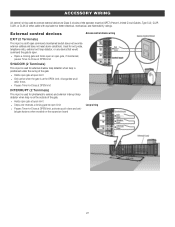
... gate. ACCESSORY WIRING All control wiring used to connect external devices to Class 2 circuits of the gate. SHADOW (2 Terminals) This input is on the expansion board Loop wiring 27 Used for external shadow loop detector when loop is a soft open . External control devices Access control device wiring EXIT (2 Terminals) This input...
... gate. ACCESSORY WIRING All control wiring used to connect external devices to Class 2 circuits of the gate. SHADOW (2 Terminals) This input is on the expansion board Loop wiring 27 Used for external shadow loop detector when loop is a soft open . External control devices Access control device wiring EXIT (2 Terminals) This input...
Owners Manual - English French
Page 29
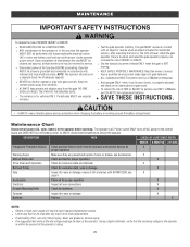
... damage X Gate Inspect for wear or damage; The gate MUST reverse on Have a qualified service person make repairs to the control board and DOES NOT turn off battery power. Operator moving. SAVE THESE INSTRUCTIONS. MAINTENANCE IMPORTANT SAFETY INSTRUCTIONS To reduce the risk of FIRE ...or INJURY to persons use ONLY LiftMaster part 29-NP712 for replacement batteries. Upon completion of maintenance the area MUST be performed by a LiftMaster professional. MUST be properly grounded and connected in the area near the operator MUST...
... damage X Gate Inspect for wear or damage; The gate MUST reverse on Have a qualified service person make repairs to the control board and DOES NOT turn off battery power. Operator moving. SAVE THESE INSTRUCTIONS. MAINTENANCE IMPORTANT SAFETY INSTRUCTIONS To reduce the risk of FIRE ...or INJURY to persons use ONLY LiftMaster part 29-NP712 for replacement batteries. Upon completion of maintenance the area MUST be performed by a LiftMaster professional. MUST be properly grounded and connected in the area near the operator MUST...
Owners Manual - English French
Page 31
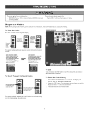
.... The code history has now been reset and the display will show "- -" until a new code occurs. 3. Press and release the STOP button to the control board, it is recommended that you unplug the J15 plug. For continued protection against fire and electrocution: l DISCONNECT power (AC or solar and battery) BEFORE installing...
.... The code history has now been reset and the display will show "- -" until a new code occurs. 3. Press and release the STOP button to the control board, it is recommended that you unplug the J15 plug. For continued protection against fire and electrocution: l DISCONNECT power (AC or solar and battery) BEFORE installing...
Owners Manual - English French
Page 32
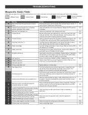
...adjust mounting). one in the close and one in the open connection in the loop. Check wired input on a 12V system. LiftMaster System Installed System Informational External Entrapment Protection Inherent Entrapment Protection Code 31 34 35 36 37 38 40 41 42 43 44 45... for an obstruction, then reprogram the limits. Check wireless edge inputs. If issue continues, replace main control board. Unplug product ID harness then plug back in wireless edge. LiftMaster Plug-in Loop Detector only) Check loop wiring throughout connection. The limits are not. Rundistance can be ...
...adjust mounting). one in the close and one in the open connection in the loop. Check wired input on a 12V system. LiftMaster System Installed System Informational External Entrapment Protection Inherent Entrapment Protection Code 31 34 35 36 37 38 40 41 42 43 44 45... for an obstruction, then reprogram the limits. Check wireless edge inputs. If issue continues, replace main control board. Unplug product ID harness then plug back in wireless edge. LiftMaster Plug-in Loop Detector only) Check loop wiring throughout connection. The limits are not. Rundistance can be ...
Owners Manual - English French
Page 33
...operators, either wired bus or radio. If an obstruction did NOT occur, check alignment, inputs, and wiring on expansion board. Check for proper orientation and resistive end cap connection. If an obstruction did NOT occur, check alignment, inputs, and wiring on ... operator Open input (EYE/EDGE) communication fault from other operator Close input (EYE/EDGE) communication fault (expansion board) Open input (EYE/EDGE) communication fault (expansion board) Non-monitored device detected on Limit and Force Adjustment, and Obstruction Test. Check inputs and communication method between...
...operators, either wired bus or radio. If an obstruction did NOT occur, check alignment, inputs, and wiring on expansion board. Check for proper orientation and resistive end cap connection. If an obstruction did NOT occur, check alignment, inputs, and wiring on ... operator Open input (EYE/EDGE) communication fault from other operator Close input (EYE/EDGE) communication fault (expansion board) Open input (EYE/EDGE) communication fault (expansion board) Non-monitored device detected on Limit and Force Adjustment, and Obstruction Test. Check inputs and communication method between...
Owners Manual - English French
Page 34
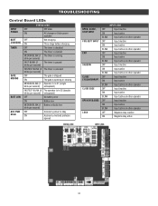
TROUBLESHOOTING Control Board LEDs INPUT OFF POWER ON STATUS LEDS OFF state AC charger or Solar power available BATT OFF CHARGING ON Not charging Three stage battery charging ...
TROUBLESHOOTING Control Board LEDs INPUT OFF POWER ON STATUS LEDS OFF state AC charger or Solar power available BATT OFF CHARGING ON Not charging Three stage battery charging ...
Owners Manual - English French
Page 35
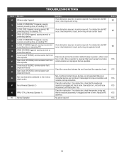
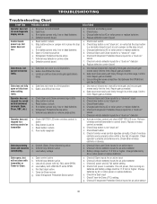
...inputs for an active detector c. No power to a wired control/command (example: Open, Close, SBC, etc.) a. Replace defective control board Control board powers up, but will not close with AC FAIL set too close when setting limits. Gate moves, but cannot set to limit. Gate...control or transmitter a. Gate is active b. Charges batteries by AC or solar power or replace batteries e. c. Operator does not respond to control board b. If on . Charges batteries by AC or solar power or replace batteries d. Check all vehicle detector inputs for a "stuck on batteries...
...inputs for an active detector c. No power to a wired control/command (example: Open, Close, SBC, etc.) a. Replace defective control board Control board powers up, but will not close with AC FAIL set too close when setting limits. Gate moves, but cannot set to limit. Gate...control or transmitter a. Gate is active b. Charges batteries by AC or solar power or replace batteries e. c. Operator does not respond to control board b. If on . Charges batteries by AC or solar power or replace batteries d. Check all vehicle detector inputs for a "stuck on batteries...
Owners Manual - English French
Page 36
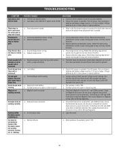
...11.5 Vdc or higher. POSSIBLE CAUSES a. Vehicle loop detector active b. Force adjustment needed . Incorrect Bipart switch setting a. Expansion board setting b. a. Retest that activating edge sensor causes moving gate to stop, and may reverse direction. Replace defective photoelectric sensor. ...b. Normal behavior SOLUTIONS a. a. Check edge sensor wiring. Retest that Solenoid has power (do not power maglock from control board accessory power terminals). a. Check if AC power is available. Check that activating edge sensor causes moving gate to conduct the...
...11.5 Vdc or higher. POSSIBLE CAUSES a. Vehicle loop detector active b. Force adjustment needed . Incorrect Bipart switch setting a. Expansion board setting b. a. Retest that activating edge sensor causes moving gate to stop, and may reverse direction. Replace defective photoelectric sensor. ...b. Normal behavior SOLUTIONS a. a. Check edge sensor wiring. Retest that Solenoid has power (do not power maglock from control board accessory power terminals). a. Check if AC power is available. Check that activating edge sensor causes moving gate to conduct the...
Owners Manual - English French
Page 37
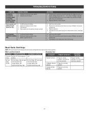
... a. Reduce the accessory power draw by using LiftMaster low power accessories c. Replace batteries d. Use batteries with higher amp hour (AH) rating Dual Gate Settings NOTE: We recommend that all accessory powered devices and measure accessory power voltage (should be 11.5 - 17.5 Vdc). Main control board Accessories FEATURE PRIMARY OPERATOR Timer-to primary...
... a. Reduce the accessory power draw by using LiftMaster low power accessories c. Replace batteries d. Use batteries with higher amp hour (AH) rating Dual Gate Settings NOTE: We recommend that all accessory powered devices and measure accessory power voltage (should be 11.5 - 17.5 Vdc). Main control board Accessories FEATURE PRIMARY OPERATOR Timer-to primary...


