RSL12UL Wiring Diagram
Page 1
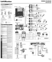
...edge loss of monitoring Check wireless edge inputs. Replace APE assembly. 99 Normal Operation No action required WIRING DIAGRAM Model RSL12UL COAXIAL CABLE ANTENNA Control Board DIAGNOSTICS J25 (see below allowable level. Maglock (Optional) Not provided OR Solenoid Lock (Optional... The operator will blink cycle count Not used J15 Plug on main control board; CODE COLOR KEY: LiftMaster System External Entrapment Protection Installed System Informational Inherent Entrapment Protection CODE MEANING SOLUTION Main control board has experienced an internal Disconnect all power,...
...edge loss of monitoring Check wireless edge inputs. Replace APE assembly. 99 Normal Operation No action required WIRING DIAGRAM Model RSL12UL COAXIAL CABLE ANTENNA Control Board DIAGNOSTICS J25 (see below allowable level. Maglock (Optional) Not provided OR Solenoid Lock (Optional... The operator will blink cycle count Not used J15 Plug on main control board; CODE COLOR KEY: LiftMaster System External Entrapment Protection Installed System Informational Inherent Entrapment Protection CODE MEANING SOLUTION Main control board has experienced an internal Disconnect all power,...

Owners Manual - English French
Page 1
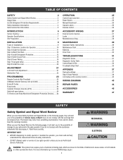
... to 71403. Take a photo of the camera icon including the points ( ). 2. RESIDENTIAL DC VEHICULAR SLIDE GATE OPERATOR INSTALLATION MANUAL Model RSL12UL LiftMaster 300 Windsor Drive Oak Brook, IL 60523 • THIS PRODUCT IS TO BE INSTALLED AND SERVICED BY A TRAINED GATE SYSTEMS TECHNICIAN ONLY. • This model is for use on vehicular passage gates...
... to 71403. Take a photo of the camera icon including the points ( ). 2. RESIDENTIAL DC VEHICULAR SLIDE GATE OPERATOR INSTALLATION MANUAL Model RSL12UL LiftMaster 300 Windsor Drive Oak Brook, IL 60523 • THIS PRODUCT IS TO BE INSTALLED AND SERVICED BY A TRAINED GATE SYSTEMS TECHNICIAN ONLY. • This model is for use on vehicular passage gates...
Owners Manual - English French
Page 2
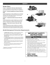
...Rod 15 Step 6 Power Wiring 15 Step 7 Dual gate setup 18 Step 8 Install the cover 20 ADJUSTMENT 21 Limit and Force Adjustment 21 Obstruction Test 22 PROGRAMMING 23 Remote Controls (Not Provided 23 LiftMaster Internet Gateway (not provided 24 Erase All Codes 24 Erase limits 24 Constant Pressure ...WARRANTY 47 SAFETY Safety Symbol and Signal Word Review When you see this Signal Word on the following pages, it will alert you to install, operate or maintain the operator, you must read and fully understand this manual and follow all safety instructions. • DO NOT ...
...Rod 15 Step 6 Power Wiring 15 Step 7 Dual gate setup 18 Step 8 Install the cover 20 ADJUSTMENT 21 Limit and Force Adjustment 21 Obstruction Test 22 PROGRAMMING 23 Remote Controls (Not Provided 23 LiftMaster Internet Gateway (not provided 24 Erase All Codes 24 Erase limits 24 Constant Pressure ...WARRANTY 47 SAFETY Safety Symbol and Signal Word Review When you see this Signal Word on the following pages, it will alert you to install, operate or maintain the operator, you must read and fully understand this manual and follow all safety instructions. • DO NOT ...
Owners Manual - English French
Page 3
... location or building such as one -to adjust and retest the gate operator properly can increase the risk of device shall NOT be installed at each direction; Industrial/Limited Access Vehicular Gate A vehicular gate operator (or system) intended for use in the close direction. Residential...Operator A vehicular gate operator (or system) intended for use in each entrapment zone l This vehicular slide gate operator will operate only after installation of a minimum of the two independent devices * Independent - NO ONE SHOULD CROSS THE PATH OF THE MOVING GATE. Class IV - the...
... location or building such as one -to adjust and retest the gate operator properly can increase the risk of device shall NOT be installed at each direction; Industrial/Limited Access Vehicular Gate A vehicular gate operator (or system) intended for use in the close direction. Residential...Operator A vehicular gate operator (or system) intended for use in each entrapment zone l This vehicular slide gate operator will operate only after installation of a minimum of the two independent devices * Independent - NO ONE SHOULD CROSS THE PATH OF THE MOVING GATE. Class IV - the...

Owners Manual - English French
Page 4
...exercised to mechanical damage. Exception: Emergency access controls only accessible by building structures, natural landscaping or similar obstruction. SAFETY Safety Installation Information 1. A minimum of two (2) WARNING SIGNS shall be located where the risk of l Photoelectric Sensors entrapment or ... the operator to the gate operator for exposed rollers. 12. Specific safety features include: l Edges Sensors (contact) b. Install the gate operator only when: a. c. The pedestrian access opening and closing to promote pedestrian usage. The gate must take...
...exercised to mechanical damage. Exception: Emergency access controls only accessible by building structures, natural landscaping or similar obstruction. SAFETY Safety Installation Information 1. A minimum of two (2) WARNING SIGNS shall be located where the risk of l Photoelectric Sensors entrapment or ... the operator to the gate operator for exposed rollers. 12. Specific safety features include: l Edges Sensors (contact) b. Install the gate operator only when: a. c. The pedestrian access opening and closing to promote pedestrian usage. The gate must take...

Owners Manual - English French
Page 5
...in that portion of the adjacent fence that a pedestrian shall not come in contact with a powered gate operator. Protrusions shall not be installed on any back frame or counterbalance portion of the moving vehicular access gate. The gate panel shall include the entire section of the ... replacement, the new gate shall conform to the designed fully open position or the fully closed positions. Gates shall be designed, constructed and installed to Class IV vehicular horizontal slide gates: All weight bearing exposed rollers 8 feet (2.44 m), or less, above grade shall be guarded or...
...in that portion of the adjacent fence that a pedestrian shall not come in contact with a powered gate operator. Protrusions shall not be installed on any back frame or counterbalance portion of the moving vehicular access gate. The gate panel shall include the entire section of the ... replacement, the new gate shall conform to the designed fully open position or the fully closed positions. Gates shall be designed, constructed and installed to Class IV vehicular horizontal slide gates: All weight bearing exposed rollers 8 feet (2.44 m), or less, above grade shall be guarded or...

Owners Manual - English French
Page 8
...on the inside and outside of operator (refer to stay open when vehicles are recommended. Suggested for low and high voltage. Before installing your Access Control Device(s) be sure to complete a site survey and determine the best device for your gate application. INTRODUCTION Site ... in your site needs. 8 Vehicle loops are not required but are obstructing the gate path. Conduit and Concrete Pad Trench and install conduit. Additional Accessories The vehicle loops allow the gate to specifications). Gate must fit specifications of the property, where easily visible. Before...
...on the inside and outside of operator (refer to stay open when vehicles are recommended. Suggested for low and high voltage. Before installing your Access Control Device(s) be sure to complete a site survey and determine the best device for your gate application. INTRODUCTION Site ... in your site needs. 8 Vehicle loops are not required but are obstructing the gate path. Conduit and Concrete Pad Trench and install conduit. Additional Accessories The vehicle loops allow the gate to specifications). Gate must fit specifications of the property, where easily visible. Before...
Owners Manual - English French
Page 9
Types of Installations Standard Installation Rear Installation 9 INSTALLATION l To AVOID damaging gas, power or other underground utility lines, l ALWAYS wear protective gloves and eye protection when changing contact underground utility locating companies BEFORE digging more the battery or working around the battery compartment. than 18 inches (46 cm) deep.
Types of Installations Standard Installation Rear Installation 9 INSTALLATION l To AVOID damaging gas, power or other underground utility lines, l ALWAYS wear protective gloves and eye protection when changing contact underground utility locating companies BEFORE digging more the battery or working around the battery compartment. than 18 inches (46 cm) deep.

Owners Manual - English French
Page 10
Install the electrical conduit. 3. Rear Installation 1. Pour a concrete pad (reinforced concrete is recommended). Install the electrical conduit. 3. The gate operator should be installed near the front roller of the gate in the OPEN position. Lay out the concrete pad. 2. Pour a concrete pad (reinforced concrete is recommended). 10 The gate operator should be installed near the back of the gate. INSTALLATION Step 1 Determine Location for Operator Check the national and local building codes before installation. Lay out the concrete pad. 2. Standard Installation 1.
Install the electrical conduit. 3. Rear Installation 1. Pour a concrete pad (reinforced concrete is recommended). Install the electrical conduit. 3. The gate operator should be installed near the front roller of the gate in the OPEN position. Lay out the concrete pad. 2. Pour a concrete pad (reinforced concrete is recommended). 10 The gate operator should be installed near the back of the gate. INSTALLATION Step 1 Determine Location for Operator Check the national and local building codes before installation. Lay out the concrete pad. 2. Standard Installation 1.

Owners Manual - English French
Page 11
The space between the gate and the output sprocket must be installed near the front roller of the gate or near the back of 4 inches (10.2 cm). 11 The gate operator should be a minimum of the gate (in the OPEN position). INSTALLATION Step 2 Install the Operator Attach the operator to the concrete pad with appropriate fasteners.
The space between the gate and the output sprocket must be installed near the front roller of the gate or near the back of 4 inches (10.2 cm). 11 The gate operator should be a minimum of the gate (in the OPEN position). INSTALLATION Step 2 Install the Operator Attach the operator to the concrete pad with appropriate fasteners.

Owners Manual - English French
Page 12
... bracket so the chain will be level with the idler pulley and parallel to the ground. Weld the bottom bracket in this position. 3. NOTE: This installation will be level with the bottom idler pulley and parallel to the ground. NOTE: The chain should not be too tight or have no more... Route the chain through the operator. 4. Weld the front bracket in the operator. 2. Chain should have excessive slack. Weld the upper bracket in this position. 2. INSTALLATION Step 3 Attach the Chain Standard Installation DO NOT run the operator until instructed. 1.
... bracket so the chain will be level with the idler pulley and parallel to the ground. Weld the bottom bracket in this position. 3. NOTE: This installation will be level with the bottom idler pulley and parallel to the ground. NOTE: The chain should not be too tight or have no more... Route the chain through the operator. 4. Weld the front bracket in the operator. 2. Chain should have excessive slack. Weld the upper bracket in this position. 2. INSTALLATION Step 3 Attach the Chain Standard Installation DO NOT run the operator until instructed. 1.

Owners Manual - English French
Page 13
l Locate entrapment protection devices to 6 ft. (1.8 m) above grade. l LiftMaster monitored external entrapment protection devices MUST be installed to ensure that increases the risk of injury. SLIDE GATE ENTRAPMENT ZONE: An entrapment zone exists if ...in the open and close gate cycles. l Locate entrapment protection devices to function; INSTALLATION To prevent SERIOUS INJURY or DEATH from a moving gate. l Entrapment protection devices MUST be used with LiftMaster operators to the manual provided with an external monitored entrapment protection device, protecting both the...
l Locate entrapment protection devices to 6 ft. (1.8 m) above grade. l LiftMaster monitored external entrapment protection devices MUST be installed to ensure that increases the risk of injury. SLIDE GATE ENTRAPMENT ZONE: An entrapment zone exists if ...in the open and close gate cycles. l Locate entrapment protection devices to function; INSTALLATION To prevent SERIOUS INJURY or DEATH from a moving gate. l Entrapment protection devices MUST be used with LiftMaster operators to the manual provided with an external monitored entrapment protection device, protecting both the...
Owners Manual - English French
Page 14
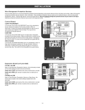
INSTALLATION Wire Entrapment Protection Devices There are for monitored devices, which include pulsed photoelectric sensors, resistive edge sensors, and pulsed edge sensors. Additional entrapment protection devices ...
INSTALLATION Wire Entrapment Protection Devices There are for monitored devices, which include pulsed photoelectric sensors, resistive edge sensors, and pulsed edge sensors. Additional entrapment protection devices ...
Owners Manual - English French
Page 15
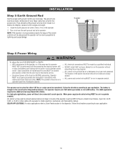
... Step 6 Power Wiring To reduce the risk of maintenance the area MUST be performed until disconnecting the electrical power (AC l DO NOT install ANY wiring or attempt to the operator. MUST NOT be cleared and secured, at the fuse box BEFORE proceeding. Operator labeled. separate fused... operator. Never splice two wires for your application. MUST be more susceptible to Solar Panels section in accordance with a single wire length. 1. INSTALLATION Step 5 Earth Ground Rod Use the proper earth ground rod for the ground wire. The operator can be on a l ALL power and ...
... Step 6 Power Wiring To reduce the risk of maintenance the area MUST be performed until disconnecting the electrical power (AC l DO NOT install ANY wiring or attempt to the operator. MUST NOT be cleared and secured, at the fuse box BEFORE proceeding. Operator labeled. separate fused... operator. Never splice two wires for your application. MUST be more susceptible to Solar Panels section in accordance with a single wire length. 1. INSTALLATION Step 5 Earth Ground Rod Use the proper earth ground rod for the ground wire. The operator can be on a l ALL power and ...
Owners Manual - English French
Page 16
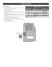
... feet (351 m) 400 feet (122 m) 12 1850 feet (564 m) 600 feet (183 m) 10 2950 feet (899 m) 1,000 feet (305 m) NOTE: Use copper conductors ONLY. 16 INSTALLATION Power wiring 1. Run the AC power wires to the operator. Ensure the wires are not pinched. 10. Unplug the transformer. 4. Run the AC power wires...
... feet (351 m) 400 feet (122 m) 12 1850 feet (564 m) 600 feet (183 m) 10 2950 feet (899 m) 1,000 feet (305 m) NOTE: Use copper conductors ONLY. 16 INSTALLATION Power wiring 1. Run the AC power wires to the operator. Ensure the wires are not pinched. 10. Unplug the transformer. 4. Run the AC power wires...
Owners Manual - English French
Page 17
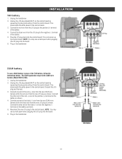
... and harness. 3. Connect the other end of the 7AH battery, follow the instructions below. Plug in place of the red (+) wire to the control board. 3. INSTALLATION 7AH battery 1. Connect one end of the black (-) wire to the negative (-) terminal on the battery as shown. Connect the red wire from the new...
... and harness. 3. Connect the other end of the 7AH battery, follow the instructions below. Plug in place of the red (+) wire to the control board. 3. INSTALLATION 7AH battery 1. Connect one end of the black (-) wire to the negative (-) terminal on the battery as shown. Connect the red wire from the new...
Owners Manual - English French
Page 18
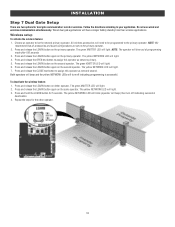
... green XMITTER LED will light. 4. The yellow NETWORK LED will light. 2. Press and release the CLOSE test button to assign this operator as network primary. 5. INSTALLATION Step 7 Dual Gate Setup There are set on the primary operator. Follow the directions according to be programmed to the primary operator. Wireless setup To...
... green XMITTER LED will light. 4. The yellow NETWORK LED will light. 2. Press and release the CLOSE test button to assign this operator as network primary. 5. INSTALLATION Step 7 Dual Gate Setup There are set on the primary operator. Follow the directions according to be programmed to the primary operator. Wireless setup To...
Owners Manual - English French
Page 19
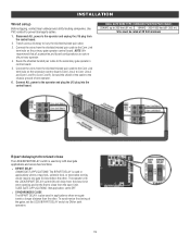
... cable to the Com Link terminals on the primary gate operator control board. Connect the wires from the open limit. Connect ALL power to cables. 1. INSTALLATION Wired setup Before digging, contact local underground utility locating companies. To synchronize the closing of one gate travels a longer distance than the other . Use PVC...
... cable to the Com Link terminals on the primary gate operator control board. Connect the wires from the open limit. Connect ALL power to cables. 1. INSTALLATION Wired setup Before digging, contact local underground utility locating companies. To synchronize the closing of one gate travels a longer distance than the other . Use PVC...

Owners Manual - English French
Page 20
Slide the cover over the operator. 2. The basic installation is complete. 20 Align the hole in the cover with the threaded hole in the operator's chassis and secure the cover with the provided 5/16-18 screw. INSTALLATION Step 8 Install the Cover 1.
Slide the cover over the operator. 2. The basic installation is complete. 20 Align the hole in the cover with the threaded hole in the operator's chassis and secure the cover with the provided 5/16-18 screw. INSTALLATION Step 8 Install the Cover 1.
Owners Manual - English French
Page 21
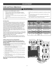
...remote control (refer to Limit Setup with electronic controls to make travel limits) is not set MODE ON ON LIMIT SETTING Limits are installed. Initial Limits and Force Adjustment For dual gate applications the limits will have been set and the required entrapment protection devices are set... limit and force adjustments easy. ADJUSTMENT Limit and Force Adjustment To reduce the risk of SEVERE INJURY or DEATH: l Without a properly installed safety reversal system, persons (particularly small children) could be set using the REVERSAL FORCE dial on the control board (refer to Fine Tune...
...remote control (refer to Limit Setup with electronic controls to make travel limits) is not set MODE ON ON LIMIT SETTING Limits are installed. Initial Limits and Force Adjustment For dual gate applications the limits will have been set and the required entrapment protection devices are set... limit and force adjustments easy. ADJUSTMENT Limit and Force Adjustment To reduce the risk of SEVERE INJURY or DEATH: l Without a properly installed safety reversal system, persons (particularly small children) could be set using the REVERSAL FORCE dial on the control board (refer to Fine Tune...


