
Solar Gate Access System Daily Cycle Chart Manual
Page 1
...zone. NUMBER OF CYCLES PER DAY (SOLAR-DUAL SWING GATE) Swing Gate ACCESSORY ZONE 1 Installation POWER (6 Hrs (12 ft. 800 lb. Snow, performance minimizing power consumption at all other times. The LA500 is not supported in the given and standby ... 66 NOTE: 40W would be cleaned regularly to ensure proper operation. and charge rate. LA500 not supported/available in an open area clear LAipnon4wo1ve2ar twiSvheoePnloanwereeGrdMeadatnmeaogAsetcmfocerneot spSeysrsatSteinmygstaotegdaemtleivewDrhaileily Cycle Chart of obstructions and shading for the entire day. ...
...zone. NUMBER OF CYCLES PER DAY (SOLAR-DUAL SWING GATE) Swing Gate ACCESSORY ZONE 1 Installation POWER (6 Hrs (12 ft. 800 lb. Snow, performance minimizing power consumption at all other times. The LA500 is not supported in the given and standby ... 66 NOTE: 40W would be cleaned regularly to ensure proper operation. and charge rate. LA500 not supported/available in an open area clear LAipnon4wo1ve2ar twiSvheoePnloanwereeGrdMeadatnmeaogAsetcmfocerneot spSeysrsatSteinmygstaotegdaemtleivewDrhaileily Cycle Chart of obstructions and shading for the entire day. ...
LA500 Manual
Page 11
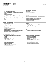
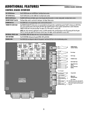
... Detector Connectors (Model LOOPDETLM Loop Detector) - SHADOW - GATE MOVING: ON with Fail Open/Fail Close selection • Quick-Close ON/OFF selection switch • AC Fail Open/Battery selection switch • Low Battery Open/Close selection switch • Anti-Tail ON/OFF selection ...Electronic limit adjustment and control from close limit switch - OPEN, CLOSE, or STOP: accessory connection and on-board button - POWER: ON with up to -Close (TTC) • Maximum Run Timer • Bipart Delay switch (dual gate applications) • Feedback and Diagnostic LEDs • ...
... Detector Connectors (Model LOOPDETLM Loop Detector) - SHADOW - GATE MOVING: ON with Fail Open/Fail Close selection • Quick-Close ON/OFF selection switch • AC Fail Open/Battery selection switch • Low Battery Open/Close selection switch • Anti-Tail ON/OFF selection ...Electronic limit adjustment and control from close limit switch - OPEN, CLOSE, or STOP: accessory connection and on-board button - POWER: ON with up to -Close (TTC) • Maximum Run Timer • Bipart Delay switch (dual gate applications) • Feedback and Diagnostic LEDs • ...
LA500 Manual
Page 13
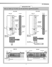
... Steel Plate for Maximum Strength. Water Tight Conduit (Not provided) Earth Ground Rod Control Box Primary Operator ! DUAL GATE Secondary Operator Junction Box ! The installation steps in this manual will show a typical Pull-to-Open application. Water Tight Conduit (Not provided) Earth Ground Rod 11 Shielded low voltage wires. INSTALLATION TYPES Identify your...
... Steel Plate for Maximum Strength. Water Tight Conduit (Not provided) Earth Ground Rod Control Box Primary Operator ! DUAL GATE Secondary Operator Junction Box ! The installation steps in this manual will show a typical Pull-to-Open application. Water Tight Conduit (Not provided) Earth Ground Rod 11 Shielded low voltage wires. INSTALLATION TYPES Identify your...
LA500 Manual
Page 17
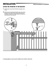
Post Bracket ATTACH THE OPERATOR TO THE BRACKETS Gate Bracket For dual gate applications, repeat the previous installation steps to overtighten. Make sure the trolley does not reach the fully open or fully closed position. Tighten the nut until it reaches the bottom of the gate bracket, then turn the nut a half turn, making sure not... OPERATOR TO THE BRACKETS 1 Attach the operator to the post bracket with the bolt, mounting plate, and nut as shown. 2 Attach the operator to the gate bracket with the bolt, washer, and nut as shown.
Post Bracket ATTACH THE OPERATOR TO THE BRACKETS Gate Bracket For dual gate applications, repeat the previous installation steps to overtighten. Make sure the trolley does not reach the fully open or fully closed position. Tighten the nut until it reaches the bottom of the gate bracket, then turn the nut a half turn, making sure not... OPERATOR TO THE BRACKETS 1 Attach the operator to the post bracket with the bolt, mounting plate, and nut as shown. 2 Attach the operator to the gate bracket with the bolt, washer, and nut as shown.
LA500 Manual
Page 22
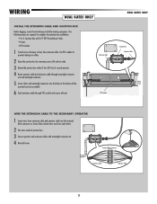
... and operator cable into the holes in the bottom of junction box. 3 Secure operator and extension cables with nut. WIRING DUAL GATES ONLY INSTALL THE EXTENSION CABLE AND JUNCTION BOX Before digging, contact local underground utility locating companies. Use PVC conduit to prevent ...installation: • 4 x 4 Junction Box with 3/4" NPT threaded port holes • Screws • PVC Conduit 1 Trench across driveway to cables. 2 Open the junction box by removing screws (4) and set aside. 3 Mount the junction box within 3 feet (0.9 m) of second operator. 4 Route operator cable and...
... and operator cable into the holes in the bottom of junction box. 3 Secure operator and extension cables with nut. WIRING DUAL GATES ONLY INSTALL THE EXTENSION CABLE AND JUNCTION BOX Before digging, contact local underground utility locating companies. Use PVC conduit to prevent ...installation: • 4 x 4 Junction Box with 3/4" NPT threaded port holes • Screws • PVC Conduit 1 Trench across driveway to cables. 2 Open the junction box by removing screws (4) and set aside. 3 Mount the junction box within 3 feet (0.9 m) of second operator. 4 Route operator cable and...
LA500 Manual
Page 23
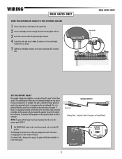
... THE BIPART DELAY Occasionally in the bottom of the gate. Connect to Gate 1 connections on the control board. WIRING DUAL GATES ONLY DUAL GATES ONLY WIRE THE EXTENSION CABLE TO THE CONTROL BOARD 1 Choose a knockout in dual gate installations, one gate or if using a solenoid lock, for the control... shows a dual gate configuration with the lock attached to it is no appropriate location on that the control box be set to Gate 2 connector on the same side as shown. 5 Tighten the watertight connector nut to secure extension cable to the Gate 1 connector. S T OPEN SET CLOSE OFF...
... THE BIPART DELAY Occasionally in the bottom of the gate. Connect to Gate 1 connections on the control board. WIRING DUAL GATES ONLY DUAL GATES ONLY WIRE THE EXTENSION CABLE TO THE CONTROL BOARD 1 Choose a knockout in dual gate installations, one gate or if using a solenoid lock, for the control... shows a dual gate configuration with the lock attached to it is no appropriate location on that the control box be set to Gate 2 connector on the same side as shown. 5 Tighten the watertight connector nut to secure extension cable to the Gate 1 connector. S T OPEN SET CLOSE OFF...
LA500 Manual
Page 25
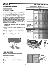
The solar panel(s) must be located in an open area clear of two 10W solar panels in northern climates where temperatures ...NOT AVAILABLE 3 1 2 NOT AVAILABLE 1 1 CONNECT BATTERIES The batteries are recommended (for areas that reach below -4˚F. We recommend LiftMaster low power draw accessories to minimize power draw, refer to the operator. 23 Battery Connector J15 Plug N.O. COM J15 + BATT - +... 125 42 51 148 193 92 119 37 45 145 190 90 117 35 43 135 179 80 106 25 33 Dual Gates 20W SOLAR PANEL NOTE: 20W would be two 10W (12V) panels in series. ✔ ✔ ✔ ...
The solar panel(s) must be located in an open area clear of two 10W solar panels in northern climates where temperatures ...NOT AVAILABLE 3 1 2 NOT AVAILABLE 1 1 CONNECT BATTERIES The batteries are recommended (for areas that reach below -4˚F. We recommend LiftMaster low power draw accessories to minimize power draw, refer to the operator. 23 Battery Connector J15 Plug N.O. COM J15 + BATT - +... 125 42 51 148 193 92 119 37 45 145 190 90 117 35 43 135 179 80 106 25 33 Dual Gates 20W SOLAR PANEL NOTE: 20W would be two 10W (12V) panels in series. ✔ ✔ ✔ ...
LA500 Manual
Page 27
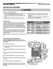
... • After ANY adjustments are not set properly the operator will automatically exit limit setting mode. ! INITIAL LIMITS AND FORCE ADJUSTMENT For dual gate applications the limits will have been set . When limits are set . NOTE: The Test Buttons on the control board will not work ... ED BR RN WT E BLU ED SOL R / CHARG R + ROUND MOVE GATE SET OPEN SET CLOSE B DEL US OPEN limit PRESS & RELEASE TO BEG OFF 6 P REL TO BE LIMIT SETUP 1 5 2 GAT INPU DUAL GATES: Set the GATE switch to make travel limits) is being set for each operator. INTRODUCTION Your operator...
... • After ANY adjustments are not set properly the operator will automatically exit limit setting mode. ! INITIAL LIMITS AND FORCE ADJUSTMENT For dual gate applications the limits will have been set . When limits are set . NOTE: The Test Buttons on the control board will not work ... ED BR RN WT E BLU ED SOL R / CHARG R + ROUND MOVE GATE SET OPEN SET CLOSE B DEL US OPEN limit PRESS & RELEASE TO BEG OFF 6 P REL TO BE LIMIT SETUP 1 5 2 GAT INPU DUAL GATES: Set the GATE switch to make travel limits) is being set for each operator. INTRODUCTION Your operator...
LA500 Manual
Page 32
...codes for dual gates. Power K Switched ON with expansion board connected. BOARD BR GRN WT YE BLU RED BR GRN WT YE BLU RED SOLAR / CHARGER + GROUND ID RESET ALARM 30 ADDITIONAL FEATURES CONTROL BOARD OVERVIEW CONTROL BOARD OVERVIEW SET OPEN Button SET CLOSE Button MOVE GATE Button ...-CLOSE (TTC) dial can be set to the TTC expiring will operate the gate (OPEN, STOP and CLOSE). If the TTC is set to save L battery power if expansion board disconnected. OPEN CLOSE STOP SET OPEN SET CLOSE MOVE GATE OFF ON PRESS & RELEASE TO BEGIN LIMIT SETUP 1 2 (SECONDS) 10...
...codes for dual gates. Power K Switched ON with expansion board connected. BOARD BR GRN WT YE BLU RED BR GRN WT YE BLU RED SOLAR / CHARGER + GROUND ID RESET ALARM 30 ADDITIONAL FEATURES CONTROL BOARD OVERVIEW CONTROL BOARD OVERVIEW SET OPEN Button SET CLOSE Button MOVE GATE Button ...-CLOSE (TTC) dial can be set to the TTC expiring will operate the gate (OPEN, STOP and CLOSE). If the TTC is set to save L battery power if expansion board disconnected. OPEN CLOSE STOP SET OPEN SET CLOSE MOVE GATE OFF ON PRESS & RELEASE TO BEGIN LIMIT SETUP 1 2 (SECONDS) 10...
LA500 Manual
Page 36
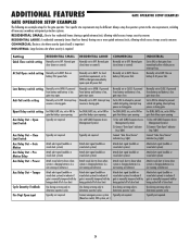
... - If powered from battery and battery is low, gate stays close. For DUAL-GATE site, set to ON for gate that delays upon opening 1) Use with SAMS (Sequence Access Management System) 2) Connect "Gate Open" indicator (e.g. For DUAL-GATE site, set to ON for gate that delays upon opening Typically not required. For DUAL-GATE site, set to determine operator cycles Typically not required...
... - If powered from battery and battery is low, gate stays close. For DUAL-GATE site, set to ON for gate that delays upon opening 1) Use with SAMS (Sequence Access Management System) 2) Connect "Gate Open" indicator (e.g. For DUAL-GATE site, set to ON for gate that delays upon opening Typically not required. For DUAL-GATE site, set to determine operator cycles Typically not required...
LA500 Manual
Page 37
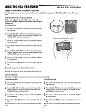
... AND FORCE ADJUSTMENT For dual gate applications the limits will have already been set the operator will exit the limit setting mode after resetting each operator. The gate can be attached to the Programming section. The gate MUST be jogged back and forth using the OPEN and CLOSE buttons on .... 5 Press and hold the CLOSE button on the remote control again to set the close limit. 8 Cycle the gate open limit. The gate can be set for each limit. SET OPEN SET CLOSE B D FF SET OPEN SET CLOSE ER WO K MO E G TE STATUS R ES OB G LMT S C ND ) 10 2 5 OF N UT POW R TM R ...
... AND FORCE ADJUSTMENT For dual gate applications the limits will have already been set the operator will exit the limit setting mode after resetting each operator. The gate can be attached to the Programming section. The gate MUST be jogged back and forth using the OPEN and CLOSE buttons on .... 5 Press and hold the CLOSE button on the remote control again to set the close limit. 8 Cycle the gate open limit. The gate can be set for each limit. SET OPEN SET CLOSE B D FF SET OPEN SET CLOSE ER WO K MO E G TE STATUS R ES OB G LMT S C ND ) 10 2 5 OF N UT POW R TM R ...
LA500 Manual
Page 42
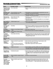
... wiring b) Incorrect input wiring to stop, and may reverse direction. a) Main control board is not commanding the other operator. a) Check edge sensor wiring. On dual-gate system, incorrect gate opens first or closes first. Charge batteries by AC or solar power or replace batteries a) Check operator-to -Operator wireless learning a) Incorrect Bipart switch setting...
... wiring b) Incorrect input wiring to stop, and may reverse direction. a) Main control board is not commanding the other operator. a) Check edge sensor wiring. On dual-gate system, incorrect gate opens first or closes first. Charge batteries by AC or solar power or replace batteries a) Check operator-to -Operator wireless learning a) Incorrect Bipart switch setting...


