LA412 Manual
Page 2
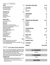
...Gate Mounting Options Manual Release Determine the Position of the Pull-to-Open Bracket Determine the Position of the "Optional" Push-to-Open Bracket Assemble Gate Post Bracket (Pull-to-Open) Attach Brackets to Gate Operator Determine Mounting Location Measuring and Marking for the Gate Bracket Position Gate Operator on Gate Test Gate... 19 WIRING 20-24 Connect the Gate Operator (Gate 1) to the Control Box 20 Set the Lock/Bipart Delay (Model LA412-S Only) 21 Connect the Gate Operator (Gate 2) to the Control Box (Model LA412-S Only) 22 Junction Box (Model LA412-S Only) 23-24 SOLAR PANEL ...
...Gate Mounting Options Manual Release Determine the Position of the Pull-to-Open Bracket Determine the Position of the "Optional" Push-to-Open Bracket Assemble Gate Post Bracket (Pull-to-Open) Attach Brackets to Gate Operator Determine Mounting Location Measuring and Marking for the Gate Bracket Position Gate Operator on Gate Test Gate... 19 WIRING 20-24 Connect the Gate Operator (Gate 1) to the Control Box 20 Set the Lock/Bipart Delay (Model LA412-S Only) 21 Connect the Gate Operator (Gate 2) to the Control Box (Model LA412-S Only) 22 Junction Box (Model LA412-S Only) 23-24 SOLAR PANEL ...
LA412 Manual
Page 3
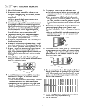
...not come in the area of the gate. 3. Swinging gates shall not open into every installation. The pedestrian access shall be supplied with two safety warning placards. b. Never mount any pedestrian gate. SAVE THE INSTRUCTIONS. 2 Class I vehicular swing gates. All exposed pinch points must be...photoelectric sensors), see product manual on any device that communication between the sensor and the gate operator is still moving gate: • A hard wired control device shall be installed on or ride the gate during normal operation. Install the gate operator only when the ...
...not come in the area of the gate. 3. Swinging gates shall not open into every installation. The pedestrian access shall be supplied with two safety warning placards. b. Never mount any pedestrian gate. SAVE THE INSTRUCTIONS. 2 Class I vehicular swing gates. All exposed pinch points must be...photoelectric sensors), see product manual on any device that communication between the sensor and the gate operator is still moving gate: • A hard wired control device shall be installed on or ride the gate during normal operation. Install the gate operator only when the ...
LA412 Manual
Page 4
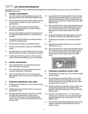
...and installed so as a wall, pillar or column, and a swing gate when in the open position shall not be less than 16 inches (406 mm), refer to ASTM F2200 for panel types. 1.5 An existing gate latch shall be disabled when a manually operated gate is to be automated shall be upgraded to conform to the... provisions of the gate where such stops shall horizontally or ...
...and installed so as a wall, pillar or column, and a swing gate when in the open position shall not be less than 16 inches (406 mm), refer to ASTM F2200 for panel types. 1.5 An existing gate latch shall be disabled when a manually operated gate is to be automated shall be upgraded to conform to the... provisions of the gate where such stops shall horizontally or ...
LA412 Manual
Page 12
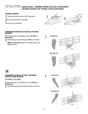
... will damage the operator. 1 LEFT-HAND GATE RIGHT-HAND GATE Release Lever OR DETERMINE POSITION OF THE "OPTIONAL" PUSH-TO-OPEN BRACKET (NOT PROVIDED. NOTE: If the Pull-To-Open bracket is now in manual mode. SEE ACCESSORIES) The Push-To-Open bracket can be assembled to work on a... on a Left-Hand or a Right-Hand gate. 1 Review the gate types and select the type of installation you will require. INSTALLATION » MANUAL RELEASE + DETERMINE POSITION OF THE PULL-TO-OPEN BRACKET + DETERMINE POSITION OF THE "OPTIONAL" PUSH-TO-OPEN BRACKET MANUAL RELEASE 1 Insert the key into the lock...
... will damage the operator. 1 LEFT-HAND GATE RIGHT-HAND GATE Release Lever OR DETERMINE POSITION OF THE "OPTIONAL" PUSH-TO-OPEN BRACKET (NOT PROVIDED. NOTE: If the Pull-To-Open bracket is now in manual mode. SEE ACCESSORIES) The Push-To-Open bracket can be assembled to work on a... on a Left-Hand or a Right-Hand gate. 1 Review the gate types and select the type of installation you will require. INSTALLATION » MANUAL RELEASE + DETERMINE POSITION OF THE PULL-TO-OPEN BRACKET + DETERMINE POSITION OF THE "OPTIONAL" PUSH-TO-OPEN BRACKET MANUAL RELEASE 1 Insert the key into the lock...
LA412 Manual
Page 14
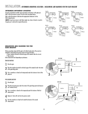
... dimensions for determining the proper location of the post brackets: • Paper template (Located on the back page of this manual) under the center of the gate hinge point. 3 Use a screwdriver or dowel rod to temporarily mark the location in the fully closed position. There are ...two methods for the Pull-To-Open bracket. TEMPLATE METHOD 1 Close the gate. 2 Place the template (provided on page 10 for the ideal mounting location. Either method will work depending on the gate post. NOTE: It may be cut out.) • Tape measure....
... dimensions for determining the proper location of the post brackets: • Paper template (Located on the back page of this manual) under the center of the gate hinge point. 3 Use a screwdriver or dowel rod to temporarily mark the location in the fully closed position. There are ...two methods for the Pull-To-Open bracket. TEMPLATE METHOD 1 Close the gate. 2 Place the template (provided on page 10 for the ideal mounting location. Either method will work depending on the gate post. NOTE: It may be cut out.) • Tape measure....
LA412 Manual
Page 16
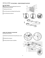
... Lock Washers 15 2 Carriage Bolts Welder (Optional) INSTALLATION » TEST GATE TRAVEL + SECURE POST BRACKET TO GATE POST TEST GATE TRAVEL NOTE: If gate does not open and close completely adjust the position of the 1 gate bracket and mark new mounting holes. 1 Manually open and close the gate. 2 Ensure that the operator does not bind against the pull-to...
... Lock Washers 15 2 Carriage Bolts Welder (Optional) INSTALLATION » TEST GATE TRAVEL + SECURE POST BRACKET TO GATE POST TEST GATE TRAVEL NOTE: If gate does not open and close completely adjust the position of the 1 gate bracket and mark new mounting holes. 1 Manually open and close the gate. 2 Ensure that the operator does not bind against the pull-to...
LA412 Manual
Page 17
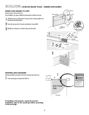
... warning signs to the gate with cable ties. Reinforcement Area 3 Manually move at any time without prior warning. Fence Gate Post 1 Gate Gate Travel Path If installing a 2nd operator, repeat the previous installation steps for the second gate before proceeding to the gate using hardware (not provided...Some installations may move the gate to verify that are large enough for vehicles only Pedestrians must be level. Gate may require additional reinforcement be installed on the gate. 1 Drill holes in gate (or reinforcement, if necessary) that it opens and closes fully. 1 Operator...
... warning signs to the gate with cable ties. Reinforcement Area 3 Manually move at any time without prior warning. Fence Gate Post 1 Gate Gate Travel Path If installing a 2nd operator, repeat the previous installation steps for the second gate before proceeding to the gate using hardware (not provided...Some installations may move the gate to verify that are large enough for vehicles only Pedestrians must be level. Gate may require additional reinforcement be installed on the gate. 1 Drill holes in gate (or reinforcement, if necessary) that it opens and closes fully. 1 Operator...
LA412 Manual
Page 36
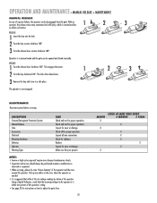
... disengaged from the gate. ENGAGE 1 Turn the release lever clockwise 180°. OPERATION AND MAINTENANCE » MANUAL RELEASE + MAINTENANCE MANUAL RELEASE In case of a power failure, the operator can be opened and closed manually. DESCRIPTION External Entrapment Protection System Manual Release Gate Accessories Electrical Mounting Hardware... the release lever counter-clockwise 180°. Clean the operator as needed. • It is in manual mode and the gate can be performed anytime a malfunction is within ten percent of the operator and the area around the operator.
... disengaged from the gate. ENGAGE 1 Turn the release lever clockwise 180°. OPERATION AND MAINTENANCE » MANUAL RELEASE + MAINTENANCE MANUAL RELEASE In case of a power failure, the operator can be opened and closed manually. DESCRIPTION External Entrapment Protection System Manual Release Gate Accessories Electrical Mounting Hardware... the release lever counter-clockwise 180°. Clean the operator as needed. • It is in manual mode and the gate can be performed anytime a malfunction is within ten percent of the operator and the area around the operator.
LA412 Manual
Page 43
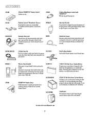
... battery is designed to prevent disconnection of the gate operator and the gate while providing a means to open the gate in this manual. CLOSE Homeowner can open . LA12VXFMR Push-To-Open Bracket: Used to aOPlElNow the gate operator to push the gate open gate from inside the home using a 4-digit code... case of reduced sunlight and colder weather. OPEN CLOSE 50-19503 Wireless Gate Doorbell: Allows guests to the gate operator. For increased operating cycles during periods of power failure. To order visit www.liftmaster.com 42 OPEN CLOSE Do not use with 7 AH battery...
... battery is designed to prevent disconnection of the gate operator and the gate while providing a means to open the gate in this manual. CLOSE Homeowner can open . LA12VXFMR Push-To-Open Bracket: Used to aOPlElNow the gate operator to push the gate open gate from inside the home using a 4-digit code... case of reduced sunlight and colder weather. OPEN CLOSE 50-19503 Wireless Gate Doorbell: Allows guests to the gate operator. For increased operating cycles during periods of power failure. To order visit www.liftmaster.com 42 OPEN CLOSE Do not use with 7 AH battery...


