
LA400DC Sell Sheet Manual
Page 2
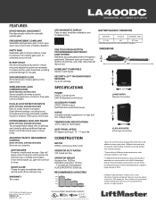
...LiftMaster® Internet Gateway Accessory functionality is 300 ft. BATTERY BACKUP OPERATION BATTERY CYCLES STANDBY TIME 2-7 AH 400 97 Days Battery Backup operation 400 cycles (10ft/850 lb. Maintains open or close . ACCESSORY POWER 24VDC 500mA output Switched and unswitched power. OPERATOR WEIGHT Actuator Arm... seconds. LA400CONTDC Standard Control Box XLSOLARCONTDC Extra Large Control Box CONSTRUCTION MOTOR 24VDC continuous-duty motor. LA400DC RESIDENTIAL DC LINEAR ACTUATOR FEATURES KEYED MANUAL DISCONNECT Provides simple method to -read, simplifies installation and ...
...LiftMaster® Internet Gateway Accessory functionality is 300 ft. BATTERY BACKUP OPERATION BATTERY CYCLES STANDBY TIME 2-7 AH 400 97 Days Battery Backup operation 400 cycles (10ft/850 lb. Maintains open or close . ACCESSORY POWER 24VDC 500mA output Switched and unswitched power. OPERATOR WEIGHT Actuator Arm... seconds. LA400CONTDC Standard Control Box XLSOLARCONTDC Extra Large Control Box CONSTRUCTION MOTOR 24VDC continuous-duty motor. LA400DC RESIDENTIAL DC LINEAR ACTUATOR FEATURES KEYED MANUAL DISCONNECT Provides simple method to -read, simplifies installation and ...
LA400DC Owner's Manual
Page 3
... WIRING 22 FINISH INSTALL 23 ADJUSTMENT 23 LIMIT AND FORCE ADJUSTMENT 23 OBSTRUCTION TEST 25 PROGRAMMING 26 REMOTE CONTROLS (NOT PROVIDED 26 LIFTMASTER INTERNET GATEWAY (NOT PROVIDED 27 ERASE ALL CODES 27 ERASE LIMITS 27 TO REMOVE AND ERASE MONITORED ENTRAPMENT PROTECTION DEVICES 27 OPERATION ... 41 BRACKET TYPES 41 SOLAR PANEL(S 42 LIMIT SETUP WITH A REMOTE CONTROL 47 REPAIR PARTS 48 CONTROL BOX 48 GATE OPERATOR ARM 48 WIRING DIAGRAM 49 STANDARD CONTROL BOX 49 ACCESSORIES 50 WARRANTY 51 TEMPLATE FOR POST BRACKET MOUNTING 52 SAFETY SAFETY SYMBOL AND SIGNAL...
... WIRING 22 FINISH INSTALL 23 ADJUSTMENT 23 LIMIT AND FORCE ADJUSTMENT 23 OBSTRUCTION TEST 25 PROGRAMMING 26 REMOTE CONTROLS (NOT PROVIDED 26 LIFTMASTER INTERNET GATEWAY (NOT PROVIDED 27 ERASE ALL CODES 27 ERASE LIMITS 27 TO REMOVE AND ERASE MONITORED ENTRAPMENT PROTECTION DEVICES 27 OPERATION ... 41 BRACKET TYPES 41 SOLAR PANEL(S 42 LIMIT SETUP WITH A REMOTE CONTROL 47 REPAIR PARTS 48 CONTROL BOX 48 GATE OPERATOR ARM 48 WIRING DIAGRAM 49 STANDARD CONTROL BOX 49 ACCESSORIES 50 WARRANTY 51 TEMPLATE FOR POST BRACKET MOUNTING 52 SAFETY SAFETY SYMBOL AND SIGNAL...
LA400DC Owner's Manual
Page 5
... eliminated or guarded, and guarding is intended for installation only on the bottom edge. b. c. d. Install the gate operator only when: a. All openings of a vertical barrier (arm). 3 The operator is supplied for vehicles. Locate the gate such that enough clearance is not subject to reduce the risk of application. Swinging gates shall...
... eliminated or guarded, and guarding is intended for installation only on the bottom edge. b. c. d. Install the gate operator only when: a. All openings of a vertical barrier (arm). 3 The operator is supplied for vehicles. Locate the gate such that enough clearance is not subject to reduce the risk of application. Swinging gates shall...
LA400DC Owner's Manual
Page 14
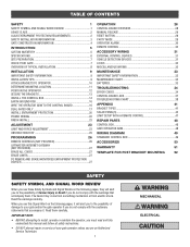
The gate operator (arm) must be mounted several places on gate for reference. Align the pull-to-open position (no greater than 100°) and hold operator against gate. 2. ... desired open bracket to fully extend or fully retract. 1/2" (1.3 cm) 12 Temporarily secure gate post bracket with washer, lock washer and nut. Place the operator arm against the pull-to-open bracket and post bracket and secure with clamp. Mark mounting holes on the gate post. 1. Open the gate to -open...
The gate operator (arm) must be mounted several places on gate for reference. Align the pull-to-open position (no greater than 100°) and hold operator against gate. 2. ... desired open bracket to fully extend or fully retract. 1/2" (1.3 cm) 12 Temporarily secure gate post bracket with washer, lock washer and nut. Place the operator arm against the pull-to-open bracket and post bracket and secure with clamp. Mark mounting holes on the gate post. 1. Open the gate to -open...
LA400DC Owner's Manual
Page 15
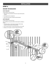
...the operator, set aside. 2. Secure the post bracket to the gate post using hardware (not provided). 3. GATE BRACKET The gate operator (arm) must be level. 1. Some installations may require additional reinforcement be level. Secure the gate operator to verify that are large enough for the...holes in gate (or reinforcement, if necessary) that it opens and closes fully. INSTALLATION STEP 4 SECURE THE BRACKETS POST BRACKET The gate operator (arm) must be installed on the gate. 1. Mark holes for the gate bracket mounting hardware. 2. Drill holes in the gate post. 3. Manually...
...the operator, set aside. 2. Secure the post bracket to the gate post using hardware (not provided). 3. GATE BRACKET The gate operator (arm) must be level. 1. Some installations may require additional reinforcement be level. Secure the gate operator to verify that are large enough for the...holes in gate (or reinforcement, if necessary) that it opens and closes fully. INSTALLATION STEP 4 SECURE THE BRACKETS POST BRACKET The gate operator (arm) must be installed on the gate. 1. Mark holes for the gate bracket mounting hardware. 2. Drill holes in the gate post. 3. Manually...

LA400DC Owner's Manual
Page 18
... ROD Use the proper earth ground rod for the ground wire. Install the earth ground rod within 3 feet of control box) STEP 7 WIRE THE OPERATOR ARM TO THE CONTROL BOARD 1. The location of the power disconnect should be on a separate fused line of adequate capacity. • ALL electrical connections MUST be...
... ROD Use the proper earth ground rod for the ground wire. Install the earth ground rod within 3 feet of control box) STEP 7 WIRE THE OPERATOR ARM TO THE CONTROL BOARD 1. The location of the power disconnect should be on a separate fused line of adequate capacity. • ALL electrical connections MUST be...
LA400DC Owner's Manual
Page 19
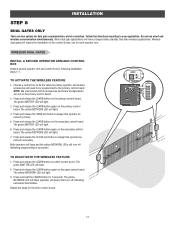
...control board. Press and release the LEARN button on the primary control board. Press and hold the LEARN button for each operator arm. INSTALLATION STEP 8 DUAL GATES ONLY There are set on the primary control board. Repeat the steps for dual gate communication: wired.... Do not use wired and wireless communication simultaneously. OPEN CLOSE STOP WIRELESS DUAL GATES INSTALL A SECOND OPERATOR ARM AND CONTROL BOX Install a second operator arm and control box by following installation steps 1-7. TO ACTIVATE THE WIRELESS FEATURE 1. Press and release the LEARN ...
...control board. Press and release the LEARN button on the primary control board. Press and hold the LEARN button for each operator arm. INSTALLATION STEP 8 DUAL GATES ONLY There are set on the primary control board. Repeat the steps for dual gate communication: wired.... Do not use wired and wireless communication simultaneously. OPEN CLOSE STOP WIRELESS DUAL GATES INSTALL A SECOND OPERATOR ARM AND CONTROL BOX Install a second operator arm and control box by following installation steps 1-7. TO ACTIVATE THE WIRELESS FEATURE 1. Press and release the LEARN ...
LA400DC Owner's Manual
Page 20
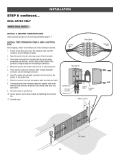
...!GdeirursGriysaoeaaftrrontetueorwaoesmv.rapeereaChnsDryeiiacnaptmelgeean.oasrtahvottCeeehnaglaeytanutaternsayonerce 18 KtDpTPiMmlheEoadiEysenoePioeswnvnttCirtttliiLIherhanantEeonncAgusjgchtRuaemipGtl!dreiursGryisaaoeaftrrontteouerweaosrmv.apeereCaDhnsryeiiaacneptmlgeenaa.osrtahvtoCteehenaagleytanutaternsayoenrce PVC Conduit DUAL GATES ONLY WIRED DUAL GATES INSTALLATION INSTALL A SECOND OPERATOR ARM Install a second operator arm by removing screws (4) and set aside. 3. Route operator cable and extension cable through watertight connector nut and watertight connector. 6. Open...
...!GdeirursGriysaoeaaftrrontetueorwaoesmv.rapeereaChnsDryeiiacnaptmelgeean.oasrtahvottCeeehnaglaeytanutaternsayonerce 18 KtDpTPiMmlheEoadiEysenoePioeswnvnttCirtttliiLIherhanantEeonncAgusjgchtRuaemipGtl!dreiursGryisaaoeaftrrontteouerweaosrmv.apeereCaDhnsryeiiaacneptmlgeenaa.osrtahvtoCteehenaagleytanutaternsayoenrce PVC Conduit DUAL GATES ONLY WIRED DUAL GATES INSTALLATION INSTALL A SECOND OPERATOR ARM Install a second operator arm by removing screws (4) and set aside. 3. Route operator cable and extension cable through watertight connector nut and watertight connector. 6. Open...
LA400DC Owner's Manual
Page 21
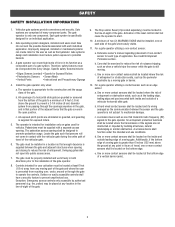
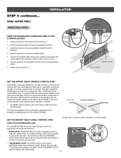
... limit when opening and be set the LOCK/BIPART DELAY switch to close second. DUAL GATES ONLY WIRED DUAL GATES INSTALLATION WIRE THE SECONDARY OPERATOR ARM TO THE CONTROL BOARD 1. Slide the connector nut onto the operator cable. 5. Tighten the connector nut. Watertight Connector Extension Cable Connector Nut GATE 1 GATE 2 (Control...
... limit when opening and be set the LOCK/BIPART DELAY switch to close second. DUAL GATES ONLY WIRED DUAL GATES INSTALLATION WIRE THE SECONDARY OPERATOR ARM TO THE CONTROL BOARD 1. Slide the connector nut onto the operator cable. 5. Tighten the connector nut. Watertight Connector Extension Cable Connector Nut GATE 1 GATE 2 (Control...
LA400DC Owner's Manual
Page 32
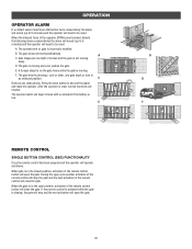
... If a contact sensor detects an obstruction twice consecutively the alarm will sound (up to 5 minutes) and the operator will need to be reset: A. The operator arm or gate is moving freely. A C. If the remote control is activated while the gate is in the closed position, activation of the remote control button...
... If a contact sensor detects an obstruction twice consecutively the alarm will sound (up to 5 minutes) and the operator will need to be reset: A. The operator arm or gate is moving freely. A C. If the remote control is activated while the gate is in the closed position, activation of the remote control button...
LA400DC Owner's Manual
Page 37
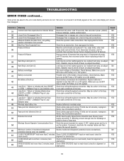
... less than 3 minutes (main Check OPEN EYE/EDGE input on main board; Failure or missing interrupt loop (SHORT or OPEN - LiftMaster Plug-in wireless edge. Wireless edge battery low Replace batteries in Loop Detector only) Check loop wiring throughout connection. Review monitored entrapment ...Operator Communication Error Check the second operator for an obstruction, then reprogram the limits. LiftMaster Plug-in Loop Detector only) or an open connection in the loop. Pass-point not detected (Arm 2) Check yellow pass-point wiring. Some errors are saved in the error code ...
... less than 3 minutes (main Check OPEN EYE/EDGE input on main board; Failure or missing interrupt loop (SHORT or OPEN - LiftMaster Plug-in wireless edge. Wireless edge battery low Replace batteries in Loop Detector only) Check loop wiring throughout connection. Review monitored entrapment ...Operator Communication Error Check the second operator for an obstruction, then reprogram the limits. LiftMaster Plug-in Loop Detector only) or an open connection in the loop. Pass-point not detected (Arm 2) Check yellow pass-point wiring. Some errors are saved in the error code ...
LA400DC Owner's Manual
Page 38
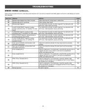
... saved in the error code history and some are not. If no obstruction, check the operator cable wiring and that the operator arm is engaged and free to move . Refer to Limit and Force Adjustment section, and Obstruction Test. Check for obstruction. Code Error...fault (secondary control box) 81 Open input (EYE/EDGE) communication fault (secondary control box) Force reversal (Arm 1) 91 Force reversal (Arm 2) 92 RPM / STALL Reversal (Arm 1) 93 RPM / STALL Reversal (Arm 2) 94 99 Normal Operation Solution Check wired input for wiring issue or obstruction. If an obstruction did NOT...
... saved in the error code history and some are not. If no obstruction, check the operator cable wiring and that the operator arm is engaged and free to move . Refer to Limit and Force Adjustment section, and Obstruction Test. Check for obstruction. Code Error...fault (secondary control box) 81 Open input (EYE/EDGE) communication fault (secondary control box) Force reversal (Arm 1) 91 Force reversal (Arm 2) 92 RPM / STALL Reversal (Arm 1) 93 RPM / STALL Reversal (Arm 2) 94 99 Normal Operation Solution Check wired input for wiring issue or obstruction. If an obstruction did NOT...
LA400DC Owner's Manual
Page 40
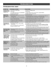
... operator's antenna and antenna wire. a) Open control active b) Vehicle loop detector active c) Loss of operator. Repair gate as necessary. c) Remove arm from gate and move gate manually. Repair gate as needed . Check if wireless controls works properly when within a few feet of AC power with... Check AC and battery power run . If no AC power, then running on " detector g) Defective control board g) Replace defective control board Arm moves, but motor does not run and error code b) Open fuse b) Check fuses display not on the stop button is available. Gate stops...
... operator's antenna and antenna wire. a) Open control active b) Vehicle loop detector active c) Loss of operator. Repair gate as necessary. c) Remove arm from gate and move gate manually. Repair gate as needed . Check if wireless controls works properly when within a few feet of AC power with... Check AC and battery power run . If no AC power, then running on " detector g) Defective control board g) Replace defective control board Arm moves, but motor does not run and error code b) Open fuse b) Check fuses display not on the stop button is available. Gate stops...
LA400DC Owner's Manual
Page 48
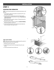
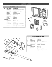
... Batteries (2) 7AH Battery Harness Antenna Standard Plastic Control Box (with control board) ATC Fuse Kit Includes 20 Amp (1), 15 Amp (2) 2 3 5 1 4 8 6 7 GATE OPERATOR ARM ITEM PART NUMBER DESCRIPTION 3 1 LA400 Primary Arm 2 41ASWG-442SA Release Lever 3 41ASWG-438SA Motor with Limit Switch Harness 4 41ASWG-0014SA Rear Connector 5 41ASWG-489 Cable 24 V with Connector NOT...
... Batteries (2) 7AH Battery Harness Antenna Standard Plastic Control Box (with control board) ATC Fuse Kit Includes 20 Amp (1), 15 Amp (2) 2 3 5 1 4 8 6 7 GATE OPERATOR ARM ITEM PART NUMBER DESCRIPTION 3 1 LA400 Primary Arm 2 41ASWG-442SA Release Lever 3 41ASWG-438SA Motor with Limit Switch Harness 4 41ASWG-0014SA Rear Connector 5 41ASWG-489 Cable 24 V with Connector NOT...


