
DC Gate Operators Overview Brochure Manual
Page 1
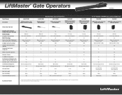
LiftMaster® Gate Operators LA500DC Model Number Description LA5001PKGDC 24VDC Residential / Light Commercial Linear Actuator Photo of Gate Operator Security+ 2.0™ 3 Channel Receiver (50 remote capacity) Battery Backup Exceptional Standby Power MyQ® Technology Best-in-Class Solar Performance (with on board radio (2) 7-AH batteries) DC Motor with Soft Start/Stop Common Control Board... Compliant (Auto Open (or Push Open Slide Gates)) Electronic Limits / Automatic Force Control Board Configuration Plug-in Loops, Anti Tailgate, Quick Close, 3-Second Pre-Motion Warning and 2-...
LiftMaster® Gate Operators LA500DC Model Number Description LA5001PKGDC 24VDC Residential / Light Commercial Linear Actuator Photo of Gate Operator Security+ 2.0™ 3 Channel Receiver (50 remote capacity) Battery Backup Exceptional Standby Power MyQ® Technology Best-in-Class Solar Performance (with on board radio (2) 7-AH batteries) DC Motor with Soft Start/Stop Common Control Board... Compliant (Auto Open (or Push Open Slide Gates)) Electronic Limits / Automatic Force Control Board Configuration Plug-in Loops, Anti Tailgate, Quick Close, 3-Second Pre-Motion Warning and 2-...

DC Gate Operators Overview Brochure Manual
Page 2
... Flexible Wiring Options, simply 'plug-in -Class Solar Performance Ultra-Reliable System delivers power when you to monitor and control your gate operator and lights with your selection for greater peace of standard remotes to access your property by quickly diagnosing... your smartphone for 120V or 230V single phase (LA500DC, CSL24VDC, CSW24VDC). © 2014 LiftMaster All Rights Reserved 845 Larch Ave., Elmhurst, IL 60126 LiftMaster.com LMGTCTCOMP 6/14 Expansion board is optional on LA400DC, LA412DC, RSL12VDC, RSW12VDC, and standard on LA500DC, CSL24VDC, and CSW24VDC. • Plug...
... Flexible Wiring Options, simply 'plug-in -Class Solar Performance Ultra-Reliable System delivers power when you to monitor and control your gate operator and lights with your selection for greater peace of standard remotes to access your property by quickly diagnosing... your smartphone for 120V or 230V single phase (LA500DC, CSL24VDC, CSW24VDC). © 2014 LiftMaster All Rights Reserved 845 Larch Ave., Elmhurst, IL 60126 LiftMaster.com LMGTCTCOMP 6/14 Expansion board is optional on LA400DC, LA412DC, RSL12VDC, RSW12VDC, and standard on LA500DC, CSL24VDC, and CSW24VDC. • Plug...
LA400DC Owner's Manual
Page 3
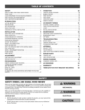
... 23 LIMIT AND FORCE ADJUSTMENT 23 OBSTRUCTION TEST 25 PROGRAMMING 26 REMOTE CONTROLS (NOT PROVIDED 26 LIFTMASTER INTERNET GATEWAY (NOT PROVIDED 27 ERASE ALL CODES 27 ERASE LIMITS 27 TO REMOVE AND ERASE MONITORED ENTRAPMENT PROTECTION DEVICES 27 OPERATION 28 CONTROL BOARD OVERVIEW 28 MANUAL RELEASE 29 RESET BUTTON 29 PARTY MODE 29 OPERATOR...
... 23 LIMIT AND FORCE ADJUSTMENT 23 OBSTRUCTION TEST 25 PROGRAMMING 26 REMOTE CONTROLS (NOT PROVIDED 26 LIFTMASTER INTERNET GATEWAY (NOT PROVIDED 27 ERASE ALL CODES 27 ERASE LIMITS 27 TO REMOVE AND ERASE MONITORED ENTRAPMENT PROTECTION DEVICES 27 OPERATION 28 CONTROL BOARD OVERVIEW 28 MANUAL RELEASE 29 RESET BUTTON 29 PARTY MODE 29 OPERATOR...
LA400DC Owner's Manual
Page 16
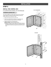
.... 3. A. WALL OR COLUMN MOUNT 9 1/8" 13 3/4" POST MOUNT 6 3/8" 4 3/8" 3 7/8" 5 7/8" 4 7/8" 2 7/8" 12 1/16" 14 Make sure the U-bolts do not protrude more than 3/4 inch from the control box because this can short the control board. Wall or Column: Use the provided screws (4). Post: Use U-bolts and rubber washers (not provided) to the following page. INSTALLATION STEP 5 INSTALL...
.... 3. A. WALL OR COLUMN MOUNT 9 1/8" 13 3/4" POST MOUNT 6 3/8" 4 3/8" 3 7/8" 5 7/8" 4 7/8" 2 7/8" 12 1/16" 14 Make sure the U-bolts do not protrude more than 3/4 inch from the control box because this can short the control board. Wall or Column: Use the provided screws (4). Post: Use U-bolts and rubber washers (not provided) to the following page. INSTALLATION STEP 5 INSTALL...

LA400DC Owner's Manual
Page 18
... • DO NOT install ANY wiring or attempt to run in separate conduit. If installing one operator, proceed to the following page. 16 (control board) GATE 1 GATE 2 Connector Operator Cable Watertight Connector Connector Nut Never splice two wires for your local area. Install the earth ground rod within ...3 feet of control box) STEP 7 WIRE THE OPERATOR ARM TO THE CONTROL BOARD 1. The earth ground wire will be a single, whole piece of the power disconnect should cut the ground wire...
... • DO NOT install ANY wiring or attempt to run in separate conduit. If installing one operator, proceed to the following page. 16 (control board) GATE 1 GATE 2 Connector Operator Cable Watertight Connector Connector Nut Never splice two wires for your local area. Install the earth ground rod within ...3 feet of control box) STEP 7 WIRE THE OPERATOR ARM TO THE CONTROL BOARD 1. The earth ground wire will be a single, whole piece of the power disconnect should cut the ground wire...
LA400DC Owner's Manual
Page 19
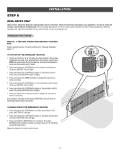
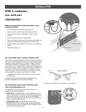
...The yellow NETWORK LED will have a longer battery standby time than wireless applications. Press and release the LEARN button on the primary control board. Press and release the CLOSE test button to assign this operator as network primary. 5. Press and hold the LEARN button for dual...operators will beep and the yellow NETWORK LEDs will need to your application. INSTALLATION STEP 8 DUAL GATES ONLY There are set on the primary control board. 2. The yellow NETWORK LED will blink (operator will light. 3. The green XMITTER LED will light. 2. The green XMITTER LED will...
...The yellow NETWORK LED will have a longer battery standby time than wireless applications. Press and release the LEARN button on the primary control board. Press and release the CLOSE test button to assign this operator as network primary. 5. Press and hold the LEARN button for dual...operators will beep and the yellow NETWORK LEDs will need to your application. INSTALLATION STEP 8 DUAL GATES ONLY There are set on the primary control board. 2. The yellow NETWORK LED will blink (operator will light. 3. The green XMITTER LED will light. 2. The green XMITTER LED will...
LA400DC Owner's Manual
Page 21
...gate travels a longer distance than the other . The BIPART DELAY switch on Control Board. To synchronize the closing of the gates, set to the Gate 2 connector and the operator on the control board. STEP 8 continued... Insert the extension cable through the watertight connector. 3. ...Primary Gate OUTSIDE PROPERTY SET THE BIPART DELAY (DUAL CONTROL BOX) Primary Gate - Tighten the connector nut. Connect to Gate 1 Connector on the control board needs to be connected to Gate 1 connections on the opposite side to red, etc.). ...
...gate travels a longer distance than the other . The BIPART DELAY switch on Control Board. To synchronize the closing of the gates, set to the Gate 2 connector and the operator on the control board. STEP 8 continued... Insert the extension cable through the watertight connector. 3. ...Primary Gate OUTSIDE PROPERTY SET THE BIPART DELAY (DUAL CONTROL BOX) Primary Gate - Tighten the connector nut. Connect to Gate 1 Connector on the control board needs to be connected to Gate 1 connections on the opposite side to red, etc.). ...
LA400DC Owner's Manual
Page 24
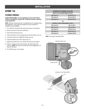
Turn off the AC power from the main power source circuit breaker. 2. The control board will power up. OPERATOR POWER SOURCE DIRECT PLUG-IN TRANSFORMER (120 VAC) Wire Gauge 14 350 feet (107 m) Wire Gauge 12 525 feet (160 m) ...earth ground rod wire using NEC guidelines. Plug the J15 plug into the board. 9. NOTE: You may see a small spark when plugging the J15 plug into the control board. STANDARD CONTROL BOX J15 Plug Junction Box Cover EXTERNAL PLUG-IN TRANSFORMER Control Box 22 Transformer INSTALLATION STEP 10 POWER WIRING SOLAR APPLICATIONS: For solar applications...
Turn off the AC power from the main power source circuit breaker. 2. The control board will power up. OPERATOR POWER SOURCE DIRECT PLUG-IN TRANSFORMER (120 VAC) Wire Gauge 14 350 feet (107 m) Wire Gauge 12 525 feet (160 m) ...earth ground rod wire using NEC guidelines. Plug the J15 plug into the board. 9. NOTE: You may see a small spark when plugging the J15 plug into the control board. STANDARD CONTROL BOX J15 Plug Junction Box Cover EXTERNAL PLUG-IN TRANSFORMER Control Box 22 Transformer INSTALLATION STEP 10 POWER WIRING SOLAR APPLICATIONS: For solar applications...
LA400DC Owner's Manual
Page 25
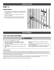
...installed safety reversal system, persons (particularly small children) could be fine tuned using the control board (following page) or a remote control (refer to compensate for a binding or sticking gate. • If one control (force or travel limits) is adjusted automatically when you to make travel limit and ...sides of force required to open and close the gate. Setting the limits with a rigid object. Gate MUST reverse on the control board will interfere with proper operation of safety reversal system. • NEVER increase force beyond minimum amount required to move gate. ...
...installed safety reversal system, persons (particularly small children) could be fine tuned using the control board (following page) or a remote control (refer to compensate for a binding or sticking gate. • If one control (force or travel limits) is adjusted automatically when you to make travel limit and ...sides of force required to open and close the gate. Setting the limits with a rigid object. Gate MUST reverse on the control board will interfere with proper operation of safety reversal system. • NEVER increase force beyond minimum amount required to move gate. ...
LA400DC Owner's Manual
Page 26
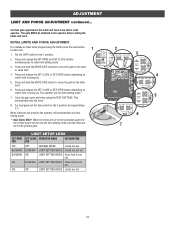
... are set properly the operator will automatically exit limit setting mode. * Dual Gates ONLY: When the limits are set on the secondary gate first the control board will not exit the limit setting mode until the limits are set on the primary gate. 1 E E PRESS & RELEASE TO BEGIN LIMIT SETUP 1 2 GATE 2 OFF TIMER...
... are set properly the operator will automatically exit limit setting mode. * Dual Gates ONLY: When the limits are set on the secondary gate first the control board will not exit the limit setting mode until the limits are set on the primary gate. 1 E E PRESS & RELEASE TO BEGIN LIMIT SETUP 1 2 GATE 2 OFF TIMER...

LA400DC Owner's Manual
Page 27
... the solid object, and the rigid structure can withstand the forces generated during motion, the operator will not reverse by turning the force control slightly clockwise. 3. The gate should stop the gate. SET OPEN SET CLOSE PRESS & RELEASE OBSTRUCTION TEST 1 The operator is stopping ...ready to make additional force adjustments. ADJUSTMENT LIMIT AND FORCE ADJUSTMENT continued... FINE TUNE THE FORCE The REVERSAL FORCE DIAL on the control board is the same for the open or closed position, increase the force by itself nor cause nuisance interruptions, but MUST reverse ...
... the solid object, and the rigid structure can withstand the forces generated during motion, the operator will not reverse by turning the force control slightly clockwise. 3. The gate should stop the gate. SET OPEN SET CLOSE PRESS & RELEASE OBSTRUCTION TEST 1 The operator is stopping ...ready to make additional force adjustments. ADJUSTMENT LIMIT AND FORCE ADJUSTMENT continued... FINE TUNE THE FORCE The REVERSAL FORCE DIAL on the control board is the same for the open or closed position, increase the force by itself nor cause nuisance interruptions, but MUST reverse ...
LA400DC Owner's Manual
Page 29
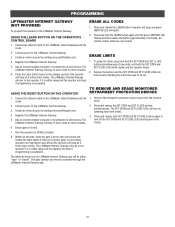
... programming is at the open " or "closed . 7. Press and release the LEARN button (operator will beep and green XMITTER LED will need to the LiftMaster Internet Gateway: USING THE LEARN BUTTON ON THE OPERATOR'S CONTROL BOARD 1. Press the Learn button twice on the primary operator (the operator will beep as shown by the...
... programming is at the open " or "closed . 7. Press and release the LEARN button (operator will beep and green XMITTER LED will need to the LiftMaster Internet Gateway: USING THE LEARN BUTTON ON THE OPERATOR'S CONTROL BOARD 1. Press the Learn button twice on the primary operator (the operator will beep as shown by the...

LA400DC Owner's Manual
Page 30
... gate to automatically open and then latch at the OPEN limit until AC power restored or battery voltage increases. • Constant pressure on the control board prior to the desired setting. The operator type will show after a specified time period. If the TTC is OFF. The firmware version will ... either open or close the gate when the operator is in the Troubleshooting section. 11 Error Code Display: The error code display will display as LA400DC. The range is 0 to 180 seconds, 0 seconds is set to the OFF position, then the gate will close the gate after the operator...
... gate to automatically open and then latch at the OPEN limit until AC power restored or battery voltage increases. • Constant pressure on the control board prior to the desired setting. The operator type will show after a specified time period. If the TTC is OFF. The firmware version will ... either open or close the gate when the operator is in the Troubleshooting section. 11 Error Code Display: The error code display will display as LA400DC. The range is 0 to 180 seconds, 0 seconds is set to the OFF position, then the gate will close the gate after the operator...
LA400DC Owner's Manual
Page 33
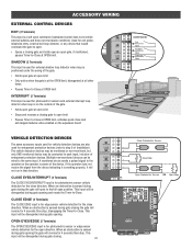
... maintained, pauses Timer-to-Close at OPEN limit, activates quick close and anti-tailgate features when enabled on the expansion board (control board) Exit Com Shadow Com Interrupt Com Interrupt Loop Shadow Loop Exit Loop VEHICLE DETECTION DEVICES The same accessory inputs used for...OPEN EYES/EDGE input is for photoelectric sensor or edge sensor vehicle detection for entrapment protection devices (refer to -Close. ACCESSORY WIRING EXTERNAL CONTROL DEVICES EXIT (2 Terminals) This input is a soft open direction. Multiple non-monitored devices can be connected to -Close. CLOSE EYES/INTERRUPT...
... maintained, pauses Timer-to-Close at OPEN limit, activates quick close and anti-tailgate features when enabled on the expansion board (control board) Exit Com Shadow Com Interrupt Com Interrupt Loop Shadow Loop Exit Loop VEHICLE DETECTION DEVICES The same accessory inputs used for...OPEN EYES/EDGE input is for photoelectric sensor or edge sensor vehicle detection for entrapment protection devices (refer to -Close. ACCESSORY WIRING EXTERNAL CONTROL DEVICES EXIT (2 Terminals) This input is a soft open direction. Multiple non-monitored devices can be connected to -Close. CLOSE EYES/INTERRUPT...
LA400DC Owner's Manual
Page 34
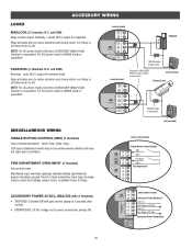
... DEPARTMENT OPEN INPUT (2 Terminals) Acts as single button control and safeties remain active, re-enables Timer-to motor activation and during motor run . For DC power install a 1N4005 diode or equivalent. (control board) Maglock (control board) 1N4005 diode or equivalent. Relay activates prior to power... accessories, always ON. 1N4005 diode or equivalent. - + (not provided) (main control board) Single Button Control Station SBC Com Fire Dept Com Fire Department (main control board) Accessory Power Switched Com (-) Acc Power +24 Vdc Com (-) Acc Power +24 Vdc Accessory...
... DEPARTMENT OPEN INPUT (2 Terminals) Acts as single button control and safeties remain active, re-enables Timer-to motor activation and during motor run . For DC power install a 1N4005 diode or equivalent. (control board) Maglock (control board) 1N4005 diode or equivalent. Relay activates prior to power... accessories, always ON. 1N4005 diode or equivalent. - + (not provided) (main control board) Single Button Control Station SBC Com Fire Dept Com Fire Department (main control board) Accessory Power Switched Com (-) Acc Power +24 Vdc Com (-) Acc Power +24 Vdc Accessory...
LA400DC Owner's Manual
Page 35
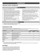
... activates the noncontact sensors. Have a qualified service person make repairs to gate hardware. • ALL maintenance MUST be performed by a LiftMaster professional. • Activate gate ONLY when it can increase the risk of the operator's rating. Using a digital voltmeter, verify that ... operator should be returned to service. • Disconnect power at the fuse box BEFORE proceeding. ALWAYS disconnect the batteries to the control board and DOES NOT turn off battery power. BATTERIES Batteries will degrade over time depending on a separate fused line of adequate capacity. ...
... activates the noncontact sensors. Have a qualified service person make repairs to gate hardware. • ALL maintenance MUST be performed by a LiftMaster professional. • Activate gate ONLY when it can increase the risk of the operator's rating. Using a digital voltmeter, verify that ... operator should be returned to service. • Disconnect power at the fuse box BEFORE proceeding. ALWAYS disconnect the batteries to the control board and DOES NOT turn off battery power. BATTERIES Batteries will degrade over time depending on a separate fused line of adequate capacity. ...
LA400DC Owner's Manual
Page 36
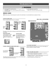
... ERROR CODES The error codes are shown on the following page for six seconds. starting with fuse of same type and rating. Refer to the control board, it is recommended that occurred A SECOND LATER.... Press and hold the OPEN button until a new error occurs. 3. The display will show the sequence of errors...
... ERROR CODES The error codes are shown on the following page for six seconds. starting with fuse of same type and rating. Refer to the control board, it is recommended that occurred A SECOND LATER.... Press and hold the OPEN button until a new error occurs. 3. The display will show the sequence of errors...
LA400DC Owner's Manual
Page 37
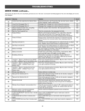
.... Linear Drive Disengaged (Arm 1) Disengage then re-engage arm, check wiring and connections. LiftMaster Plug-in the loop. Brownout occurred AC/DC board supply dipped below allowable level. Minimum number of the battery charge harness. If issue continues, replace control board. If so, erase limits, enter limit setup mode and set too tightly against...
.... Linear Drive Disengaged (Arm 1) Disengage then re-engage arm, check wiring and connections. LiftMaster Plug-in the loop. Brownout occurred AC/DC board supply dipped below allowable level. Minimum number of the battery charge harness. If issue continues, replace control board. If so, erase limits, enter limit setup mode and set too tightly against...
LA400DC Owner's Manual
Page 39
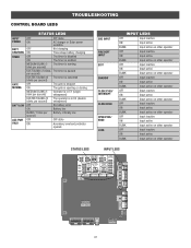
TROUBLESHOOTING CONTROL BOARD LEDS STATUS LEDS INPUT OFF POWER ON OFF state AC charger or Solar power available BATT OFF CHARGING ON Not charging Three stage battery charging ...
TROUBLESHOOTING CONTROL BOARD LEDS STATUS LEDS INPUT OFF POWER ON OFF state AC charger or Solar power available BATT OFF CHARGING ON Not charging Three stage battery charging ...
LA400DC Owner's Manual
Page 40
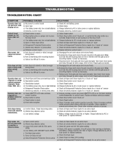
... or retract enough during travel b) Arm is interfering with mounting bracket c) Gate is not "stuck on " detector g) Defective control board g) Replace defective control board Arm moves, but will not close when setting limits. Repair gate as needed. Operator does not respond to a wired... is not "stuck on" c) Check Reset button d) Charges batteries by AC or solar power or replace batteries d) Defective control board d) Replace defective control board Control board powers up, but motor does not run and error code b) Open fuse b) Check fuses display not on batteries and battery...
... or retract enough during travel b) Arm is interfering with mounting bracket c) Gate is not "stuck on " detector g) Defective control board g) Replace defective control board Arm moves, but will not close when setting limits. Repair gate as needed. Operator does not respond to a wired... is not "stuck on" c) Check Reset button d) Charges batteries by AC or solar power or replace batteries d) Defective control board d) Replace defective control board Control board powers up, but motor does not run and error code b) Open fuse b) Check fuses display not on batteries and battery...


