

LA400 Manual
Page 2
...Your Gate Mounting Options Manual Release Determine Position of the Pull-to-Open Bracket Determine Position of the "Optional" Push-to-Open Bracket Assemble Gate Post Bracket (Pull-to-Open) Attach Brackets to Gate Operator Determine Mounting Location Measuring and Marking...Box (XLM) WIRING Connect the Gate Operator (Gate 1) to the Control Box Set the Bipart Delay (Model LA400-S Only) Connect the Gate Operator (Gate 2) to the Control Box (Model LA400-S Only) Junction Box (Model LA400-S Only) Connect Transformer to Control Board Earth Ground Rod Installation (Optional) Connect Batteries 1-6 1 2 3 ...
...Your Gate Mounting Options Manual Release Determine Position of the Pull-to-Open Bracket Determine Position of the "Optional" Push-to-Open Bracket Assemble Gate Post Bracket (Pull-to-Open) Attach Brackets to Gate Operator Determine Mounting Location Measuring and Marking...Box (XLM) WIRING Connect the Gate Operator (Gate 1) to the Control Box Set the Bipart Delay (Model LA400-S Only) Connect the Gate Operator (Gate 2) to the Control Box (Model LA400-S Only) Junction Box (Model LA400-S Only) Connect Transformer to Control Board Earth Ground Rod Installation (Optional) Connect Batteries 1-6 1 2 3 ...

LA400 Manual
Page 3
This system must be used for use in both the open and close directions of entrapment protection. Type E: Built-in a home of contact with a solid object. UL325 ENTRAPMENT PROTECTION REQUIREMENTS GATE OPERATOR ENTRAPMENT PROTECTION... in audio alarm. Examples include sirens, horns or buzzers. That means that is installed on this operator. SAFETY ACCESSORY SELECTION All UL325 compliant LiftMaster gate operators will accept external entrapment protection devices to complete a proper installation you must provide the following as your primary type of entrapment protection ...
This system must be used for use in both the open and close directions of entrapment protection. Type E: Built-in a home of contact with a solid object. UL325 ENTRAPMENT PROTECTION REQUIREMENTS GATE OPERATOR ENTRAPMENT PROTECTION... in audio alarm. Examples include sirens, horns or buzzers. That means that is installed on this operator. SAFETY ACCESSORY SELECTION All UL325 compliant LiftMaster gate operators will accept external entrapment protection devices to complete a proper installation you must provide the following as your primary type of entrapment protection ...

LA400 Manual
Page 4
... the gate operator only when: a. The operator is supplied for each side of nuisance tripping, such as the bystander. All openings of a gate system. Controls intended for entrapment protection functions shall be located where the risk of entrapment or obstruction exists, such...All exposed pinch points are comprised of the gate. Pedestrians must reduce public exposure to prevent unauthorized use conditions. The pedestrian access opening . The gate must be installed in the lineof-sight of many component parts. Outdoor or easily accessible controls shall have a ...
... the gate operator only when: a. The operator is supplied for each side of nuisance tripping, such as the bystander. All openings of a gate system. Controls intended for entrapment protection functions shall be located where the risk of entrapment or obstruction exists, such...All exposed pinch points are comprised of the gate. Pedestrians must reduce public exposure to prevent unauthorized use conditions. The pedestrian access opening . The gate must be installed in the lineof-sight of many component parts. Outdoor or easily accessible controls shall have a ...

LA400 Manual
Page 5
...bearing exposed rollers 8 feet (2.44 m), or less, above grade. Exceptions. 3.2.2 Positive stops shall be required to limit travel to the designed fully open and 1.3 Gates shall have smooth bottom edges, with vertical bottom edged fully closed positions. gate will enter a receiver guide, refer to ASTM F2200 ... 1.9 A pedestrian gate shall not be designed, guarded or screened to prevent a 4 inch (102 mm) diameter sphere from passing through the openings anywhere in the gate, and in that portion of the gate, or at that is required to perform their movement shall not be automated. ...
...bearing exposed rollers 8 feet (2.44 m), or less, above grade. Exceptions. 3.2.2 Positive stops shall be required to limit travel to the designed fully open and 1.3 Gates shall have smooth bottom edges, with vertical bottom edged fully closed positions. gate will enter a receiver guide, refer to ASTM F2200 ... 1.9 A pedestrian gate shall not be designed, guarded or screened to prevent a 4 inch (102 mm) diameter sphere from passing through the openings anywhere in the gate, and in that portion of the gate, or at that is required to perform their movement shall not be automated. ...

LA400 Manual
Page 6
... protect in SEVERE INJURY to persons and/or damage to the operator or in fire. Failure to do so may result in BOTH the open into public access ways. ADJUSTMENT Without a properly installed safety reversal system, persons (particularly small children) could be SERIOUSLY INJURED or KILLED by.... ALWAYS wear protective gloves and eye protection when changing the battery or working around the battery compartment. • DO NOT use only LiftMaster part #K74-30762 for disposal instructions. WIRING To reduce the risk of the gate in PLAIN VIEW. • Permanently secure each warning...
... protect in SEVERE INJURY to persons and/or damage to the operator or in fire. Failure to do so may result in BOTH the open into public access ways. ADJUSTMENT Without a properly installed safety reversal system, persons (particularly small children) could be SERIOUSLY INJURED or KILLED by.... ALWAYS wear protective gloves and eye protection when changing the battery or working around the battery compartment. • DO NOT use only LiftMaster part #K74-30762 for disposal instructions. WIRING To reduce the risk of the gate in PLAIN VIEW. • Permanently secure each warning...

LA400 Manual
Page 8
... m) • Junction Box - Six Conductor, 9 feet (2.7 m) • Warning Sign (2) • Battery (2) • Plug-in Transformer (1) LA400-S (SECOND GATE OPERATOR ARM) • Motor Cable - INTRODUCTION » OPERATOR SPECIFICATIONS + CARTON INVENTORY OPERATOR SPECIFICATIONS Operating Cycles: Main Supply (Motor): Current...DIA.) 37.4" (95 cm) 53.5" (136 cm) CARTON INVENTORY Carton inventory is doubled except for a 90° opening 4 Minutes -20° C to + 50° C -4° F to -Open Bracket (1) • Hex Bolt 5/16"-18 X 1-1/2" (5) • Square Neck Carriage Bolt 3/8"-16 X 6" ...
... m) • Junction Box - Six Conductor, 9 feet (2.7 m) • Warning Sign (2) • Battery (2) • Plug-in Transformer (1) LA400-S (SECOND GATE OPERATOR ARM) • Motor Cable - INTRODUCTION » OPERATOR SPECIFICATIONS + CARTON INVENTORY OPERATOR SPECIFICATIONS Operating Cycles: Main Supply (Motor): Current...DIA.) 37.4" (95 cm) 53.5" (136 cm) CARTON INVENTORY Carton inventory is doubled except for a 90° opening 4 Minutes -20° C to + 50° C -4° F to -Open Bracket (1) • Hex Bolt 5/16"-18 X 1-1/2" (5) • Square Neck Carriage Bolt 3/8"-16 X 6" ...

LA400 Manual
Page 10
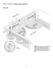
... Control Box with Batteries Hinge Post Bracket Gate Bracket PVC Conduit (not provided) to reduce the risk of entrapment or obstruction exists at either the opening or closing direction. Care shall be located where the risk of nuisance tripping, such as when a vehicle trips the sensor while the gate is still...
... Control Box with Batteries Hinge Post Bracket Gate Bracket PVC Conduit (not provided) to reduce the risk of entrapment or obstruction exists at either the opening or closing direction. Care shall be located where the risk of nuisance tripping, such as when a vehicle trips the sensor while the gate is still...
LA400 Manual
Page 11
... Operator Cable Gate 2 Junction Box Extension Cable Photoelectric Sensors PVC Conduit (not provided) to reduce the risk of entrapment or obstruction exists at either the opening or closing direction.
... Operator Cable Gate 2 Junction Box Extension Cable Photoelectric Sensors PVC Conduit (not provided) to reduce the risk of entrapment or obstruction exists at either the opening or closing direction.
LA400 Manual
Page 13
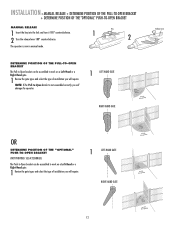
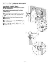
...operator. 1 LEFT-HAND GATE RIGHT-HAND GATE Release Lever OR DETERMINE POSITION OF THE "OPTIONAL" PUSH-TO-OPEN BRACKET (NOT PROVIDED. Key 1 2 DETERMINE POSITION OF THE PULL-TO-OPEN BRACKET The Pull-to-Open bracket can be assembled to work on a Left-Hand or a Right-Hand gate. 1 Review the ...LEFT-HAND GATE RIGHT-HAND GATE 12 NOTE: If the Pull-to-Open bracket is now in manual mode. INSTALLATION » MANUAL RELEASE + DETERMINE POSITION OF THE PULL-TO-OPEN BRACKET + DETERMINE POSITION OF THE "OPTIONAL" PUSH-TO-OPEN BRACKET MANUAL RELEASE 1 Insert the key into the lock and turn it...
...operator. 1 LEFT-HAND GATE RIGHT-HAND GATE Release Lever OR DETERMINE POSITION OF THE "OPTIONAL" PUSH-TO-OPEN BRACKET (NOT PROVIDED. Key 1 2 DETERMINE POSITION OF THE PULL-TO-OPEN BRACKET The Pull-to-Open bracket can be assembled to work on a Left-Hand or a Right-Hand gate. 1 Review the ...LEFT-HAND GATE RIGHT-HAND GATE 12 NOTE: If the Pull-to-Open bracket is now in manual mode. INSTALLATION » MANUAL RELEASE + DETERMINE POSITION OF THE PULL-TO-OPEN BRACKET + DETERMINE POSITION OF THE "OPTIONAL" PUSH-TO-OPEN BRACKET MANUAL RELEASE 1 Insert the key into the lock and turn it...
LA400 Manual
Page 14
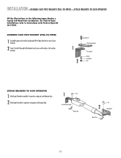
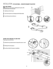
... on the following pages display a typical Left-Hand Gate installation. For Push-to-Open installations refer to instructions with washer, lock washer and nut. 1 2 HeexxBBolot l3t/38/"8" Extension PBurlla-tcok-Oepten Bracket PPoostsBtrBacrkaectket WWaashsehrer LLoockckWaWshaesr her ...and hairpin clips. 1 Pin Post Bracket Assembly Hairpin Clip Pin 2 Gate Bracket Hairpin Clip 13 INSTALLATION » ASSEMBLE GATE POST BRACKET (PULL-TO-OPEN) + ATTACH BRACKETS TO GATE OPERATOR All the illustrations on top of post bracket. 2 Insert the bolt through both brackets and secure with Push-to...
... on the following pages display a typical Left-Hand Gate installation. For Push-to-Open installations refer to instructions with washer, lock washer and nut. 1 2 HeexxBBolot l3t/38/"8" Extension PBurlla-tcok-Oepten Bracket PPoostsBtrBacrkaectket WWaashsehrer LLoockckWaWshaesr her ...and hairpin clips. 1 Pin Post Bracket Assembly Hairpin Clip Pin 2 Gate Bracket Hairpin Clip 13 INSTALLATION » ASSEMBLE GATE POST BRACKET (PULL-TO-OPEN) + ATTACH BRACKETS TO GATE OPERATOR All the illustrations on top of post bracket. 2 Insert the bolt through both brackets and secure with Push-to...
LA400 Manual
Page 15
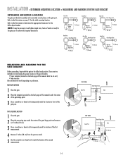
... bracket assembly can be mounted several places on page 11 for the ideal mounting location. Refer to achieve the required dimensions. Must be necessary to -Open bracket. Either method will work depending on preference.
... bracket assembly can be mounted several places on page 11 for the ideal mounting location. Refer to achieve the required dimensions. Must be necessary to -Open bracket. Either method will work depending on preference.
LA400 Manual
Page 16
...) must be mounted several places on gate for mounting options. 1 Open the gate to -Open bracket and post bracket and secure with clamp. Refer to page 11 for reference. Temporarily secure the gate bracket using a clamp. 4 Align the Pull-to-Open bracket to a position as CLOSE AS POSSIBLE above the screwdriver or... dowel rod. 5 Insert hex bolt through Pull-to desired open position (no greater than 100°) and hold operator against gate. 2 Place the operator arm against gate post at the desired position. Temporarily secure ...
...) must be mounted several places on gate for mounting options. 1 Open the gate to -Open bracket and post bracket and secure with clamp. Refer to page 11 for reference. Temporarily secure the gate bracket using a clamp. 4 Align the Pull-to-Open bracket to a position as CLOSE AS POSSIBLE above the screwdriver or... dowel rod. 5 Insert hex bolt through Pull-to desired open position (no greater than 100°) and hold operator against gate. 2 Place the operator arm against gate post at the desired position. Temporarily secure ...
LA400 Manual
Page 17
...187; TEST GATE TRAVEL + SECURE POST BRACKET TO GATE POST TEST GATE TRAVEL NOTE: If gate does not open and close completely adjust the position of the 1 gate bracket and mark new mounting holes. 1 Manually open and close the gate. 2 Ensure that the operator does not bind against the Pull-to...-Open bracket. 3 Ensure that the piston does not bottom out. 2 1/2" (1.3 cm) 3 Do not allow piston to the gate ...
...187; TEST GATE TRAVEL + SECURE POST BRACKET TO GATE POST TEST GATE TRAVEL NOTE: If gate does not open and close completely adjust the position of the 1 gate bracket and mark new mounting holes. 1 Manually open and close the gate. 2 Ensure that the operator does not bind against the Pull-to...-Open bracket. 3 Ensure that the piston does not bottom out. 2 1/2" (1.3 cm) 3 Do not allow piston to the gate ...
LA400 Manual
Page 18
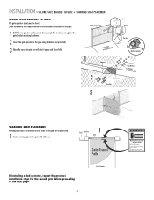
...). 3 Manually move at any time without prior warning. Do not let children operate the gate or play in gate (or reinforcement, if necessary) that it opens and closes fully. This entrance is for the second gate before proceeding to the gate with cable ties. Fence Gate Post 1 Gate Gate Travel Path...
...). 3 Manually move at any time without prior warning. Do not let children operate the gate or play in gate (or reinforcement, if necessary) that it opens and closes fully. This entrance is for the second gate before proceeding to the gate with cable ties. Fence Gate Post 1 Gate Gate Travel Path...

LA400 Manual
Page 19
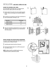
... MUST be mounted within 5 feet (1.5 m) of the gate operator. Wall C. Mount the control box as high as possible for best radio reception. 1 Remove screws and open the control box. 1 2 Disconnect the reset button, alarm, and coaxial connector. 3 Loosen screws to remove the control board and mounting bracket. 4 Remove the control board...
... MUST be mounted within 5 feet (1.5 m) of the gate operator. Wall C. Mount the control box as high as possible for best radio reception. 1 Remove screws and open the control box. 1 2 Disconnect the reset button, alarm, and coaxial connector. 3 Loosen screws to remove the control board and mounting bracket. 4 Remove the control board...
LA400 Manual
Page 21
.... The knock out will accommodate a 3/8" diameter 'U' bolt. 2 Type and Size Standard 3" Round Pipe Standard 4" Square Post Standard 6" Square Post 'U' Bolt Opening 3-1/2" 4" 6" 3 Select center mounting holes (top and bottom) knock out using a metal control box to prevent serious injury to persons or damage to one... screwdriver and hammer. INSTALLATION » LARGE METAL CONTROL BOX (XLM) MOUNT THE CONTROL BOX (XLM) The control box MUST be removed by opening the door 90°. See chart below. complete. Use knock outs located at the 4 corners of the gate operator. 1 90° ...
.... The knock out will accommodate a 3/8" diameter 'U' bolt. 2 Type and Size Standard 3" Round Pipe Standard 4" Square Post Standard 6" Square Post 'U' Bolt Opening 3-1/2" 4" 6" 3 Select center mounting holes (top and bottom) knock out using a metal control box to prevent serious injury to persons or damage to one... screwdriver and hammer. INSTALLATION » LARGE METAL CONTROL BOX (XLM) MOUNT THE CONTROL BOX (XLM) The control box MUST be removed by opening the door 90°. See chart below. complete. Use knock outs located at the 4 corners of the gate operator. 1 90° ...

LA400 Manual
Page 22
... GATE 2 LEARN XMITTER ON OFF LOCK / BIPA RT DELAY CLOSE EDGE OPEN EDGE/ PHOTO OPEN PHOTO SET OPEN LIMIT GATE 1 CLOSE PHOTO SET CLOSE LIMIT LEARN LIMITS FORCE GATE 2 ON OFF AUTO OPEN LOW BATT OFF MAX SINGLE BUTTON TIMER TO CLOSE OPEN CONTROL INPUTS SINGLE BUTTON RESET OFF MAX STOP CTRL PWR CTRL PWR...
... GATE 2 LEARN XMITTER ON OFF LOCK / BIPA RT DELAY CLOSE EDGE OPEN EDGE/ PHOTO OPEN PHOTO SET OPEN LIMIT GATE 1 CLOSE PHOTO SET CLOSE LIMIT LEARN LIMITS FORCE GATE 2 ON OFF AUTO OPEN LOW BATT OFF MAX SINGLE BUTTON TIMER TO CLOSE OPEN CONTROL INPUTS SINGLE BUTTON RESET OFF MAX STOP CTRL PWR CTRL PWR...
LA400 Manual
Page 23
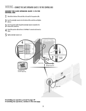
... BRN D1Ø GRN WHT YEL BLU RED Z12 ACCESSORY POWER GATE 1 BRN GRN WHT U4 YEL BLU RED 3 MAX C13 C4 F6 F2 FUSE OPEN Nut 52 Operator Cable 1 Watertight Connector Nut Terminal blocks can be used for the operator cable. 2 Insert the watertight connector into the bottom of the...
... BRN D1Ø GRN WHT YEL BLU RED Z12 ACCESSORY POWER GATE 1 BRN GRN WHT U4 YEL BLU RED 3 MAX C13 C4 F6 F2 FUSE OPEN Nut 52 Operator Cable 1 Watertight Connector Nut Terminal blocks can be used for the operator cable. 2 Insert the watertight connector into the bottom of the...

LA400 Manual
Page 24
... If a solenoid lock is no appropriate location on that the control box be set as this gate. NOTE: The gate with the longer travel span (opening) must be installed on the control board. Connect to Gate 1 Connector on a gate, the gate with a decorative overlapping piece on the outside of the... LA400-S ONLY) In some dual gate installations, one gate or if using a solenoid lock, for the control box, then mount the control box on the opposite side, but connect the operator closest to the control box to the Gate 2 connector and 1 the operator on one gate will need to open first...
... If a solenoid lock is no appropriate location on that the control box be set as this gate. NOTE: The gate with the longer travel span (opening) must be installed on the control board. Connect to Gate 1 Connector on a gate, the gate with a decorative overlapping piece on the outside of the... LA400-S ONLY) In some dual gate installations, one gate or if using a solenoid lock, for the control box, then mount the control box on the opposite side, but connect the operator closest to the control box to the Gate 2 connector and 1 the operator on one gate will need to open first...

LA400 Manual
Page 26
... the bottom of the junction box (not provided). 6 Secure with 3/4" NPT threaded port holes • Screws • PVC Conduit 1 1 Open the junction box by removing screws (4) and set aside. 2 Select holes to complete the junction box installation: • 4 x 4 Junction Box...Operator OpCeraatbolreCable Screws (4) 5 Insert cables and watertight connectors into the holes in the bottom of second operator. WIRING » JUNCTION BOX (MODEL LA400-S ONLY) JUNCTION BOX The following items are required to be used for the watertight connectors. 2 3 Mount the junction box within 5 feet ...
... the bottom of the junction box (not provided). 6 Secure with 3/4" NPT threaded port holes • Screws • PVC Conduit 1 1 Open the junction box by removing screws (4) and set aside. 2 Select holes to complete the junction box installation: • 4 x 4 Junction Box...Operator OpCeraatbolreCable Screws (4) 5 Insert cables and watertight connectors into the holes in the bottom of second operator. WIRING » JUNCTION BOX (MODEL LA400-S ONLY) JUNCTION BOX The following items are required to be used for the watertight connectors. 2 3 Mount the junction box within 5 feet ...


