
LA400 Manual
Page 11
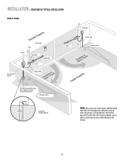
... the risk of nuisance tripping, such as when a vehicle trips the sensor while the gate is still moving. 10 INSTALLATION » OVERVIEW OF TYPICAL INSTALLATION DUAL GATE Warning Sign Hinge Antenna Post Bracket Gate Bracket Gate 1 Control Box with Batteries Operator Cable Gate 2 Junction Box Extension Cable Photoelectric Sensors PVC Conduit...
... the risk of nuisance tripping, such as when a vehicle trips the sensor while the gate is still moving. 10 INSTALLATION » OVERVIEW OF TYPICAL INSTALLATION DUAL GATE Warning Sign Hinge Antenna Post Bracket Gate Bracket Gate 1 Control Box with Batteries Operator Cable Gate 2 Junction Box Extension Cable Photoelectric Sensors PVC Conduit...

LA400 Manual
Page 24
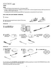
..., it is OFF. The range is 0 to 8 seconds, 0 seconds is the primary gate. Primary Gate OUTSIDE PROPERTY 23 The following illustration shows a dual gate configuration with the lock attached to it is no appropriate location on that the control box be installed on the same side as the... primary gate (GATE 1). 1 Set the Bipart Delay to desired setting. WIRING » SET THE BIPART DELAY (MODEL LA400-S ONLY) SET THE BIPART DELAY (MODEL LA400-S ONLY) In some dual gate installations, one gate or if using a solenoid lock, for the control box, then mount the control box on the...
..., it is OFF. The range is 0 to 8 seconds, 0 seconds is the primary gate. Primary Gate OUTSIDE PROPERTY 23 The following illustration shows a dual gate configuration with the lock attached to it is no appropriate location on that the control box be installed on the same side as the... primary gate (GATE 1). 1 Set the Bipart Delay to desired setting. WIRING » SET THE BIPART DELAY (MODEL LA400-S ONLY) SET THE BIPART DELAY (MODEL LA400-S ONLY) In some dual gate installations, one gate or if using a solenoid lock, for the control box, then mount the control box on the...

LA400 Manual
Page 30
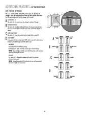
After the adjustments are made the Save switch must be in order for single gate installation. For Dual (Gate 1 and 2) installation set switch on Dual Mode. 3 Set the Save switch to the ON position. 2 OFF OFF SINGLE NO NO OFF...4 5 N O1 2 3 4 5 N O1 2 3 4 5 N O1 2 3 4 5 N OFF OFF SINGLE NO NO ON SAVE ON MAGLOCK DUAL MODE NC EDGE NC PHOTO S1 O1 2 3 4 5 N OFF OFF SINGLE NO NO ON SAVE ON MAGLOCK... DUAL MODE NC EDGE NC PHOTO S1 ON ON DUAL MODE NC NC ON ON DUAL MODE NC NC ON SAVE ON DUAL MODE NC NC GATE 1 GATE 1 AND GATE 2 29 ADJUSTMENT...
After the adjustments are made the Save switch must be in order for single gate installation. For Dual (Gate 1 and 2) installation set switch on Dual Mode. 3 Set the Save switch to the ON position. 2 OFF OFF SINGLE NO NO OFF...4 5 N O1 2 3 4 5 N O1 2 3 4 5 N O1 2 3 4 5 N OFF OFF SINGLE NO NO ON SAVE ON MAGLOCK DUAL MODE NC EDGE NC PHOTO S1 O1 2 3 4 5 N OFF OFF SINGLE NO NO ON SAVE ON MAGLOCK... DUAL MODE NC EDGE NC PHOTO S1 ON ON DUAL MODE NC NC ON ON DUAL MODE NC NC ON SAVE ON DUAL MODE NC NC GATE 1 GATE 1 AND GATE 2 29 ADJUSTMENT...
LA400 Manual
Page 32
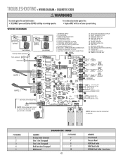
SET CLOSE LIMIT LE LIMIT GATE 2 FORCE 8 Press the GATE 1 left operator. DUAL GATE (LEFT-SIDE PRIMARY OPERATOR) 1 Close the gate. 2 Engage the operator by pressing the SBC to open and close the left button to close the ...
SET CLOSE LIMIT LE LIMIT GATE 2 FORCE 8 Press the GATE 1 left operator. DUAL GATE (LEFT-SIDE PRIMARY OPERATOR) 1 Close the gate. 2 Engage the operator by pressing the SBC to open and close the left button to close the ...

LA400 Manual
Page 33
... the GATE 1 left button to GATE 1 so it will beep. SET CLOSE LIMIT LE LIMITS 6 Press the LEARN LIMITS SET SET GATE 2 OPEN CLOSE button. DUAL GATE (RIGHT-SIDE PRIMARY OPERATOR) 1 Close the gate. 2 Engage the operator by pressing the RESET button. Control LIMIT LIMIT FORCE board will start moving before...
... the GATE 1 left button to GATE 1 so it will beep. SET CLOSE LIMIT LE LIMITS 6 Press the LEARN LIMITS SET SET GATE 2 OPEN CLOSE button. DUAL GATE (RIGHT-SIDE PRIMARY OPERATOR) 1 Close the gate. 2 Engage the operator by pressing the RESET button. Control LIMIT LIMIT FORCE board will start moving before...
LA400 Manual
Page 36
...terminals. D SAFETY INPUTS Swing gates allow the Maglock to be set in N/O mode (See Accessories). OFF OFF SINGLE NO NO ON SAVE ON MAGLOCK DUAL MODE NC EDGE NC PHOTO S1 A SAVE OFF B OFF MAGLOCK OFF OFF C OFF SINGLE NO NO OFF OFF EDGE NO D OFF OFF PHOTO NO... changes to release. B MAG DELAY ENABLE This switch (S1-2) enables the Maglock feature. On an open command there will automatically learn in the N/O position, as Dual or Single (Refer to save the settings for switches 2 through 5. EYE INPUT This switch (S1-5) differentiates between N/O and N/C edges and N/O and N/C eyes. ...
...terminals. D SAFETY INPUTS Swing gates allow the Maglock to be set in N/O mode (See Accessories). OFF OFF SINGLE NO NO ON SAVE ON MAGLOCK DUAL MODE NC EDGE NC PHOTO S1 A SAVE OFF B OFF MAGLOCK OFF OFF C OFF SINGLE NO NO OFF OFF EDGE NO D OFF OFF PHOTO NO... changes to release. B MAG DELAY ENABLE This switch (S1-2) enables the Maglock feature. On an open command there will automatically learn in the N/O position, as Dual or Single (Refer to save the settings for switches 2 through 5. EYE INPUT This switch (S1-5) differentiates between N/O and N/C edges and N/O and N/C eyes. ...

LA400 Manual
Page 39
...accessory power, 150 mA switched accessory power. • 24 V power to meet the requirements of UL325 and UL991. Secure the control box cover with the LA400 to control box depending on three sides. (Requires mounting channel. Sensitized on wire gauge and distance - 300 mA accessory power, 75 mA switched accessory power...Ø14LGØ89ØE Ø14SKØ89ØE J 1 K5 L1 1 S8 R2 OFF OFF ON SAVE ON MAGLOCK LEARN R1 XMITTER SINGLE NO DUAL MODE NC EDGE 2 F3 NO NC PHOTO S1 K2 DIAGNOSTIC GATE 1 K1 Q9 SET OPEN LIMIT SET CLOSE LIMIT LEARN LIMITS R2Ø7 Z2Ø...
...accessory power, 150 mA switched accessory power. • 24 V power to meet the requirements of UL325 and UL991. Secure the control box cover with the LA400 to control box depending on three sides. (Requires mounting channel. Sensitized on wire gauge and distance - 300 mA accessory power, 75 mA switched accessory power...Ø14LGØ89ØE Ø14SKØ89ØE J 1 K5 L1 1 S8 R2 OFF OFF ON SAVE ON MAGLOCK LEARN R1 XMITTER SINGLE NO DUAL MODE NC EDGE 2 F3 NO NC PHOTO S1 K2 DIAGNOSTIC GATE 1 K1 Q9 SET OPEN LIMIT SET CLOSE LIMIT LEARN LIMITS R2Ø7 Z2Ø...

LA400 Manual
Page 42
...;E Ø14LGØ89ØE Ø14SKØ89ØE J 1 K5 L1 1 S8 R2 OFF OFF ON SAVE ON MAGLOCK LEARN R1 XMITTER SINGLE NO DUAL MODE NC EDGE 2 F3 NO NC PHOTO S1 K2 DIAGNOSTIC GATE 1 K1 Q9 SET OPEN LIMIT SET CLOSE LIMIT LEARN LIMITS R2Ø7 Z2Ø...
...;E Ø14LGØ89ØE Ø14SKØ89ØE J 1 K5 L1 1 S8 R2 OFF OFF ON SAVE ON MAGLOCK LEARN R1 XMITTER SINGLE NO DUAL MODE NC EDGE 2 F3 NO NC PHOTO S1 K2 DIAGNOSTIC GATE 1 K1 Q9 SET OPEN LIMIT SET CLOSE LIMIT LEARN LIMITS R2Ø7 Z2Ø...
LA400 Manual
Page 43
... GRN 10A 32V D1ÿ WHT YEL BLU RED Z12 J19 K6 K5 L1 17 1 S8 R2 OFF OFF ON SAVE ON MAGLOCK LEARN SINGLE DUAL MODE R1 XMITTER NO NC EDGE NO NC PHOTO 2 S1 F3 K2 18 19 DIAGNOSTIC K1 Q9 SET OPEN LIMIT 20 GATE 1 SET CLOSE LIMIT...
... GRN 10A 32V D1ÿ WHT YEL BLU RED Z12 J19 K6 K5 L1 17 1 S8 R2 OFF OFF ON SAVE ON MAGLOCK LEARN SINGLE DUAL MODE R1 XMITTER NO NC EDGE NO NC PHOTO 2 S1 F3 K2 18 19 DIAGNOSTIC K1 Q9 SET OPEN LIMIT 20 GATE 1 SET CLOSE LIMIT...


