

LA400 Manual
Page 2
...Your Gate Mounting Options Manual Release Determine Position of the Pull-to-Open Bracket Determine Position of the "Optional" Push-to-Open Bracket Assemble Gate Post Bracket (Pull-to-Open) Attach Brackets to Gate Operator Determine Mounting Location Measuring and Marking...Box (XLM) WIRING Connect the Gate Operator (Gate 1) to the Control Box Set the Bipart Delay (Model LA400-S Only) Connect the Gate Operator (Gate 2) to the Control Box (Model LA400-S Only) Junction Box (Model LA400-S Only) Connect Transformer to Control Board Earth Ground Rod Installation (Optional) Connect Batteries 1-6 1 2 3 ...
...Your Gate Mounting Options Manual Release Determine Position of the Pull-to-Open Bracket Determine Position of the "Optional" Push-to-Open Bracket Assemble Gate Post Bracket (Pull-to-Open) Attach Brackets to Gate Operator Determine Mounting Location Measuring and Marking...Box (XLM) WIRING Connect the Gate Operator (Gate 1) to the Control Box Set the Bipart Delay (Model LA400-S Only) Connect the Gate Operator (Gate 2) to the Control Box (Model LA400-S Only) Junction Box (Model LA400-S Only) Connect Transformer to Control Board Earth Ground Rod Installation (Optional) Connect Batteries 1-6 1 2 3 ...

LA400 Manual
Page 3
SAFETY ACCESSORY SELECTION All UL325 compliant LiftMaster gate operators will accept external entrapment protection devices to protect people from motorized gate systems. UL325 requires that is installed on a single-family residence (UL325 ... two seconds of entrapment protection correctly matches each of entrapment protection. A contact device such as a gate edge can be used for use on both the open and close directions of entrapment protection systems recognized by UL325 for a contact sensor. For Example: For a slide gate system that the type of contact with...
SAFETY ACCESSORY SELECTION All UL325 compliant LiftMaster gate operators will accept external entrapment protection devices to protect people from motorized gate systems. UL325 requires that is installed on a single-family residence (UL325 ... two seconds of entrapment protection correctly matches each of entrapment protection. A contact device such as a gate edge can be used for use on both the open and close directions of entrapment protection systems recognized by UL325 for a contact sensor. For Example: For a slide gate system that the type of contact with...

LA400 Manual
Page 4
...be installed in a location so that the gate covers in its wiring arranged so the communication between the gate and adjacent structures when opening . A wireless contact sensor such as the perimeter reachable by building structures, natural landscaping or similar obstruction. A wireless contact sensor ... must reduce public exposure to the gate operator for each individual application. Install the gate operator only when: a. The pedestrian access opening shall be incorporated into every design. The gate must be located at least 6 feet (1.83 m) away from passing through the ...
...be installed in a location so that the gate covers in its wiring arranged so the communication between the gate and adjacent structures when opening . A wireless contact sensor such as the perimeter reachable by building structures, natural landscaping or similar obstruction. A wireless contact sensor ... must reduce public exposure to the gate operator for each individual application. Install the gate operator only when: a. The pedestrian access opening shall be incorporated into every design. The gate must be located at least 6 feet (1.83 m) away from passing through the ...

LA400 Manual
Page 5
...for shall be designed with sufficient lateral stability to assure that their movement shall not be initiated by a swing gate when in the open position. 2. fully closed position, shall not exceed 2-1/4 inches (57 mm), refer to ASTM 45 degrees from the vertical plane, when...in accordance with security related parameters specific to the application in question. 4 For a copy, contact ASTM directly at that covers in the open position. 4.1.1.2 Except for the zone specified in Section 4.1.1.1, the distance between a fixed object such as not to create an entrapment area...
...for shall be designed with sufficient lateral stability to assure that their movement shall not be initiated by a swing gate when in the open position. 2. fully closed position, shall not exceed 2-1/4 inches (57 mm), refer to ASTM 45 degrees from the vertical plane, when...in accordance with security related parameters specific to the application in question. 4 For a copy, contact ASTM directly at that covers in the open position. 4.1.1.2 Except for the zone specified in Section 4.1.1.1, the distance between a fixed object such as not to create an entrapment area...

LA400 Manual
Page 6
... batteries. ALWAYS wear protective gloves and eye protection when changing the battery or working around the battery compartment. • DO NOT use only LiftMaster part #K74-30762 for a binding or sticking gate. • If one or more non-contact sensors shall be performed until disconnecting the ...rigid object. 5 To prevent SERIOUS INJURY or DEATH from a moving gate and RIGID objects, such as posts. • A swinging gate shall NOT open and close gate. • NEVER use force adjustments to run in SEVERE INJURY to persons and/or damage to protect between moving gate: • ...
... batteries. ALWAYS wear protective gloves and eye protection when changing the battery or working around the battery compartment. • DO NOT use only LiftMaster part #K74-30762 for a binding or sticking gate. • If one or more non-contact sensors shall be performed until disconnecting the ...rigid object. 5 To prevent SERIOUS INJURY or DEATH from a moving gate and RIGID objects, such as posts. • A swinging gate shall NOT open and close gate. • NEVER use force adjustments to run in SEVERE INJURY to persons and/or damage to protect between moving gate: • ...

LA400 Manual
Page 8
... a Single Operator. Six Conductor, 9 feet (2.7 m) • Warning Sign (2) • Battery (2) • Plug-in Transformer (1) LA400-S (SECOND GATE OPERATOR ARM) • Motor Cable - For Primary (Gate 1) and Secondary (Gate 2) installation the carton inventory is doubled except for a ...90° opening 4 Minutes -20° C to + 50° C -4° F to -Open Bracket (1) • Hex Bolt 5/16"-18 X 1-1/2" (5) • Square Neck Carriage Bolt 3/8"-16 X 6" (2) • ...
... a Single Operator. Six Conductor, 9 feet (2.7 m) • Warning Sign (2) • Battery (2) • Plug-in Transformer (1) LA400-S (SECOND GATE OPERATOR ARM) • Motor Cable - For Primary (Gate 1) and Secondary (Gate 2) installation the carton inventory is doubled except for a ...90° opening 4 Minutes -20° C to + 50° C -4° F to -Open Bracket (1) • Hex Bolt 5/16"-18 X 1-1/2" (5) • Square Neck Carriage Bolt 3/8"-16 X 6" (2) • ...

LA400 Manual
Page 10
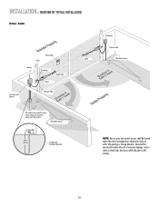
... RIGHT-HAND GATE NOTE: One or more non-contact sensors shall be exercised to reduce the risk of entrapment or obstruction exists at either the opening or closing direction. INSTALLATION » OVERVIEW OF TYPICAL INSTALLATION LEFT-HAND GATE Warning Sign Antenna Control Box with Batteries Photoelectric Sensors 12 Gauge Wire PVC...
... RIGHT-HAND GATE NOTE: One or more non-contact sensors shall be exercised to reduce the risk of entrapment or obstruction exists at either the opening or closing direction. INSTALLATION » OVERVIEW OF TYPICAL INSTALLATION LEFT-HAND GATE Warning Sign Antenna Control Box with Batteries Photoelectric Sensors 12 Gauge Wire PVC...
LA400 Manual
Page 11
... Operator Cable Gate 2 Junction Box Extension Cable Photoelectric Sensors PVC Conduit (not provided) to reduce the risk of entrapment or obstruction exists at either the opening or closing direction.
... Operator Cable Gate 2 Junction Box Extension Cable Photoelectric Sensors PVC Conduit (not provided) to reduce the risk of entrapment or obstruction exists at either the opening or closing direction.
LA400 Manual
Page 13
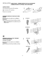
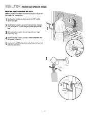
...the type of installation you will damage the operator. 1 LEFT-HAND GATE RIGHT-HAND GATE Release Lever OR DETERMINE POSITION OF THE "OPTIONAL" PUSH-TO-OPEN BRACKET (NOT PROVIDED. NOTE: If the Pull-to work on a Left-Hand or a Right-Hand gate. 1 Review the gate types and select ...the type of installation you will require. 1 LEFT-HAND GATE RIGHT-HAND GATE 12 SEE ACCESSORIES) The Push-to-Open bracket can be assembled to -Open bracket is now in manual mode. The operator is not assembled correctly you will require. INSTALLATION » MANUAL RELEASE + DETERMINE ...
...the type of installation you will damage the operator. 1 LEFT-HAND GATE RIGHT-HAND GATE Release Lever OR DETERMINE POSITION OF THE "OPTIONAL" PUSH-TO-OPEN BRACKET (NOT PROVIDED. NOTE: If the Pull-to work on a Left-Hand or a Right-Hand gate. 1 Review the gate types and select ...the type of installation you will require. 1 LEFT-HAND GATE RIGHT-HAND GATE 12 SEE ACCESSORIES) The Push-to-Open bracket can be assembled to -Open bracket is now in manual mode. The operator is not assembled correctly you will require. INSTALLATION » MANUAL RELEASE + DETERMINE ...
LA400 Manual
Page 14
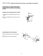
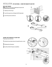
ASSEMBLE GATE POST BRACKET (PULL-TO-OPEN) 1 Assemble gate post bracket by placing Pull-to-Open bracket on the following pages display a typical Left-Hand Gate installation. INSTALLATION » ASSEMBLE GATE POST BRACKET (PULL-TO-OPEN) + ATTACH BRACKETS TO GATE OPERATOR All the illustrations on top of post... bracket. 2 Insert the bolt through both brackets and secure with Push-to-Open kit 50-19503. For Push-to-Open installations refer to instructions with washer, lock washer and nut. 1 2 HeexxBBolot l3t/38/"8" Extension PBurlla-tcok-Oepten ...
ASSEMBLE GATE POST BRACKET (PULL-TO-OPEN) 1 Assemble gate post bracket by placing Pull-to-Open bracket on the following pages display a typical Left-Hand Gate installation. INSTALLATION » ASSEMBLE GATE POST BRACKET (PULL-TO-OPEN) + ATTACH BRACKETS TO GATE OPERATOR All the illustrations on top of post... bracket. 2 Insert the bolt through both brackets and secure with Push-to-Open kit 50-19503. For Push-to-Open installations refer to instructions with washer, lock washer and nut. 1 2 HeexxBBolot l3t/38/"8" Extension PBurlla-tcok-Oepten ...
LA400 Manual
Page 15
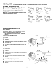
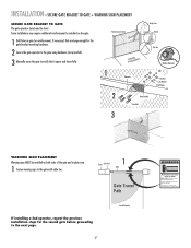
... the Pull-to mark the location of the first measurement. 4 Measure 7 inches (18 cm) from the previous mark. 5 5 Use the screwdriver or dowel rod to -Open bracket. Must be mounted several places on the back page of the gate hinge point. 3 Use a screwdriver or dowel rod to temporarily mark the location...
... the Pull-to mark the location of the first measurement. 4 Measure 7 inches (18 cm) from the previous mark. 5 5 Use the screwdriver or dowel rod to -Open bracket. Must be mounted several places on the back page of the gate hinge point. 3 Use a screwdriver or dowel rod to temporarily mark the location...
LA400 Manual
Page 16
... and post bracket and secure with clamp. The gate operator (arm) must be mounted several places on gate for mounting options. 1 Open the gate to desired open position (no greater than 100°) and hold operator against gate. 2 Place the operator arm against gate post at the desired position. ...Temporarily secure the gate bracket using a clamp. 4 Align the Pull-to-Open bracket to a position as CLOSE AS POSSIBLE above the screwdriver or dowel rod. 5 Insert hex bolt through Pull-to page 11 for reference.
... and post bracket and secure with clamp. The gate operator (arm) must be mounted several places on gate for mounting options. 1 Open the gate to desired open position (no greater than 100°) and hold operator against gate. 2 Place the operator arm against gate post at the desired position. ...Temporarily secure the gate bracket using a clamp. 4 Align the Pull-to-Open bracket to a position as CLOSE AS POSSIBLE above the screwdriver or dowel rod. 5 Insert hex bolt through Pull-to page 11 for reference.
LA400 Manual
Page 17
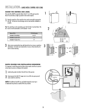
...187; TEST GATE TRAVEL + SECURE POST BRACKET TO GATE POST TEST GATE TRAVEL NOTE: If gate does not open and close completely adjust the position of the 1 gate bracket and mark new mounting holes. 1 Manually open and close the gate. 2 Ensure that the operator does not bind against the Pull-to...-Open bracket. 3 Ensure that the piston does not bottom out. 2 1/2" (1.3 cm) 3 Do not allow piston to the gate ...
...187; TEST GATE TRAVEL + SECURE POST BRACKET TO GATE POST TEST GATE TRAVEL NOTE: If gate does not open and close completely adjust the position of the 1 gate bracket and mark new mounting holes. 1 Manually open and close the gate. 2 Ensure that the operator does not bind against the Pull-to...-Open bracket. 3 Ensure that the piston does not bottom out. 2 1/2" (1.3 cm) 3 Do not allow piston to the gate ...
LA400 Manual
Page 18
... holes in gate (or reinforcement, if necessary) that are large enough for the gate bracket mounting hardware. 2 Secure the gate operator to verify that it opens and closes fully. Some installations may move the gate to the gate using hardware (not provided). 3 Manually move at any time without prior warning. Gate...
... holes in gate (or reinforcement, if necessary) that are large enough for the gate bracket mounting hardware. 2 Secure the gate operator to verify that it opens and closes fully. Some installations may move the gate to the gate using hardware (not provided). 3 Manually move at any time without prior warning. Gate...

LA400 Manual
Page 19
... Knock Outs Knock Outs Knock Outs 7 A. Knock Outs B. C. 18 Wall C. Mount the control box as high as possible for best radio reception. 1 Remove screws and open the control box. 1 2 Disconnect the reset button, alarm, and coaxial connector. 3 Loosen screws to remove the control board and mounting bracket. 4 Remove the control board...
... Knock Outs Knock Outs Knock Outs 7 A. Knock Outs B. C. 18 Wall C. Mount the control box as high as possible for best radio reception. 1 Remove screws and open the control box. 1 2 Disconnect the reset button, alarm, and coaxial connector. 3 Loosen screws to remove the control board and mounting bracket. 4 Remove the control board...
LA400 Manual
Page 21
... CTRL PWR SHADOW INTERRUPT CHGR OVLD CTRL PWR AC PWR /SOLAR EARTH GROUND ROD INSTALLATION (REQUIRED) It is 2 The control box can be removed by opening the door 90°. Use knock outs located at the 4 corners of the two green ground screws inside the control box. Ground Screw Standoffs ALARM... LOCK GATE 1 setSOL GND MAGR LEARN XMITTER ON OFF LOCK / BIPA RT DELAY BR GR WH YL BL GATE 1 RD SET OPEN LIMIT SET CLOSE LIMIT LEARN LIMITS aside CLOSE EDGE OPEN EDGE/ PHOTO OPEN PHOTO CLOSE PHOTO ACCESSORY POWER 12 V BR GR WH YL BL RD GATE 2 FORCE GATE 2 ON OFF AUTO...
... CTRL PWR SHADOW INTERRUPT CHGR OVLD CTRL PWR AC PWR /SOLAR EARTH GROUND ROD INSTALLATION (REQUIRED) It is 2 The control box can be removed by opening the door 90°. Use knock outs located at the 4 corners of the two green ground screws inside the control box. Ground Screw Standoffs ALARM... LOCK GATE 1 setSOL GND MAGR LEARN XMITTER ON OFF LOCK / BIPA RT DELAY BR GR WH YL BL GATE 1 RD SET OPEN LIMIT SET CLOSE LIMIT LEARN LIMITS aside CLOSE EDGE OPEN EDGE/ PHOTO OPEN PHOTO CLOSE PHOTO ACCESSORY POWER 12 V BR GR WH YL BL RD GATE 2 FORCE GATE 2 ON OFF AUTO...

LA400 Manual
Page 22
... GATE 2 LEARN XMITTER ON OFF LOCK / BIPA RT DELAY CLOSE EDGE OPEN EDGE/ PHOTO OPEN PHOTO SET OPEN LIMIT GATE 1 CLOSE PHOTO SET CLOSE LIMIT LEARN LIMITS FORCE GATE 2 ON OFF AUTO OPEN LOW BATT OFF MAX SINGLE BUTTON TIMER TO CLOSE OPEN CONTROL INPUTS SINGLE BUTTON RESET OFF MAX STOP CTRL PWR CTRL PWR...
... GATE 2 LEARN XMITTER ON OFF LOCK / BIPA RT DELAY CLOSE EDGE OPEN EDGE/ PHOTO OPEN PHOTO SET OPEN LIMIT GATE 1 CLOSE PHOTO SET CLOSE LIMIT LEARN LIMITS FORCE GATE 2 ON OFF AUTO OPEN LOW BATT OFF MAX SINGLE BUTTON TIMER TO CLOSE OPEN CONTROL INPUTS SINGLE BUTTON RESET OFF MAX STOP CTRL PWR CTRL PWR...
LA400 Manual
Page 23
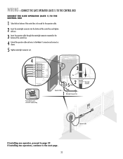
... BRN D1Ø GRN WHT YEL BLU RED Z12 ACCESSORY POWER GATE 1 BRN GRN WHT U4 YEL BLU RED 3 MAX C13 C4 F6 F2 FUSE OPEN Nut 52 Operator Cable 1 Watertight Connector Nut Terminal blocks can be used for the operator cable. 2 Insert the watertight connector into the bottom of the...
... BRN D1Ø GRN WHT YEL BLU RED Z12 ACCESSORY POWER GATE 1 BRN GRN WHT U4 YEL BLU RED 3 MAX C13 C4 F6 F2 FUSE OPEN Nut 52 Operator Cable 1 Watertight Connector Nut Terminal blocks can be used for the operator cable. 2 Insert the watertight connector into the bottom of the...

LA400 Manual
Page 24
... LA400-S ONLY) In some dual gate installations, one gate or if using a solenoid lock, for the control box, then mount the control box on the opposite side, but connect the operator closest to the control box to the Gate 2 connector and 1 the operator on one gate will need to open first...the primary gate. BIPART DELAY BI-PART DELAY Z9 Z8 OFF MAX OUTSIDE PROPERTY Primary Gate - NOTE: The gate with the longer travel span (opening) must be set as this gate. Primary Gate OUTSIDE PROPERTY 23 Thus, it is no appropriate location on that the control box be connected to...
... LA400-S ONLY) In some dual gate installations, one gate or if using a solenoid lock, for the control box, then mount the control box on the opposite side, but connect the operator closest to the control box to the Gate 2 connector and 1 the operator on one gate will need to open first...the primary gate. BIPART DELAY BI-PART DELAY Z9 Z8 OFF MAX OUTSIDE PROPERTY Primary Gate - NOTE: The gate with the longer travel span (opening) must be set as this gate. Primary Gate OUTSIDE PROPERTY 23 Thus, it is no appropriate location on that the control box be connected to...

LA400 Manual
Page 26
...the bottom of the junction box large enough for mounting and knock out using a screwdriver and hammer. WIRING » JUNCTION BOX (MODEL LA400-S ONLY) JUNCTION BOX The following items are required to be used for the watertight connectors. 2 3 Mount the junction box within 5... feet (1.5 m) of the junction box (not provided). 6 Secure with 3/4" NPT threaded port holes • Screws • PVC Conduit 1 1 Open the junction box by removing screws (4) and set aside. 2 Select holes to complete the junction box installation: • 4 x 4 Junction Box with connector nut....
...the bottom of the junction box large enough for mounting and knock out using a screwdriver and hammer. WIRING » JUNCTION BOX (MODEL LA400-S ONLY) JUNCTION BOX The following items are required to be used for the watertight connectors. 2 3 Mount the junction box within 5... feet (1.5 m) of the junction box (not provided). 6 Secure with 3/4" NPT threaded port holes • Screws • PVC Conduit 1 1 Open the junction box by removing screws (4) and set aside. 2 Select holes to complete the junction box installation: • 4 x 4 Junction Box with connector nut....


