
LA400 Manual
Page 11
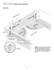
.... 10 INSTALLATION » OVERVIEW OF TYPICAL INSTALLATION DUAL GATE Warning Sign Hinge Antenna Post Bracket Gate Bracket Gate 1 Control Box with Batteries Operator Cable Gate 2 Junction Box Extension Cable Photoelectric Sensors PVC Conduit (not provided) to reduce the risk of entrapment or obstruction exists at either the opening or closing direction. Photoelectric Sensors 12 Gauge Wire...
.... 10 INSTALLATION » OVERVIEW OF TYPICAL INSTALLATION DUAL GATE Warning Sign Hinge Antenna Post Bracket Gate Bracket Gate 1 Control Box with Batteries Operator Cable Gate 2 Junction Box Extension Cable Photoelectric Sensors PVC Conduit (not provided) to reduce the risk of entrapment or obstruction exists at either the opening or closing direction. Photoelectric Sensors 12 Gauge Wire...

LA400 Manual
Page 24
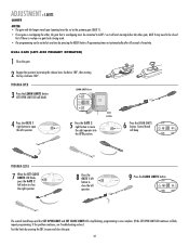
... (MODEL LA400-S ONLY) SET THE BIPART DELAY (MODEL LA400-S ONLY) In some dual gate installations, one gate or if using a solenoid lock, for the control box, then mount the control box on the opposite side, but connect the operator closest to the control box to the Gate 2 connector...DELAY BI-PART DELAY Z9 Z8 OFF MAX OUTSIDE PROPERTY Primary Gate - The following illustration shows a dual gate configuration with the lock attached to open first and close second. NOTE: The gate with the longer travel span (opening) must be installed on the control board. This would happen...
... (MODEL LA400-S ONLY) SET THE BIPART DELAY (MODEL LA400-S ONLY) In some dual gate installations, one gate or if using a solenoid lock, for the control box, then mount the control box on the opposite side, but connect the operator closest to the control box to the Gate 2 connector...DELAY BI-PART DELAY Z9 Z8 OFF MAX OUTSIDE PROPERTY Primary Gate - The following illustration shows a dual gate configuration with the lock attached to open first and close second. NOTE: The gate with the longer travel span (opening) must be installed on the control board. This would happen...
LA400 Manual
Page 32
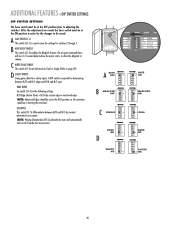
... CLOSE LIMIT LE LIMITS Press the LEARN LIMITS button. DIAGNOSTIC GATE 1 SET CLOSE 5 Press the GATE 2 right button to blink, repeat programming. DUAL GATE (LEFT-SIDE PRIMARY OPERATOR) 1 Close the gate. 2 Engage the operator by pressing the SBC to open the left operator. LEARN LIMITS button SET OPEN LIMIT R2 K2 U4 D4 D2 RESET BUTTON 4 Press...
... CLOSE LIMIT LE LIMITS Press the LEARN LIMITS button. DIAGNOSTIC GATE 1 SET CLOSE 5 Press the GATE 2 right button to blink, repeat programming. DUAL GATE (LEFT-SIDE PRIMARY OPERATOR) 1 Close the gate. 2 Engage the operator by pressing the SBC to open the left operator. LEARN LIMITS button SET OPEN LIMIT R2 K2 U4 D4 D2 RESET BUTTON 4 Press...

LA400 Manual
Page 33
... to blink, repeat programming. DIAGNOSTIC 9 Press the LEARN LIMITS SET GATE 1 button. DUAL GATE (RIGHT-SIDE PRIMARY OPERATOR) 1 Close the gate. 2 Engage the operator by pressing the RESET button. LEARN LIMITS button SET OPEN LIMIT R2 K2 U4 D4 D2 RESET BUTTON 4 Press the GATE 1 left button to be closed first if there is overlap or...
... to blink, repeat programming. DIAGNOSTIC 9 Press the LEARN LIMITS SET GATE 1 button. DUAL GATE (RIGHT-SIDE PRIMARY OPERATOR) 1 Close the gate. 2 Engage the operator by pressing the RESET button. LEARN LIMITS button SET OPEN LIMIT R2 K2 U4 D4 D2 RESET BUTTON 4 Press the GATE 1 left button to be closed first if there is overlap or...
LA400 Manual
Page 36
...DELAY ENABLE This switch (S1-2) enables the Maglock feature. On an open command there will automatically learn in N/O mode (See Accessories). EDGE... be a 1/2 second delay before the motor starts, to allow four safety inputs. D SAFETY INPUTS Swing gates allow the Maglock to adjusting the switches. After the adjustments are made the Save switch must be in the...dry contact edge or monitored edge NOTE: Monitored Edges should be set in the N/O position, as Dual or Single (Refer to save the settings for determining between N/O and N/C dry contact photoelectric eye inputs. A...
...DELAY ENABLE This switch (S1-2) enables the Maglock feature. On an open command there will automatically learn in N/O mode (See Accessories). EDGE... be a 1/2 second delay before the motor starts, to allow four safety inputs. D SAFETY INPUTS Swing gates allow the Maglock to adjusting the switches. After the adjustments are made the Save switch must be in the...dry contact edge or monitored edge NOTE: Monitored Edges should be set in the N/O position, as Dual or Single (Refer to save the settings for determining between N/O and N/C dry contact photoelectric eye inputs. A...

LA400 Manual
Page 39
...;E J 1 K5 L1 1 S8 R2 OFF OFF ON SAVE ON MAGLOCK LEARN R1 XMITTER SINGLE NO DUAL MODE NC EDGE 2 F3 NO NC PHOTO S1 K2 DIAGNOSTIC GATE 1 K1 Q9 SET OPEN LIMIT SET CLOSE LIMIT LEARN LIMITS R2Ø7 Z2Ø R227 J18 U4 R224 Z22 R92 R91 R94...RN4 MODEL G65MG0204 G65MG0205 G65MGR205 G65MGS205 PHOTOELECTRIC CONTROLS DESCRIPTION Emitter, receiver and mounting brackets - 30 feet (9 m) Ranges VOLTAGE +24 Vdc Emitter with the LA400 to control box depending on wire gauge and distance - 300 mA accessory power, 75 mA switched accessory power. PIN:G65ME120C5) Miller MG020 2-wire ...
...;E J 1 K5 L1 1 S8 R2 OFF OFF ON SAVE ON MAGLOCK LEARN R1 XMITTER SINGLE NO DUAL MODE NC EDGE 2 F3 NO NC PHOTO S1 K2 DIAGNOSTIC GATE 1 K1 Q9 SET OPEN LIMIT SET CLOSE LIMIT LEARN LIMITS R2Ø7 Z2Ø R227 J18 U4 R224 Z22 R92 R91 R94...RN4 MODEL G65MG0204 G65MG0205 G65MGR205 G65MGS205 PHOTOELECTRIC CONTROLS DESCRIPTION Emitter, receiver and mounting brackets - 30 feet (9 m) Ranges VOLTAGE +24 Vdc Emitter with the LA400 to control box depending on wire gauge and distance - 300 mA accessory power, 75 mA switched accessory power. PIN:G65ME120C5) Miller MG020 2-wire ...

LA400 Manual
Page 42
...216;E J 1 K5 L1 1 S8 R2 OFF OFF ON SAVE ON MAGLOCK LEARN R1 XMITTER SINGLE NO DUAL MODE NC EDGE 2 F3 NO NC PHOTO S1 K2 DIAGNOSTIC GATE 1 K1 Q9 SET OPEN LIMIT SET CLOSE LIMIT LEARN LIMITS R2Ø7 Z2Ø R227 J18 R224 U4 Z22 R92 R91 R94 R93...Connector P16 11 Connector P13 12 Connector P17 13 Connector P14 FUNCTION Antenna Input Close Edge Open Edge/Photo Open Photo Close Photo Switched Accessory Power* Control Inputs Loop Inputs 24 Vac Input Gate 2 Accessory Power* Gate 1 Maglock/Solenoid *See page 38 for max current draw ITEM DESCRIPTION 14 Connector P15 ...
...216;E J 1 K5 L1 1 S8 R2 OFF OFF ON SAVE ON MAGLOCK LEARN R1 XMITTER SINGLE NO DUAL MODE NC EDGE 2 F3 NO NC PHOTO S1 K2 DIAGNOSTIC GATE 1 K1 Q9 SET OPEN LIMIT SET CLOSE LIMIT LEARN LIMITS R2Ø7 Z2Ø R227 J18 R224 U4 Z22 R92 R91 R94 R93...Connector P16 11 Connector P13 12 Connector P17 13 Connector P14 FUNCTION Antenna Input Close Edge Open Edge/Photo Open Photo Close Photo Switched Accessory Power* Control Inputs Loop Inputs 24 Vac Input Gate 2 Accessory Power* Gate 1 Maglock/Solenoid *See page 38 for max current draw ITEM DESCRIPTION 14 Connector P15 ...
LA400 Manual
Page 43
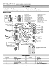
... K6 K5 L1 17 1 S8 R2 OFF OFF ON SAVE ON MAGLOCK LEARN SINGLE DUAL MODE R1 XMITTER NO NC EDGE NO NC PHOTO 2 S1 F3 K2 18 19 DIAGNOSTIC K1 Q9 SET OPEN LIMIT 20 GATE 1 SET CLOSE LIMIT LEARN LIMITS R2ÿ 7 Z2ÿ R227 J18 R224... • DISCONNECT power and battery BEFORE installing or servicing operator. FAULT ALARM OUTPUT 15. DIP SWITCH, S1 18. OPEN EDGE/PHOTO EYE 4. LEARN XMITTER 19. OPEN PHOTO EYE 5. TRANSFORMER INPUT 10. SECOND GATE JOG 22. BATTERY INPUT #2 17. CLOSE PHOTO EYE 6. 24VDC ACCESSORY OUTPUT 7. MAGLOCK/SOLENOID OUTPUT 14. CLOSE EDGE...
... K6 K5 L1 17 1 S8 R2 OFF OFF ON SAVE ON MAGLOCK LEARN SINGLE DUAL MODE R1 XMITTER NO NC EDGE NO NC PHOTO 2 S1 F3 K2 18 19 DIAGNOSTIC K1 Q9 SET OPEN LIMIT 20 GATE 1 SET CLOSE LIMIT LEARN LIMITS R2ÿ 7 Z2ÿ R227 J18 R224... • DISCONNECT power and battery BEFORE installing or servicing operator. FAULT ALARM OUTPUT 15. DIP SWITCH, S1 18. OPEN EDGE/PHOTO EYE 4. LEARN XMITTER 19. OPEN PHOTO EYE 5. TRANSFORMER INPUT 10. SECOND GATE JOG 22. BATTERY INPUT #2 17. CLOSE PHOTO EYE 6. 24VDC ACCESSORY OUTPUT 7. MAGLOCK/SOLENOID OUTPUT 14. CLOSE EDGE...


