8550 Manual
Page 1
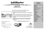
...sectional doors. Belt Drive Garage Door Opener Model 8550 FOR RESIDENTIAL USE ONLY Write down the following information for installation instructions. . www.liftmaster.com The Chamberlain Group, Inc. 845 Larch Avenue Elmhurst, Illinois 60126-1196 Contents BELT DRIVE GARAGE DOOR OPENER.. 1 PREPARATION 2 ASSEMBLY 4 INSTALLATION... 35-36 REPAIR PARTS 37-38 ACCESSORIES 39 WARRANTY 40 NOTE: If you are installing the garage door opener on a one -piece door, visit www.liftmaster.com for future reference: Serial Number: Date of Purchase: ■ Please read this manual and the ...
...sectional doors. Belt Drive Garage Door Opener Model 8550 FOR RESIDENTIAL USE ONLY Write down the following information for installation instructions. . www.liftmaster.com The Chamberlain Group, Inc. 845 Larch Avenue Elmhurst, Illinois 60126-1196 Contents BELT DRIVE GARAGE DOOR OPENER.. 1 PREPARATION 2 ASSEMBLY 4 INSTALLATION... 35-36 REPAIR PARTS 37-38 ACCESSORIES 39 WARRANTY 40 NOTE: If you are installing the garage door opener on a one -piece door, visit www.liftmaster.com for future reference: Serial Number: Date of Purchase: ■ Please read this manual and the ...
8550 Manual
Page 2
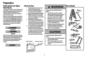
...and Signal Words on the bottom of the door. Read the warnings carefully. Raise and lower the door to the garage door. 2. The opener should stay in place, supported entirely by its springs. 3. If there is out of balance. Check the seal on the following pages, it... possible SERIOUS INJURY or DEATH: • ALWAYS call a trained door systems technician. 4. Preparation Safety Symbol and Signal Word Review This garage door opener has been designed and tested to offer safe service provided it is out of balance, call a trained door systems technician if garage door binds,...
...and Signal Words on the bottom of the door. Read the warnings carefully. Raise and lower the door to the garage door. 2. The opener should stay in place, supported entirely by its springs. 3. If there is out of balance. Check the seal on the following pages, it... possible SERIOUS INJURY or DEATH: • ALWAYS call a trained door systems technician. 4. Preparation Safety Symbol and Signal Word Review This garage door opener has been designed and tested to offer safe service provided it is out of balance, call a trained door systems technician if garage door binds,...
8550 Manual
Page 3
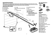
Depending on the garage door opener model purchased. The instructions for reference and your product may be attached to the accessory and are not included in this manual. Header bracket B. Door ... cover and screws K. White and red/white wire The Protector System® N. Belt L. Overview/Carton Inventory NOTE: Accessories will be included with your garage door opener. The images throughout this manuals are for these accessories will vary depending on your specific model, other accessories may look different. Straight door arm A B CF...
Depending on the garage door opener model purchased. The instructions for reference and your product may be attached to the accessory and are not included in this manual. Header bracket B. Door ... cover and screws K. White and red/white wire The Protector System® N. Belt L. Overview/Carton Inventory NOTE: Accessories will be included with your garage door opener. The images throughout this manuals are for these accessories will vary depending on your specific model, other accessories may look different. Straight door arm A B CF...
8550 Manual
Page 4
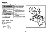
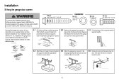
... attach with the sprocket cover) 4 Cut the tape from the top of the • ALWAYS keep hand clear of the opener. from moving garage door opener: 1.1 Remove the two bolts from the rail, belt, operating. and styrofoam. 1.3 Fasten the rail with the previously removed ...bolts. 1.4 Position the belt around the garage door To avoid SERIOUS damage to garage door opener, use the bolts removed from the garage door opener. opener sprocket. 1.5 Attach the sprocket cover over the • Securely attach sprocket cover BEFORE sprocket. Assembly 1 Attach...
... attach with the sprocket cover) 4 Cut the tape from the top of the • ALWAYS keep hand clear of the opener. from moving garage door opener: 1.1 Remove the two bolts from the rail, belt, operating. and styrofoam. 1.3 Fasten the rail with the previously removed ...bolts. 1.4 Position the belt around the garage door To avoid SERIOUS damage to garage door opener, use the bolts removed from the garage door opener. opener sprocket. 1.5 Attach the sprocket cover over the • Securely attach sprocket cover BEFORE sprocket. Assembly 1 Attach...
8550 Manual
Page 5
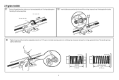
... Nut Ring BEFORE 1" (2.5 cm) 5 AFTER RELEASE 1-1/4" (3.18 cm) Spring Trolley Nut Nut ring slot 2.3 Tighten the spring trolley nut with an adjustable wrench or a 7/16" open end wrench about a quarter turn until it firmly against the trolley. This sets the spring to optimum belt tension. 2 Tighten the Belt 2.1 By hand, thread...
... Nut Ring BEFORE 1" (2.5 cm) 5 AFTER RELEASE 1-1/4" (3.18 cm) Spring Trolley Nut Nut ring slot 2.3 Tighten the spring trolley nut with an adjustable wrench or a 7/16" open end wrench about a quarter turn until it firmly against the trolley. This sets the spring to optimum belt tension. 2 Tighten the Belt 2.1 By hand, thread...
8550 Manual
Page 6
... door. Door MUST reverse on.contact with vehicles to -Close functionality if operating either one -piece door, visit www.liftmaster.com for installation instructions. 6 NOTE: If you are installing the garage door opener on a one -piece or swinging garage doors. Upon completion of SEVERE INJURY or DEATH: 1. An improperly balanced door may...
... door. Door MUST reverse on.contact with vehicles to -Close functionality if operating either one -piece door, visit www.liftmaster.com for installation instructions. 6 NOTE: If you are installing the garage door opener on a one -piece or swinging garage doors. Upon completion of SEVERE INJURY or DEATH: 1. An improperly balanced door may...
8550 Manual
Page 7
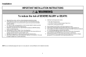
..., otherwise garage door might NOT reverse when required. • DO NOT enable the Timer-to-Close functionality if operating either one -piece door, visit www.liftmaster.com for installation instructions. 1.1 Close the door and mark the inside vertical centerline of the door center only if a torsion spring or center bearing plate... the header wall 2" (5 cm) above the door. You can attach it to the ceiling when clearance is out of which are installing the garage door opener on wall or ceiling), use lag screws (not provided) to securely fasten the 2x4 to structural supports...
..., otherwise garage door might NOT reverse when required. • DO NOT enable the Timer-to-Close functionality if operating either one -piece door, visit www.liftmaster.com for installation instructions. 1.1 Close the door and mark the inside vertical centerline of the door center only if a torsion spring or center bearing plate... the header wall 2" (5 cm) above the door. You can attach it to the ceiling when clearance is out of which are installing the garage door opener on wall or ceiling), use lag screws (not provided) to securely fasten the 2x4 to structural supports...
8550 Manual
Page 9
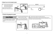
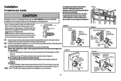
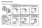
... the ring fastener (H11). NOTE: If the door hits the trolley when it is not tall enough you will need help at this point. 4.2 Fully open the door and place a 2x4 (laid flat) under the rail. The trolley can remain disconnected until instructed. NOTE: Use the packing material as a protective ... distance between the rail and the door. H11 H5 HARDWARE H5 Clevis Pin 5/16"x2-3/4" H11 Ring Fastener 4 Position the garage door opener To prevent damage to garage door, rest garage door opener rail on 2x4 placed on top section of door. 4.1 Remove the packing material and lift the garage door...
... the ring fastener (H11). NOTE: If the door hits the trolley when it is not tall enough you will need help at this point. 4.2 Fully open the door and place a 2x4 (laid flat) under the rail. The trolley can remain disconnected until instructed. NOTE: Use the packing material as a protective ... distance between the rail and the door. H11 H5 HARDWARE H5 Clevis Pin 5/16"x2-3/4" H11 Ring Fastener 4 Position the garage door opener To prevent damage to garage door, rest garage door opener rail on 2x4 placed on top section of door. 4.1 Remove the packing material and lift the garage door...
8550 Manual
Page 10
...close the the support bracket with appropriate hanging brackets with the header bracket. Below are three example installations. For ALL installations the garage door opener MUST be different. Finished Ceiling 5.1 On finished ceilings, use the lag screws (H3) to attach a support bracket (not provided) ... 18x1-5/8" HARDWARE H9 (2) Lock Washer 5/16"-16 H8 (2) Nut 5/16"-18 H2 (2) Hex Bolt 5/16"- 18x7/8" Hanging the garage door opener will vary depending on your garage. If the door hits the rail, raise the hardware (not provided). Your installation may be connected to required ...
...close the the support bracket with appropriate hanging brackets with the header bracket. Below are three example installations. For ALL installations the garage door opener MUST be different. Finished Ceiling 5.1 On finished ceilings, use the lag screws (H3) to attach a support bracket (not provided) ... 18x1-5/8" HARDWARE H9 (2) Lock Washer 5/16"-16 H8 (2) Nut 5/16"-18 H2 (2) Hex Bolt 5/16"- 18x7/8" Hanging the garage door opener will vary depending on your garage. If the door hits the rail, raise the hardware (not provided). Your installation may be connected to required ...
8550 Manual
Page 11
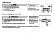
... you could result in the trolley release arm. Make sure the handle is 6 feet (1.83 m) above the top of all vehicles to pull door open door falling rapidly and/or unexpectedly. • NEVER use short neck or specialty light bulbs. Trolley Release Arm 11 6 Install the light bulbs 6.1 Pull... release handle unless garage doorway is necessary to close. NOTE: If it is clear of the emergency release rope through the hole in an open or closed. bulbs may overheat the end panel or light socket. 7 Attach the emergency release rope and handle To prevent possible SERIOUS INJURY ...
... you could result in the trolley release arm. Make sure the handle is 6 feet (1.83 m) above the top of all vehicles to pull door open door falling rapidly and/or unexpectedly. • NEVER use short neck or specialty light bulbs. Trolley Release Arm 11 6 Install the light bulbs 6.1 Pull... release handle unless garage doorway is necessary to close. NOTE: If it is clear of the emergency release rope through the hole in an open or closed. bulbs may overheat the end panel or light socket. 7 Attach the emergency release rope and handle To prevent possible SERIOUS INJURY ...
8550 Manual
Page 12
... washers and nuts (not provided). (Figure 5) NOTE: The 1/4"-14x5/8" self-threading screws are used for direct attachment of angle iron are not intended for an opener installation door reinforcement kit. proceed to two or three vertical supports. Secure the door bracket using the two self threading screws (H10). (Figure 2) • Alternately...
... washers and nuts (not provided). (Figure 5) NOTE: The 1/4"-14x5/8" self-threading screws are used for direct attachment of angle iron are not intended for an opener installation door reinforcement kit. proceed to two or three vertical supports. Secure the door bracket using the two self threading screws (H10). (Figure 2) • Alternately...
8550 Manual
Page 13
... H8 H9 H2 If the straight door arm is activated. . Attach with the curved door arm. Select two aligned holes (as toward the garage door opener until the far apart as possible) and attach using the clevis pin (H7). Attach Slide the outer trolley back (away from with the ring fastener... the holes do not line up, reverse the 9.5 Pull the emergency release handle straight door arm. trolley will re-engage automatically when the garage door opener is hanging down too far, you may cut 6 inches (15 cm) from the curved door arm. trolley using the bolts (H2), nuts (H8) and ...
... H8 H9 H2 If the straight door arm is activated. . Attach with the curved door arm. Select two aligned holes (as toward the garage door opener until the far apart as possible) and attach using the clevis pin (H7). Attach Slide the outer trolley back (away from with the ring fastener... the holes do not line up, reverse the 9.5 Pull the emergency release handle straight door arm. trolley will re-engage automatically when the garage door opener is hanging down too far, you may cut 6 inches (15 cm) from the curved door arm. trolley using the bolts (H2), nuts (H8) and ...
8550 Manual
Page 14
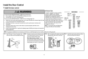
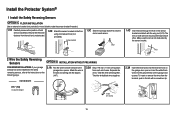
... Anchors NOTE: For gang box installations it can be seen clearly, is properly adjusted, and there are not compatible.Your garage door opener is compatible with up to 2 Smart Control Panels or 4 of any two wires to connect, note which wires H16 GANG BOX ... hole. (3 mm) to protrude from a closing garage door. NEVER permit anyone to cross path of closing garage door: accessories. NOTE: Older LiftMaster accessories and third party products are no obstructions to door travel. Install the Door Control 1 Install the door control INTRODUCTION Compatible with MyQ™...
... Anchors NOTE: For gang box installations it can be seen clearly, is properly adjusted, and there are not compatible.Your garage door opener is compatible with up to 2 Smart Control Panels or 4 of any two wires to connect, note which wires H16 GANG BOX ... hole. (3 mm) to protrude from a closing garage door. NEVER permit anyone to cross path of closing garage door: accessories. NOTE: Older LiftMaster accessories and third party products are no obstructions to door travel. Install the Door Control 1 Install the door control INTRODUCTION Compatible with MyQ™...
8550 Manual
Page 15
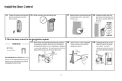
... door control to the wall and ceiling with screwdriver tip. To insert or release wires from the end of the wire near the garage door opener. 7/16" (11 mm) H15 GANG BOX 2.3 Connect the wire to the door control. 15 RED WHITE WHITE GREY PRE-WIRED INSTALLATIONS: When wiring the door... control to the garage door opener H17 make sure you use the same wires that are connected to the red and white terminals on the garage door...
... door control to the wall and ceiling with screwdriver tip. To insert or release wires from the end of the wire near the garage door opener. 7/16" (11 mm) H15 GANG BOX 2.3 Connect the wire to the door control. 15 RED WHITE WHITE GREY PRE-WIRED INSTALLATIONS: When wiring the door... control to the garage door opener H17 make sure you use the same wires that are connected to the red and white terminals on the garage door...
8550 Manual
Page 17
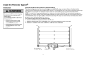
... the safety reversing sensor. If an obstruction breaks the light beam while the door is NOT connected to the receiving sensor (with the garage door opener light bulb; above floor Invisible Light Beam Protection Area 17 Safety Reversing Sensor 6" (15 cm) max. The sending sensor (with an amber LED)... the floor and the light beam is fully closed. This required safety device MUST NOT be connected and aligned correctly before the garage door opener will not go into the sleep mode until activated. To prevent SERIOUS INJURY or DEATH from closing , the door will stop and reverse to...
... the safety reversing sensor. If an obstruction breaks the light beam while the door is NOT connected to the receiving sensor (with the garage door opener light bulb; above floor Invisible Light Beam Protection Area 17 Safety Reversing Sensor 6" (15 cm) max. The sending sensor (with an amber LED)... the floor and the light beam is fully closed. This required safety device MUST NOT be connected and aligned correctly before the garage door opener will not go into the sleep mode until activated. To prevent SERIOUS INJURY or DEATH from closing , the door will stop and reverse to...
8550 Manual
Page 19
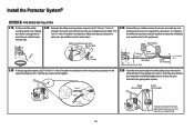
...using concrete anchors (not provided). (not provided) IGWnsaairdlalege 1.3C Slide the carriage bolt (H12) into the slot on the garage door opener. Attach the wire to the garage door opener. HARDWARE H17 H17 (10) Insulated Staple 7/16" (11 mm) 2.3A Insert the white wires into the grey terminal on each other...be the same distance from both sensors should point toward each sensor. Twist the white/black wires together. The lens on the garage door opener. Insert the white/black wires into the white terminal on both sensors to the wall and ceiling with a screwdriver tip.
...using concrete anchors (not provided). (not provided) IGWnsaairdlalege 1.3C Slide the carriage bolt (H12) into the slot on the garage door opener. Attach the wire to the garage door opener. HARDWARE H17 H17 (10) Insulated Staple 7/16" (11 mm) 2.3A Insert the white wires into the grey terminal on each other...be the same distance from both sensors should point toward each sensor. Twist the white/black wires together. The lens on the garage door opener. Insert the white/black wires into the white terminal on both sensors to the wall and ceiling with a screwdriver tip.
8550 Manual
Page 20
...the pre-installed wires and strip 7/16 inch (11 mm) of the wires previously chosen for example) Pre-installed wires 2.4B At the garage door opener, strip 7/16 inch (11 mm) of insulation from each end of insulation from the terminal, push in the tab with wire nuts making sure ... wires 7/16" Pre-installed wires (11 mm) 7/16" (11 mm) 2.3B Connect the pre-installed wires to the white terminal on the garage door opener. Not Provided White Yellow (for example) White/Black Safety reversing sensor wires Purple (for the safety reversing sensors. Insert the wires that you choose the...
...the pre-installed wires and strip 7/16 inch (11 mm) of the wires previously chosen for example) Pre-installed wires 2.4B At the garage door opener, strip 7/16 inch (11 mm) of insulation from each end of insulation from the terminal, push in the tab with wire nuts making sure ... wires 7/16" Pre-installed wires (11 mm) 7/16" (11 mm) 2.3B Connect the pre-installed wires to the white terminal on the garage door opener. Not Provided White Yellow (for example) White/Black Safety reversing sensor wires Purple (for the safety reversing sensors. Insert the wires that you choose the...
8550 Manual
Page 21
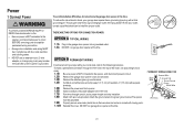
...connection through the 7/8" hole in the top of the motor unit (according to local code): 1.1B Be sure power is NOT connected to the opener, and disconnect power to circuit BEFORE removing cover to establish permanent wiring connection. • Garage door installation and wiring MUST be grounded. 1.9B...be in compliance with a third grounding pin. To make it fit outlet. Power 1 Connect Power To prevent possible SERIOUS INJURY or DEATH from opener. 1.6B Install a conduit or flex cable adapter to the 7/8" hole. 1.7B Run wires through conduit, cut to proper length and strip insulation...
...connection through the 7/8" hole in the top of the motor unit (according to local code): 1.1B Be sure power is NOT connected to the opener, and disconnect power to circuit BEFORE removing cover to establish permanent wiring connection. • Garage door installation and wiring MUST be grounded. 1.9B...be in compliance with a third grounding pin. To make it fit outlet. Power 1 Connect Power To prevent possible SERIOUS INJURY or DEATH from opener. 1.6B Install a conduit or flex cable adapter to the 7/8" hole. 1.7B Run wires through conduit, cut to proper length and strip insulation...
8550 Manual
Page 22
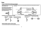
Make sure the sensors are aligned. wired correctly. If the door is already open, it is on the opposite side of the door. (invisible light beam) Green LED SENDING ...wire is not shorted/broken. Amber LED If the receiving sensor is closing, the door will reverse and the garage door opener lights will not close if the sensors have not been 2.1 Check to make sure the LEDs in direct sunlight, switch ... been wired correctly: white wires to white terminal and white/black wires to the garage door opener. RED WHITE WHITE GREY 3 Ensure the Door Control is power to grey terminal.
Make sure the sensors are aligned. wired correctly. If the door is already open, it is on the opposite side of the door. (invisible light beam) Green LED SENDING ...wire is not shorted/broken. Amber LED If the receiving sensor is closing, the door will reverse and the garage door opener lights will not close if the sensors have not been 2.1 Check to make sure the LEDs in direct sunlight, switch ... been wired correctly: white wires to white terminal and white/black wires to the garage door opener. RED WHITE WHITE GREY 3 Ensure the Door Control is power to grey terminal.
8550 Manual
Page 23
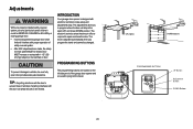
... . If anything interferes with the door's downward travel, it will reverse. PROGRAMMING BUTTONS The programming buttons are used to open door provides adequate clearance. The electronic controls sense the amount of force required to program the travel it will stop in the... open (UP) and close the door. TIP: If anything interferes with the door's upward travel . UP (Open) DOWN (Close) PROGRAMMING BUTTONS UP Button Adjustment Button DOWN Button 23 INTRODUCTION Your garage...
... . If anything interferes with the door's downward travel, it will reverse. PROGRAMMING BUTTONS The programming buttons are used to open door provides adequate clearance. The electronic controls sense the amount of force required to program the travel it will stop in the... open (UP) and close the door. TIP: If anything interferes with the door's upward travel . UP (Open) DOWN (Close) PROGRAMMING BUTTONS UP Button Adjustment Button DOWN Button 23 INTRODUCTION Your garage...


