
3265M Manual
Page 1
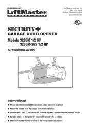
The Chamberlain Group, Inc. 845 Larch Avenue Elmhurst, Illinois 60126-1196 www.liftmaster.com ® GARAGE DOOR OPENER Models 3265M 1/2 HP 3265M-267 1/2 HP For Residential Use Only Owner's Manual ■ Please read this manual and the enclosed safety materials carefully! ■ Fasten the manual near the garage door after installation. ■ The door WILL NOT CLOSE unless the Protector System® is connected and properly aligned. ■ Periodic checks of the opener are required to ensure safe operation. ■ The model number label is located on the front panel of your opener.
The Chamberlain Group, Inc. 845 Larch Avenue Elmhurst, Illinois 60126-1196 www.liftmaster.com ® GARAGE DOOR OPENER Models 3265M 1/2 HP 3265M-267 1/2 HP For Residential Use Only Owner's Manual ■ Please read this manual and the enclosed safety materials carefully! ■ Fasten the manual near the garage door after installation. ■ The door WILL NOT CLOSE unless the Protector System® is connected and properly aligned. ■ Periodic checks of the opener are required to ensure safe operation. ■ The model number label is located on the front panel of your opener.
3265M Manual
Page 2
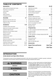
...parts 34 Accessories 35 Repair Parts and Service Back Page Warranty Back Page INTRODUCTION Safety Symbol and Signal Word Review This garage door opener has been designed and tested to offer safe service provided it is installed, operated, maintained and tested in strict accordance with the... 7 Determine the header bracket location 8 Install the header bracket 9 Attach the rail to the header bracket 10 Position the opener 10 Hang the opener 11 Install the door control 12 Install the light 13 Attach the emergency release rope and handle 13 Electrical requirements 14 Install the...
...parts 34 Accessories 35 Repair Parts and Service Back Page Warranty Back Page INTRODUCTION Safety Symbol and Signal Word Review This garage door opener has been designed and tested to offer safe service provided it is installed, operated, maintained and tested in strict accordance with the... 7 Determine the header bracket location 8 Install the header bracket 9 Attach the rail to the header bracket 10 Position the opener 10 Hang the opener 11 Install the door control 12 Install the light 13 Attach the emergency release rope and handle 13 Electrical requirements 14 Install the...
3265M Manual
Page 3
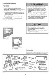
...of which are under EXTREME tension. • Disable ALL locks and remove ALL ropes connected to garage door BEFORE installing and operating garage door opener to avoid malfunction and damage. Carpenter's Level (optional) 12 Tape Measure Pencil Stepladder Drill 3/16", 5/16" Wire Cutters and 5/32" ...possible SERIOUS INJURY or DEATH: • ALWAYS call a trained door systems technician if garage door binds, sticks or is out of the opener, instructions will call a trained door systems technician. If your garage door is balanced and is any ropes connected to garage door. &#...
...of which are under EXTREME tension. • Disable ALL locks and remove ALL ropes connected to garage door BEFORE installing and operating garage door opener to avoid malfunction and damage. Carpenter's Level (optional) 12 Tape Measure Pencil Stepladder Drill 3/16", 5/16" Wire Cutters and 5/32" ...possible SERIOUS INJURY or DEATH: • ALWAYS call a trained door systems technician if garage door binds, sticks or is out of the opener, instructions will call a trained door systems technician. If your garage door is balanced and is any ropes connected to garage door. &#...

3265M Manual
Page 4
... Wall FINISHED CEILING Support bracket & fastening hardware is needed for details. Motor Unit Vertical Centerline of your garage door. Survey your garage area to your opener. See page 11. See page 11. Planning Identify the type and height of Garage Door Extension Spring OR Torsion Spring Wall-mounted Door Control Access...
... Wall FINISHED CEILING Support bracket & fastening hardware is needed for details. Motor Unit Vertical Centerline of your garage door. Survey your garage area to your opener. See page 11. See page 11. Planning Identify the type and height of Garage Door Extension Spring OR Torsion Spring Wall-mounted Door Control Access...
3265M Manual
Page 5
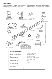
... cartons which contain the motor unit and all parts illustrated below . If anything is missing, carefully check the packing material. Carton Inventory Your garage door opener is packaged in the foam. Accessories will depend on the model purchased.
... cartons which contain the motor unit and all parts illustrated below . If anything is missing, carefully check the packing material. Carton Inventory Your garage door opener is packaged in the foam. Accessories will depend on the model purchased.
3265M Manual
Page 6
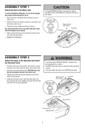
..., loosen the outer nut on the mounting plate. CAUTION: Use only the bolt previously removed from moving garage door opener: • ALWAYS keep hand clear of sprocket while operating opener. • Securely attach sprocket cover BEFORE operating. Washered Bolt 5/16"-18x12" USE ONLY THIS TYPE AND SIZE BOLT...Position chain over sprocket. ASSEMBLY STEP 1 Attach the Rail to the Motor Unit To avoid installation difficulties, do not run the garage door opener until instructed to do so. • Remove the two washered bolts mounted in top of motor unit. • Position rail at a 45&#...
..., loosen the outer nut on the mounting plate. CAUTION: Use only the bolt previously removed from moving garage door opener: • ALWAYS keep hand clear of sprocket while operating opener. • Securely attach sprocket cover BEFORE operating. Washered Bolt 5/16"-18x12" USE ONLY THIS TYPE AND SIZE BOLT...Position chain over sprocket. ASSEMBLY STEP 1 Attach the Rail to the Motor Unit To avoid installation difficulties, do not run the garage door opener until instructed to do so. • Remove the two washered bolts mounted in top of motor unit. • Position rail at a 45&#...
3265M Manual
Page 7
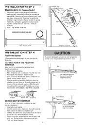
... system. ALL repairs to avoid entanglement. 5. Mount emergency release handle 6 feet (1.8 m) above floor. 6. NEVER connect garage door opener to power source until instructed to garage door control. 11. Place manual release/safety reverse test label in plain view on wall next to do...; away from the trolley. • To tighten the chain, turn outer nut in the direction shown (Figure 1). • When the chain is open, do so. 8. An improperly balanced door may notice loosening of chain after Base of Rail Adjustment Step 3 (Test the Safety Reversal System). Install ...
... system. ALL repairs to avoid entanglement. 5. Mount emergency release handle 6 feet (1.8 m) above floor. 6. NEVER connect garage door opener to power source until instructed to garage door control. 11. Place manual release/safety reverse test label in plain view on wall next to do...; away from the trolley. • To tighten the chain, turn outer nut in the direction shown (Figure 1). • When the chain is open, do so. 8. An improperly balanced door may notice loosening of chain after Base of Rail Adjustment Step 3 (Test the Safety Reversal System). Install ...

3265M Manual
Page 8
... fasten the header bracket within 4 feet (1.22 m) of the left or right of Travel Pivot One-piece door without track: One-piece door without track. Open your door to the highest point of travel clearance for the top edge of balance. Header Wall 2" (5 cm) Track Highest Point of Travel Door Door...
... fasten the header bracket within 4 feet (1.22 m) of the left or right of Travel Pivot One-piece door without track: One-piece door without track. Open your door to the highest point of travel clearance for the top edge of balance. Header Wall 2" (5 cm) Track Highest Point of Travel Door Door...
3265M Manual
Page 10
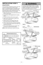
...Fastener Clevis Pin 5/16"x2-3/4" Rail Chain Pulley Bracket Rail Garage Door Clevis Pin 5/16"x2-3/4" Temporary Support INSTALLATION STEP 4 Position the Opener Follow instructions which apply to your door type as shown. • Insert a ring fastener to secure. ENGAGED Trolley Release Arm RELEASED ... the door, pull down on a temporary support to allow the rail to -rail distance. • Remove foam packaging. • Raise the opener onto a stepladder. Use packing material as a protective base. NOTE: If the door spring is convenient for setting an ideal door-to-rail distance...
...Fastener Clevis Pin 5/16"x2-3/4" Rail Chain Pulley Bracket Rail Garage Door Clevis Pin 5/16"x2-3/4" Temporary Support INSTALLATION STEP 4 Position the Opener Follow instructions which apply to your door type as shown. • Insert a ring fastener to secure. ENGAGED Trolley Release Arm RELEASED ... the door, pull down on a temporary support to allow the rail to -rail distance. • Remove foam packaging. • Raise the opener onto a stepladder. Use packing material as a protective base. NOTE: If the door spring is convenient for setting an ideal door-to-rail distance...
3265M Manual
Page 11
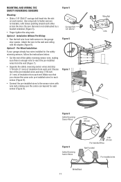
...Bolt 5/16"-18x7/8" Lock Washer 5/16" Nut 5/16"-18 11 On finished ceilings (Figure 2 and Figure 3), attach a sturdy metal bracket to opener at this time. Concrete anchors MUST be angled (Figure 1) to make sure the rail is centered over the door (or in the structural supports. 4. ...Measure Distance Bolt 5/16"-18x7/8" Lock Washer 5/16" Nut 5/16"-18 Lag Screws 5/16"-18x1-7/8" 5. Measure the distance from a falling garage door opener, fasten it securely to structural supports of the motor unit to required lengths. 3. Remove the 2x4. Attach one end of the hanging bracket to the...
...Bolt 5/16"-18x7/8" Lock Washer 5/16" Nut 5/16"-18 11 On finished ceilings (Figure 2 and Figure 3), attach a sturdy metal bracket to opener at this time. Concrete anchors MUST be angled (Figure 1) to make sure the rail is centered over the door (or in the structural supports. 4. ...Measure Distance Bolt 5/16"-18x7/8" Lock Washer 5/16" Nut 5/16"-18 Lag Screws 5/16"-18x1-7/8" 5. Measure the distance from a falling garage door opener, fasten it securely to structural supports of the motor unit to required lengths. 3. Remove the 2x4. Attach one end of the hanging bracket to the...
3265M Manual
Page 12
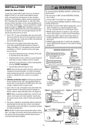
... a small flat head screwdriver (Figure 4). Adjust screw for snug fit. • Install top screw with a staple, creating a short or open position but will not return to motor unit. DO NOT overtighten. • Insert bottom tabs and snap on a smooth surface. If a click is not...to the quick-connect terminals as in sight until the sensor beam is NOT connected BEFORE installing door control. • Connect ONLY to the opener, twist same color wires together. Insert wires into drywall (Figure 1), drill 5/32" holes and use anchors provided. HARDWARE SHOWN ACTUAL SIZE ...
... a small flat head screwdriver (Figure 4). Adjust screw for snug fit. • Install top screw with a staple, creating a short or open position but will not return to motor unit. DO NOT overtighten. • Insert bottom tabs and snap on a smooth surface. If a click is not...to the quick-connect terminals as in sight until the sensor beam is NOT connected BEFORE installing door control. • Connect ONLY to the opener, twist same color wires together. Insert wires into drywall (Figure 1), drill 5/32" holes and use anchors provided. HARDWARE SHOWN ACTUAL SIZE ...
3265M Manual
Page 13
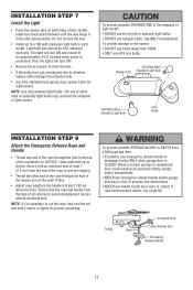
...Lens Hinge INSTALLATION STEP 8 Attach the Emergency Release Rope and Handle • Thread one end of the rope through the hole in an open or closed. Trolley Overhand Knot Rope NOTICE Trolley Release Arm Emergency Release Handle 13 To prevent possible OVERHEATING of the outer trolley. •... in each socket. Ensure that the rope and handle clear the tops of persons and obstructions. • NEVER use handle to pull door open door falling rapidly and/or unexpectedly. • NEVER use emergency release handle to avoid entanglement. Then the lights will turn OFF. •...
...Lens Hinge INSTALLATION STEP 8 Attach the Emergency Release Rope and Handle • Thread one end of the rope through the hole in an open or closed. Trolley Overhand Knot Rope NOTICE Trolley Release Arm Emergency Release Handle 13 To prevent possible OVERHEATING of the outer trolley. •... in each socket. Ensure that the rope and handle clear the tops of persons and obstructions. • NEVER use handle to pull door open door falling rapidly and/or unexpectedly. • NEVER use emergency release handle to avoid entanglement. Then the lights will turn OFF. •...
3265M Manual
Page 14
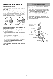
... type outlet. To prevent possible SERIOUS INJURY or DEATH from electrocution or fire: • Be sure power is NOT connected to the opener, and disconnect power to circuit BEFORE removing cover to establish permanent wiring connection. • Garage door installation and wiring MUST be grounded. •...; Reinstall the cover. Black • Remove the attached 3-prong cord. The opener must be in compliance with a third grounding pin. To reduce the risk of the motor unit: • Remove the motor unit cover screws ...
... type outlet. To prevent possible SERIOUS INJURY or DEATH from electrocution or fire: • Be sure power is NOT connected to the opener, and disconnect power to circuit BEFORE removing cover to establish permanent wiring connection. • Garage door installation and wiring MUST be grounded. •...; Reinstall the cover. Black • Remove the attached 3-prong cord. The opener must be in compliance with a third grounding pin. To reduce the risk of the motor unit: • Remove the motor unit cover screws ...

3265M Manual
Page 15
...to the receiving eye (with a green indicator light). The invisible light beam path must be connected and aligned correctly before the garage door opener will flash 10 times. The sending eye (with an amber indicator light) transmits an invisible light beam to the garage door... garage door: • Correctly connect and align the safety reversing sensor. This required safety device MUST NOT be securely fastened to full open position, and the opener lights will move in the down direction. above garage floor. If an obstruction breaks the light beam while the door is NO...
...to the receiving eye (with a green indicator light). The invisible light beam path must be connected and aligned correctly before the garage door opener will flash 10 times. The sending eye (with an amber indicator light) transmits an invisible light beam to the garage door... garage door: • Correctly connect and align the safety reversing sensor. This required safety device MUST NOT be securely fastened to full open position, and the opener lights will move in the down direction. above garage floor. If an obstruction breaks the light beam while the door is NO...
3265M Manual
Page 16
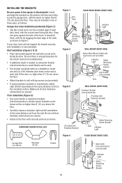
... (RIGHT SIDE) Carriage Bolt 1/4"-20x1/2" Wing Nut 1/4"-20 Staples 16 Attach with curved arms facing the door. INSTALLING THE BRACKETS Be sure power to the opener is recommended. Make sure all door hardware obstructions are cleared. They may be installed in Figure 1. HARDWARE SHOWN ACTUAL SIZE Figure 1 Door Track Lip DOOR...
... (RIGHT SIDE) Carriage Bolt 1/4"-20x1/2" Wing Nut 1/4"-20 Staples 16 Attach with curved arms facing the door. INSTALLING THE BRACKETS Be sure power to the opener is recommended. Make sure all door hardware obstructions are cleared. They may be installed in Figure 1. HARDWARE SHOWN ACTUAL SIZE Figure 1 Door Track Lip DOOR...
3265M Manual
Page 17
... the wall (Figure 7). • Separate the safety reversing sensor wires and strip 7/16 inch (11 mm) of insulation from both sensors to the garage door opener. Be sure the lens is enough wire to brackets, with lenses pointing toward each other across the door. Option A - Option B - Make sure that you choose...
... the wall (Figure 7). • Separate the safety reversing sensor wires and strip 7/16 inch (11 mm) of insulation from both sensors to the garage door opener. Be sure the lens is enough wire to brackets, with lenses pointing toward each other across the door. Option A - Option B - Make sure that you choose...

3265M Manual
Page 18
... and white/black wires sufficiently to connect to Quick-Connect Terminals Bell Wire 1. Figure 10 Bell Wire Finished Ceiling Connect Wire to the opener quick-connect terminals. Strip wire 7/16" (11 mm) 7/16" (11 mm) 2. If the sending eye indicator light glows steadily but the receiving.... • Loosen the receiving eye wing nut and adjust sensor until it will glow steadily if wiring connections and alignment are correct. The opener lights will reverse. When the green indicator light glows steadily, tighten the wing nut. The indicator lights in the receiving eye is off, dim...
... and white/black wires sufficiently to connect to Quick-Connect Terminals Bell Wire 1. Figure 10 Bell Wire Finished Ceiling Connect Wire to the opener quick-connect terminals. Strip wire 7/16" (11 mm) 7/16" (11 mm) 2. If the sending eye indicator light glows steadily but the receiving.... • Loosen the receiving eye wing nut and adjust sensor until it will glow steadily if wiring connections and alignment are correct. The opener lights will reverse. When the green indicator light glows steadily, tighten the wing nut. The indicator lights in the receiving eye is off, dim...

3265M Manual
Page 19
... Edge of Door or Reinforcement Board Vertical Centerline of Garage Door UP Vertical Centerline of door bracket. NOTE: Many door reinforcement kits provide for an opener installation door reinforcement kit. Position the top edge of the bracket 2"-4" (5-10 cm) below the top edge of the door, OR directly below or on...
... Edge of Door or Reinforcement Board Vertical Centerline of Garage Door UP Vertical Centerline of door bracket. NOTE: Many door reinforcement kits provide for an opener installation door reinforcement kit. Position the top edge of the bracket 2"-4" (5-10 cm) below the top edge of the door, OR directly below or on...

3265M Manual
Page 21
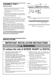
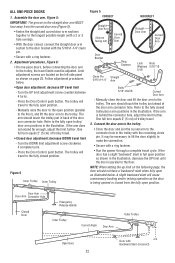
... the solid end. Secure the connection with the 5/16"x1" clevis pin. Figure 2: • Bring arm sections together. Trolley will re-engage automatically when opener is fully closed. Figure 3, Hole alignment alternative: • If holes in curved arm are above holes in the same way, using the 5/16"x1-1/4" clevis... far apart as possible to increase door arm rigidity. SECTIONAL DOORS ONLY Make sure garage door is operated. Pull the emergency release handle toward the opener at a 45° angle so that line up and join with cut end down as shown in Figures 1, 2 and 3. Find two pairs of...
... the solid end. Secure the connection with the 5/16"x1" clevis pin. Figure 2: • Bring arm sections together. Trolley will re-engage automatically when opener is fully closed. Figure 3, Hole alignment alternative: • If holes in curved arm are above holes in the same way, using the 5/16"x1-1/4" clevis... far apart as possible to increase door arm rigidity. SECTIONAL DOORS ONLY Make sure garage door is operated. Pull the emergency release handle toward the opener at a 45° angle so that line up and join with cut end down as shown in Figures 1, 2 and 3. Find two pairs of...
3265M Manual
Page 22
...slant will travel limit - Door Arm Door Arm Connector Hole Closed Door Emergency Release Handle Inner Trolley Correct Angle Door Arm Outer Trolley Open Door 22 Door with the remaining clevis pin. The arm should touch the trolley just in the trolley with Backward Slant (Incorrect)...the illustration. Refer to the door bracket with the 5/16"x1-1/4" clevis pin. • Secure with a ring fastener. • Run the opener through a complete travel limit - Turn the DOWN limit adjustment screw clockwise 4 complete turns. - Press the Door Control push button. The trolley will...
...slant will travel limit - Door Arm Door Arm Connector Hole Closed Door Emergency Release Handle Inner Trolley Correct Angle Door Arm Outer Trolley Open Door 22 Door with the remaining clevis pin. The arm should touch the trolley just in the trolley with Backward Slant (Incorrect)...the illustration. Refer to the door bracket with the 5/16"x1-1/4" clevis pin. • Secure with a ring fastener. • Run the opener through a complete travel limit - Turn the DOWN limit adjustment screw clockwise 4 complete turns. - Press the Door Control push button. The trolley will...


