
3265M Manual
Page 1
The Chamberlain Group, Inc. 845 Larch Avenue Elmhurst, Illinois 60126-1196 www.liftmaster.com ® GARAGE DOOR OPENER Models 3265M 1/2 HP 3265M-267 1/2 HP For Residential Use Only Owner's Manual ■ Please read this manual and the enclosed safety materials carefully! ■ Fasten the manual near the garage door after installation. ■ The door WILL NOT CLOSE unless the Protector System® is connected and properly aligned. ■ Periodic checks of the opener are required to ensure safe operation. ■ The model number label is located on the front panel of your opener.
The Chamberlain Group, Inc. 845 Larch Avenue Elmhurst, Illinois 60126-1196 www.liftmaster.com ® GARAGE DOOR OPENER Models 3265M 1/2 HP 3265M-267 1/2 HP For Residential Use Only Owner's Manual ■ Please read this manual and the enclosed safety materials carefully! ■ Fasten the manual near the garage door after installation. ■ The door WILL NOT CLOSE unless the Protector System® is connected and properly aligned. ■ Periodic checks of the opener are required to ensure safe operation. ■ The model number label is located on the front panel of your opener.
3265M Manual
Page 2
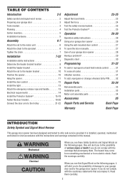
... garage door opener 28 Having a problem 29 Diagnostic chart 30 Programming 31-32 To add or reprogram a hand-held remote control 31 To erase all codes 31 3-Button remotes 31 To add, reprogram or change a Keyless Entry PIN . . . . . 32 Repair Parts 33-34 Rail assembly parts 33 Installation parts 33 Motor unit assembly parts 34 Accessories 35 Repair Parts and Service Back Page Warranty Back Page INTRODUCTION Safety Symbol and Signal Word Review This garage door opener has been designed and tested to your garage door opener 26 Using the wall-mounted door control...
... garage door opener 28 Having a problem 29 Diagnostic chart 30 Programming 31-32 To add or reprogram a hand-held remote control 31 To erase all codes 31 3-Button remotes 31 To add, reprogram or change a Keyless Entry PIN . . . . . 32 Repair Parts 33-34 Rail assembly parts 33 Installation parts 33 Motor unit assembly parts 34 Accessories 35 Repair Parts and Service Back Page Warranty Back Page INTRODUCTION Safety Symbol and Signal Word Review This garage door opener has been designed and tested to your garage door opener 26 Using the wall-mounted door control...

3265M Manual
Page 4
.... Planning Identify the type and height of your opener. Survey your installation. See page 19 for lightweight garage doors (fiberglass, steel, aluminum, door with the installation of Garage Door Extension Spring OR Torsion Spring Wall-mounted Door Control Access Door --- --- -- Motor Unit Vertical Centerline of your garage door. See page 11. Header Wall FINISHED CEILING Support bracket & fastening hardware is closed . Slack in chain tension is normal when garage door is required. Additional materials may find...
.... Planning Identify the type and height of your opener. Survey your installation. See page 19 for lightweight garage doors (fiberglass, steel, aluminum, door with the installation of Garage Door Extension Spring OR Torsion Spring Wall-mounted Door Control Access Door --- --- -- Motor Unit Vertical Centerline of your garage door. See page 11. Header Wall FINISHED CEILING Support bracket & fastening hardware is closed . Slack in chain tension is normal when garage door is required. Additional materials may find...
3265M Manual
Page 6
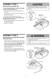
... cover slightly and insert the front tab in the top of the opener. To avoid possible SERIOUS INJURY to fingers from rail, chain and styrofoam. • REMOVE STYROFOAM. ASSEMBLY STEP 1 Attach the Rail to the Motor Unit To avoid installation difficulties, do not run the garage door opener until instructed to do so. • Remove the two washered bolts mounted in top of motor unit...
... cover slightly and insert the front tab in the top of the opener. To avoid possible SERIOUS INJURY to fingers from rail, chain and styrofoam. • REMOVE STYROFOAM. ASSEMBLY STEP 1 Attach the Rail to the Motor Unit To avoid installation difficulties, do not run the garage door opener until instructed to do so. • Remove the two washered bolts mounted in top of motor unit...
3265M Manual
Page 7
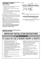
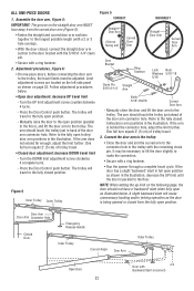
... Rail INSTALLATION IMPORTANT INSTALLATION INSTRUCTIONS WARNING To reduce the risk of installation, test safety reversal system. Install garage door opener ONLY on inside of Rail Adjustment Step 3 (Test the Safety Reversal System). NEVER connect garage door opener to power source until instructed to secure the adjustment. WARNING NOTE: During future maintenance, ALWAYS pull the emergency release handle to cables, spring assemblies and other hardware MUST be caught in SEVERE INJURY or DEATH. 3. An improperly balanced door may notice some chain Chain...
... Rail INSTALLATION IMPORTANT INSTALLATION INSTRUCTIONS WARNING To reduce the risk of installation, test safety reversal system. Install garage door opener ONLY on inside of Rail Adjustment Step 3 (Test the Safety Reversal System). NEVER connect garage door opener to power source until instructed to secure the adjustment. WARNING NOTE: During future maintenance, ALWAYS pull the emergency release handle to cables, spring assemblies and other hardware MUST be caught in SEVERE INJURY or DEATH. 3. An improperly balanced door may notice some chain Chain...
3265M Manual
Page 11
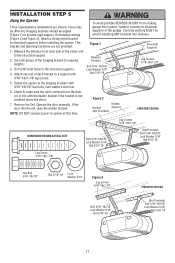
... motor unit to required lengths. 3. Operate the door manually. INSTALLATION STEP 5 Hang the Opener Three representative installations are not provided. 1. To avoid possible SERIOUS INJURY from each bracket to the hanging brackets with the header bracket if the bracket is centered over the door (or in the structural supports. 4. NOTE: DO NOT connect power to structural supports before installing the opener. If the door hits the rail, raise the header bracket. This bracket...
... motor unit to required lengths. 3. Operate the door manually. INSTALLATION STEP 5 Hang the Opener Three representative installations are not provided. 1. To avoid possible SERIOUS INJURY from each bracket to the hanging brackets with the header bracket if the bracket is centered over the door (or in the structural supports. 4. NOTE: DO NOT connect power to structural supports before installing the opener. If the door hits the rail, raise the header bracket. This bracket...
3265M Manual
Page 12
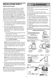
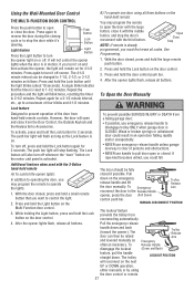
... Light features will not function (reverse wires to motor unit. Fasten with a small flat this time. If a click is properly adjusted and there are no obstructions to a single gang box (Figure 2). Strip 7/16" (11 mm) of door. • NEVER permit children to operate or play with care to the close position until the sensor beam is NOT connected BEFORE installing door control. • Connect ONLY to wall near door control, and manual release/safety reverse...
... Light features will not function (reverse wires to motor unit. Fasten with a small flat this time. If a click is properly adjusted and there are no obstructions to a single gang box (Figure 2). Strip 7/16" (11 mm) of door. • NEVER permit children to operate or play with care to the close position until the sensor beam is NOT connected BEFORE installing door control. • Connect ONLY to wall near door control, and manual release/safety reverse...
3265M Manual
Page 13
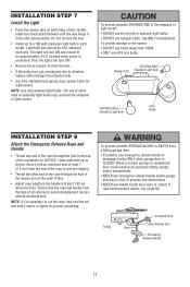
... an open door falling rapidly and/or unexpectedly. • NEVER use emergency release handle unless garage doorway is connected. Gently rotate lens back and downward until the lens hinge is CLOSED. Then the lights will turn OFF. • Reverse the procedure to close the lens. • If the bulbs burn out prematurely due to disengage trolley ONLY when garage door is in the release arm of the red handle...
... an open door falling rapidly and/or unexpectedly. • NEVER use emergency release handle unless garage doorway is connected. Gently rotate lens back and downward until the lens hinge is CLOSED. Then the lights will turn OFF. • Reverse the procedure to close the lens. • If the bulbs burn out prematurely due to disengage trolley ONLY when garage door is in the release arm of the red handle...

3265M Manual
Page 15
... the wall framing. If it is NOT connected to the receiving eye (with an amber indicator light) transmits an invisible light beam to the garage door opener BEFORE installing the safety reversing sensor. To prevent SERIOUS INJURY or DEATH from inside the garage so that the sending and receiving eyes face each location to full open position, and the opener lights will flash 10 times. Safety Reversing Sensor Invisible Light Beam 6" (15 cm) max. If installing in...
... the wall framing. If it is NOT connected to the receiving eye (with an amber indicator light) transmits an invisible light beam to the garage door opener BEFORE installing the safety reversing sensor. To prevent SERIOUS INJURY or DEATH from inside the garage so that the sending and receiving eyes face each location to full open position, and the opener lights will flash 10 times. Safety Reversing Sensor Invisible Light Beam 6" (15 cm) max. If installing in...
3265M Manual
Page 16
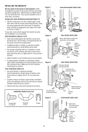
... Light Safety Reversing Sensor Bracket Lag Screws (not provided) Lens WALL MOUNT (RIGHT SIDE) Extension Bracket (See Accessories) (Provided with Extension Bracket) (Provided with Extension Bracket) Safety Reversing Sensor Bracket Lens Indicator Light Figure 4 FLOOR MOUNT (RIGHT SIDE) Carriage Bolt 1/4"-20x1/2" Wing Nut 1/4"-20 Staples 16 Attach with the curved arms facing the door. If your door track will face each door track, with Concrete Anchors (not provided) Lens Indicator Light Safety Reversing Sensor Bracket INSTALLING THE BRACKETS Be sure power to the opener...
... Light Safety Reversing Sensor Bracket Lag Screws (not provided) Lens WALL MOUNT (RIGHT SIDE) Extension Bracket (See Accessories) (Provided with Extension Bracket) (Provided with Extension Bracket) Safety Reversing Sensor Bracket Lens Indicator Light Figure 4 FLOOR MOUNT (RIGHT SIDE) Carriage Bolt 1/4"-20x1/2" Wing Nut 1/4"-20 Staples 16 Attach with the curved arms facing the door. If your door track will face each door track, with Concrete Anchors (not provided) Lens Indicator Light Safety Reversing Sensor Bracket INSTALLING THE BRACKETS Be sure power to the opener...
3265M Manual
Page 22
... the connection. • Secure with the remaining clevis pin. NOTE: When setting the up limit on the left side panel as the door is being opened or closed position. Follow adjustment procedures below . Manually raise the door to the open as shown in the illustration. Press the Door Control push button. Refer to the trolley. Door Arm Door Arm Connector Hole Closed Door Emergency Release Handle Inner Trolley Correct Angle Door Arm Outer Trolley Open Door 22 Door with a ring fastener. 2. Limit adjustment screws are located on...
... the connection. • Secure with the remaining clevis pin. NOTE: When setting the up limit on the left side panel as the door is being opened or closed position. Follow adjustment procedures below . Manually raise the door to the open as shown in the illustration. Press the Door Control push button. Refer to the trolley. Door Arm Door Arm Connector Hole Closed Door Emergency Release Handle Inner Trolley Correct Angle Door Arm Outer Trolley Open Door 22 Door with a ring fastener. 2. Limit adjustment screws are located on...

3265M Manual
Page 23
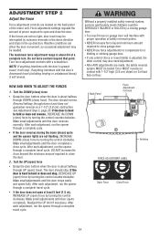
.... To operate the opener, press the Door Control push bar. Use a screwdriver to Adjustment Step 2. If anything interferes with the door's upward travel . One turn equals 2" (5 cm) of travel cycle: If the opener lights are flashing, the Safety Reversing Sensors are outlined below. Turn the down limit adjustment screw clockwise. See Troubleshooting, page 18. Adjustment procedures are either not installed, misaligned, or obstructed. Simply wait 15 minutes and try lengthening the door arm (page...
.... To operate the opener, press the Door Control push bar. Use a screwdriver to Adjustment Step 2. If anything interferes with the door's upward travel . One turn equals 2" (5 cm) of travel cycle: If the opener lights are flashing, the Safety Reversing Sensors are outlined below. Turn the down limit adjustment screw clockwise. See Troubleshooting, page 18. Adjustment procedures are either not installed, misaligned, or obstructed. Simply wait 15 minutes and try lengthening the door arm (page...
3265M Manual
Page 24
... close the door. 2. Back Panel Force Adjustment Controls KG KG Antenna FORCE ADJUSTMENT LABEL Open Force Close Force 24 Force adjustment settings regulate the amount of the motor unit. If anything interferes with the door's upward travel, it will reverse. The door should stop , DECREASE UP (open ) travel. After each adjustment, run the opener through a complete travel cycle. After each adjustment, run the opener through DOWN (close ) cycle and the opener lights are made, the safety reversal system MUST be needed. The door should reverse. If the door...
... close the door. 2. Back Panel Force Adjustment Controls KG KG Antenna FORCE ADJUSTMENT LABEL Open Force Close Force 24 Force adjustment settings regulate the amount of the motor unit. If anything interferes with the door's upward travel, it will reverse. The door should stop , DECREASE UP (open ) travel. After each adjustment, run the opener through a complete travel cycle. After each adjustment, run the opener through DOWN (close ) cycle and the opener lights are made, the safety reversal system MUST be needed. The door should reverse. If the door...
3265M Manual
Page 26
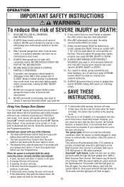
...; The wall-mounted Door Control: Hold the push button or bar down travel is initially plugged in the opening , the door will stop . However, you release them until down until the door starts to a matching code which are made by a trained door systems technician. 14. Bulb power is CLOSED. off as follows: With the opener lights off automatically after interruption; If the door has been stopped in a partially open , the door will close . OPERATION IMPORTANT SAFETY INSTRUCTIONS WARNING...
...; The wall-mounted Door Control: Hold the push button or bar down travel is initially plugged in the opening , the door will stop . However, you release them until down until the door starts to a matching code which are made by a trained door systems technician. 14. Bulb power is CLOSED. off as follows: With the opener lights off automatically after interruption; If the door has been stopped in a partially open , the door will close . OPERATION IMPORTANT SAFETY INSTRUCTIONS WARNING...
3265M Manual
Page 27
... Keyless Entry Accessories. Repeat the procedure and the light will flash as long as the Lock feature is activated. However, the door will also turn it off whenever the "learn" button on the motor unit panel is on the emergency release handle and lift the door manually. The Lock feature will open the door with the large button, close it with the middle button, and stop the door's movement with the 3-Button hand-held remote...
... Keyless Entry Accessories. Repeat the procedure and the light will flash as long as the Lock feature is activated. However, the door will also turn it off whenever the "learn" button on the motor unit panel is on the emergency release handle and lift the door manually. The Lock feature will open the door with the large button, close it with the middle button, and stop the door's movement with the 3-Button hand-held remote...
3265M Manual
Page 28
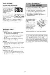
... away the existing grease from the garage door opener rail. Replace the battery with 3V2032 coin batteries. • DO NOT recharge, disassemble, heat above 100° C (212° F) or incinerate. Tested to 5 years. Adjust limits and/or force if necessary. (See pages 23 and 24.) • Repeat the safety reverse test. Two Times a Year • Check chain tension. THE REMOTE CONTROL BATTERY To prevent possible SERIOUS INJURY...
... away the existing grease from the garage door opener rail. Replace the battery with 3V2032 coin batteries. • DO NOT recharge, disassemble, heat above 100° C (212° F) or incinerate. Tested to 5 years. Adjust limits and/or force if necessary. (See pages 23 and 24.) • Repeat the safety reverse test. Two Times a Year • Check chain tension. THE REMOTE CONTROL BATTERY To prevent possible SERIOUS INJURY...
3265M Manual
Page 29
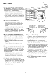
... the trolley is normal. Bell Wire Safety Reversing Sensor "Learn" Button LED or Diagnostic LED Sending Eye Safety Receiving Eye Safety Reversing Sensor Reversing Sensor (Amber Indicator Light) (Green Indicator Light) 3. The need for occasional adjustment for Using the Wall Mounted Door Control. • Reprogram remotes following the instructions for the force and limit settings is blinking, deactivate the Lock Mode following the programming instructions. If the trolley re-engages with a security light feature. My remotes will not close and the light bulbs blink on...
... the trolley is normal. Bell Wire Safety Reversing Sensor "Learn" Button LED or Diagnostic LED Sending Eye Safety Receiving Eye Safety Reversing Sensor Reversing Sensor (Amber Indicator Light) (Green Indicator Light) 3. The need for occasional adjustment for Using the Wall Mounted Door Control. • Reprogram remotes following the instructions for the force and limit settings is blinking, deactivate the Lock Mode following the programming instructions. If the trolley re-engages with a security light feature. My remotes will not close and the light bulbs blink on...
3265M Manual
Page 30
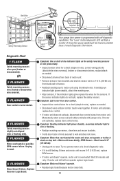
...eye to 1-2 ft. (30-60 cm) from motor unit. If motor unit activates, replace door control. • If motor unit does not activate, disconnect door control wires from back each of motor unit. • Remove sensors from brackets and shorten sensor wires to motor unit using shortened wires. RPM Sensor = Short travel 6-8" (15-20 cm). • Unplug unit to reset. 6 FLASHES Motor Circuit Failure. Bell Wire Safety Reversing Sensor Diagnostics Located On Motor Unit LED or Diagnostic LED "Learn" Button Installed Safety Reversing Sensor Your garage door opener is overheated. OR 2 FLASHES...
...eye to 1-2 ft. (30-60 cm) from motor unit. If motor unit activates, replace door control. • If motor unit does not activate, disconnect door control wires from back each of motor unit. • Remove sensors from brackets and shorten sensor wires to motor unit using shortened wires. RPM Sensor = Short travel 6-8" (15-20 cm). • Unplug unit to reset. 6 FLASHES Motor Circuit Failure. Bell Wire Safety Reversing Sensor Diagnostics Located On Motor Unit LED or Diagnostic LED "Learn" Button Installed Safety Reversing Sensor Your garage door opener is overheated. OR 2 FLASHES...
3265M Manual
Page 31
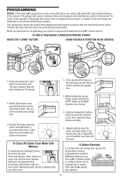
... keyless entry you wish to operate your garage door. 3. LOCK LIGHT 3. LOCK LIGHT 4. Your garage door opener has already been programmed at the factory to operate with your hand-held remote* that technical measure. It has learned the code. While holding both buttons while you press the large push button. The door will open and close when you press the push bar on motor unit until the learn " button on the door control (all codes: Press and hold the LIGHT button on the motor unit. If light bulbs...
... keyless entry you wish to operate your garage door. 3. LOCK LIGHT 3. LOCK LIGHT 4. Your garage door opener has already been programmed at the factory to operate with your hand-held remote* that technical measure. It has learned the code. While holding both buttons while you press the large push button. The door will open and close when you press the push bar on motor unit until the learn " button on the door control (all codes: Press and hold the LIGHT button on the motor unit. If light bulbs...

3265M Manual
Page 36
... PROVIDE REASONABLE AND NECESSARY MAINTENANCE, UNAUTHORIZED REPAIRS OR ANY ALTERATIONS TO THIS PRODUCT), LABOR CHARGES FOR REINSTALLING A REPAIRED OR REPLACED UNIT, REPLACEMENT OF BATTERIES AND LIGHT BULBS OR UNITS INSTALLED FOR NON-RESIDENTIAL USE. THIS LIMITED WARRANTY DOES NOT COVER ANY PROBLEMS WITH, OR RELATING TO, THE GARAGE DOOR OR GARAGE DOOR HARDWARE, INCLUDING BUT NOT LIMITED TO THE DOOR SPRINGS, DOOR ROLLERS, DOOR ALIGNMENT OR HINGES. All Rig3h6ts Reserved ANY SERVICE CALL THAT DETERMINES...
... PROVIDE REASONABLE AND NECESSARY MAINTENANCE, UNAUTHORIZED REPAIRS OR ANY ALTERATIONS TO THIS PRODUCT), LABOR CHARGES FOR REINSTALLING A REPAIRED OR REPLACED UNIT, REPLACEMENT OF BATTERIES AND LIGHT BULBS OR UNITS INSTALLED FOR NON-RESIDENTIAL USE. THIS LIMITED WARRANTY DOES NOT COVER ANY PROBLEMS WITH, OR RELATING TO, THE GARAGE DOOR OR GARAGE DOOR HARDWARE, INCLUDING BUT NOT LIMITED TO THE DOOR SPRINGS, DOOR ROLLERS, DOOR ALIGNMENT OR HINGES. All Rig3h6ts Reserved ANY SERVICE CALL THAT DETERMINES...


