3255 Manual
Page 7
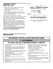
...its midpoint, re-tighten the inner nut to garage door control. 11. ASSEMBLY STEP 3 Tighten the Chain • Spin the inner nut and lock washer down the trolley threaded shaft, away from ALL moving parts of the door. 10. Base of Rail Mid Length of SEVERE INJURY...floor. 7 READ AND FOLLOW ALL INSTALLATION WARNINGS AND INSTRUCTIONS. 2. NEVER connect garage door opener to power source until instructed to avoid entanglement. 5. Disable ALL locks and remove ALL ropes connected to garage door BEFORE installing opener to do not re-adjust the chain. Trolley Figure 2 Sprocket ...
...its midpoint, re-tighten the inner nut to garage door control. 11. ASSEMBLY STEP 3 Tighten the Chain • Spin the inner nut and lock washer down the trolley threaded shaft, away from ALL moving parts of the door. 10. Base of Rail Mid Length of SEVERE INJURY...floor. 7 READ AND FOLLOW ALL INSTALLATION WARNINGS AND INSTRUCTIONS. 2. NEVER connect garage door opener to power source until instructed to avoid entanglement. 5. Disable ALL locks and remove ALL ropes connected to garage door BEFORE installing opener to do not re-adjust the chain. Trolley Figure 2 Sprocket ...
3255 Manual
Page 12
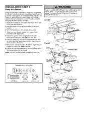
...structural support. 2. Grease the top and underside of the motor unit to the hanging brackets with rail grease. NOTE: DO NOT connect power to provide rigid support. Yours may be used if installing any brackets into masonry. Cut both pieces of the garage. Remove the 2x4... of each side of the rail surface where the trolley slides with 5/16"-18x7/8" hex bolts, lock washers and nuts. 6. Operate the door manually. Measure the distance from a falling garage door opener, fasten it SECURELY to structural supports of the hanging bracket to structural supports before installing the...
...structural support. 2. Grease the top and underside of the motor unit to the hanging brackets with rail grease. NOTE: DO NOT connect power to provide rigid support. Yours may be used if installing any brackets into masonry. Cut both pieces of the garage. Remove the 2x4... of each side of the rail surface where the trolley slides with 5/16"-18x7/8" hex bolts, lock washers and nuts. 6. Operate the door manually. Measure the distance from a falling garage door opener, fasten it SECURELY to structural supports of the hanging bracket to structural supports before installing the...
3255 Manual
Page 13
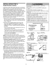
...and red/white to 24 VOLT low voltage wires. To prevent possible SERIOUS INJURY or DEATH from electrocution: • Be sure power is NOT connected BEFORE installing door control. • Connect ONLY to red. 5. HARDWARE SHOWN ACTUAL SIZE Screw 6ABx1-1/4" (std installation) Insulated Staples Screw 6-32x1... Tabs First 24 Volt Bell Wire Figure 3 MULTI-FUNCTION Figure 4 REMOVE COVER DOOR CONTROL (BACK) Top Mounting Hole Slot Terminal Screws Bell Wire Bottom Mounting Hole LOCK LIGHT Figure 5 Door Control Connections To release or insert wire, push in new home construction), it can...
...and red/white to 24 VOLT low voltage wires. To prevent possible SERIOUS INJURY or DEATH from electrocution: • Be sure power is NOT connected BEFORE installing door control. • Connect ONLY to red. 5. HARDWARE SHOWN ACTUAL SIZE Screw 6ABx1-1/4" (std installation) Insulated Staples Screw 6-32x1... Tabs First 24 Volt Bell Wire Figure 3 MULTI-FUNCTION Figure 4 REMOVE COVER DOOR CONTROL (BACK) Top Mounting Hole Slot Terminal Screws Bell Wire Bottom Mounting Hole LOCK LIGHT Figure 5 Door Control Connections To release or insert wire, push in new home construction), it can...

3255 Manual
Page 18
... but the receiving eye indicator light doesn't: • Check alignment. • Check for : • Electric power to the opener. • A short in place. • Loosen the receiving eye wing nut and adjust... steadily if wiring connections and alignment are correct. If the receiving eye indicator light is closing, the door will blink 10 times. Strip wire 7/16" (11 mm) 7/16" (11 mm) 2. Insert... 3. The indicator lights in tab with lenses pointing toward each set of alignment or obstruction. Lock in the white or white/black wires. If the sending eye indicator light does not glow ...
... but the receiving eye indicator light doesn't: • Check alignment. • Check for : • Electric power to the opener. • A short in place. • Loosen the receiving eye wing nut and adjust... steadily if wiring connections and alignment are correct. If the receiving eye indicator light is closing, the door will blink 10 times. Strip wire 7/16" (11 mm) 7/16" (11 mm) 2. Insert... 3. The indicator lights in tab with lenses pointing toward each set of alignment or obstruction. Lock in the white or white/black wires. If the sending eye indicator light does not glow ...


